简介
这是三款直流电机都自带减速器和编码器,驱动电压为6V。该电机自带霍尔型编码器,编码器的分辨率为11x减速比,D形输出轴。对于各种移动机器人项目和中型移动平台,该电机都是一个非常理想的选择。
技术规格
FIT0520
- 额定电压:6V
- 空载转速参数:300RPM 0.1A
- 最大效率点参数:负载0.7kg•cm/245RPM/1.2W/0.4A
- 最大功率点参数:负载1.8kg•cm/160RPM/2W/0.8A
- 堵转参数:3.6kg•cm 堵死电流2.7A
- 减速器减速比:1:20
- 霍尔分辨率:霍尔分辨率11x精确减速比20.4=224.4PPR/转RPM
- 产品尺寸:50 * Φ24.4 mm / 1.97 * Φ0.96inches
FIT0521
- 额定电压:6V
- 空载转速参数:210RPM 0.13A
- 最大效率点参数:负载2.0kg•cm/170RPM/2.0W/0.6A
- 最大功率点参数:负载5.2kg•cm/110RPM/3.1W/1.1A
- 堵转参数:10kg•cm 堵死电流3.2A
- 减速器减速比:1:34
- 霍尔分辨率:霍尔分辨率11x精确减速比34.02=341.2PPR
- 产品尺寸:52 * Φ24.4 mm / 2.05 * Φ0.96inches
FIT0522
- 额定电压:6V
- 空载转速参数:100RPM 0.13A
- 最大效率点参数:负载1.0kg•cm/80RPM/1.7W/0.5A
- 最大功率点参数:负载3.0kg•cm/55RPM/2.8W/1.0A
- 堵转参数:6.5kg•cm 堵死电流3.0A
- 减速器减速比:1:75
- 霍尔分辨率:霍尔分辨率11x精确减速比74.83=823.1PPR
- 产品尺寸:54 * Φ24.4 mm / 2.13 * Φ0.96inches
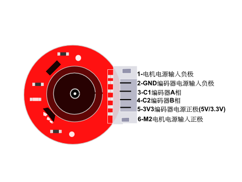
引脚说明

| 标号 | 名称 | 功能描述 |
|---|---|---|
| 1 | 电机电源GND | GND |
| 2 | 编码器电源GND | GND |
| 3 | 编码器A相 | 脉冲A |
| 4 | 编码器B相 | 脉冲B |
| 5 | 编码器电源VCC | 3.3V/5.0V |
| 6 | 电机电源VCC | 6V |
管脚定义
使用教程
下列有两个示例代码,代码1可用来验证电机,也可以了解电机的工作原理;代码2可用来做智能小车等方面应用的基础使用。
准备
- 硬件
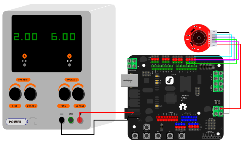
- 1 x Romeo 三合一Arduino兼容控制器(注:短接好各个与电机有关的跳帽)
- 1 x 6V电源
- 若干 杜邦线
- 软件
- Arduino IDE 点击下载Arduino IDE
接线图
电机接线图1(下载示例代码1程序)

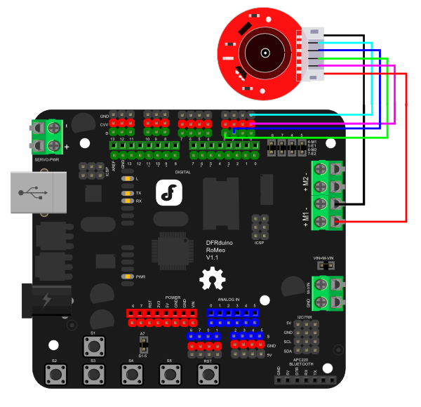
电机接线图2(下载示例代码2程序)
只需将电机的正负极接线接到M1上,其它的包括电源在内的都不变,下载示例代码2程序就可以实现。

本次教程意在编码器的使用上,选用D2和D3两个管脚,其中D2作为了中断口,D3作为信号输入引脚。在实际应用中只需要确保两个管脚中有一个必须是中断管脚即可,另一个可自行定义(参见下图主控的中断管脚)
Interrupt Port with Different Board
Notcie: attachInterrupt()

举个例子,当你想在UNO上面使用中断管脚0(中断0),你可以连接2号数字管脚(D2);使用中断管脚1(中断1),你可以连接3号数字管脚(D3)
样例代码
示例代码1:
/*!
 * @file  FIT052X.ino
 * @brief Metal DC Motor Encoder - 6V
 * @n 数据不断的从串口输出,当电机正转时,输出的数值>0, 电机反向转时,输出数字\<0。
 * @n 并且电机速度越快,数字的绝对值越大,反之越小。
 * @copyright  Copyright (c) 2010 DFRobot Co.Ltd (http://www.dfrobot.com)
 * @license  The MIT License (MIT)
 * @author  DFRobot
 * @version  V1.0
 * @date  2023-08-03
 */

//The sample code for driving one way motor encoder
const byte encoder0pinA = 2;//A pin -> the interrupt pin 0
const byte encoder0pinB = 3;//B pin -> the digital pin 3
byte encoder0PinALast;
int duration;//the number of the pulses
boolean Direction;//the rotation direction


void setup()
{
  Serial.begin(57600);//Initialize the serial port
  EncoderInit();//Initialize the module
}

void loop()
{
  Serial.print("Pulse:");
  Serial.println(duration);
  duration = 0;
  delay(100);
}

void EncoderInit()
{
  Direction = true;//default -> Forward
  pinMode(encoder0pinB, INPUT);
  attachInterrupt(0, wheelSpeed, CHANGE);
}

void wheelSpeed()
{
  int Lstate = digitalRead(encoder0pinA);
  if ((encoder0PinALast == LOW) && Lstate == HIGH) {
    int val = digitalRead(encoder0pinB);
    if (val == LOW && Direction) {
      Direction = false; //Reverse
    } else if (val == HIGH && !Direction) {
      Direction = true;  //Forward
    }
  }
  encoder0PinALast = Lstate;

  if (!Direction)  duration++;
  else  duration--;
}
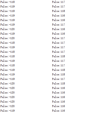
代码1运行现象:
说明:数据不断的从串口输出,当电机正转时,输出的数值>0, 电机反向转时,输出数字<0。并且电机速度越快,数字的绝对值越大,反之越小。

示例代码2(PID控制): 通过L298P直流电机驱动板驱动直流电机,PID算法控制电机的转速。
- 电机电源口连接至L298电机驱动M1口
- 下载并安装Arduino PID库。 如何安装库?
/*!
 * @file  FIT052X.ino
 * @brief Metal DC Motor Encoder - 6V
 * @n 通过L298P直流电机驱动板驱动直流电机,PID算法控制电机的转速。
 * @copyright  Copyright (c) 2010 DFRobot Co.Ltd (http://www.dfrobot.com)
 * @license  The MIT License (MIT)
 * @author  DFRobot
 * @version  V1.0
 * @date  2023-08-03
 */

//The sample code for driving one way motor encoder
#include <PID_v1.h>
const byte encoder0pinA = 2;//A pin -> the interrupt pin 0
const byte encoder0pinB = 3;//B pin -> the digital pin 3
int E_left = 5; //L298P直流电机驱动板的使能端口连接到数字接口5
int M_left = 4; //L298P直流电机驱动板的转向端口连接到数字接口4
byte encoder0PinALast;
double duration, abs_duration;//the number of the pulses
boolean Direction;//the rotation direction
boolean result;

double val_output;//用于提供给电机PWM功率值。
double Setpoint;
double Kp = 0.6, Ki = 5, Kd = 0;
PID myPID(&abs_duration, &val_output, &Setpoint, Kp, Ki, Kd, DIRECT);

void setup()
{
  Serial.begin(9600);//Initialize the serial port
  pinMode(M_left, OUTPUT);   //L298P直流电机驱动板的控制端口设置为输出模式
  pinMode(E_left, OUTPUT);
  Setpoint = 80;  //设置PID的输出值
  myPID.SetMode(AUTOMATIC);//设置PID为自动模式
  myPID.SetSampleTime(100);//设置PID采样频率为100ms
  EncoderInit();//Initialize the module
}

void loop()
{
  advance();//电机正转
  abs_duration = abs(duration);
  result = myPID.Compute();//PID转换完成返回值为1
  if (result) {
    Serial.print("Pluse: ");
    Serial.println(duration);
    duration = 0; //计数清零等待下次计数
  }


}

void EncoderInit()
{
  Direction = true;//default -> Forward
  pinMode(encoder0pinB, INPUT);
  attachInterrupt(0, wheelSpeed, CHANGE);
}

void wheelSpeed()
{
  int Lstate = digitalRead(encoder0pinA);
  if ((encoder0PinALast == LOW) && Lstate == HIGH) {
    int val = digitalRead(encoder0pinB);
    if (val == LOW && Direction) {
      Direction = false; //Reverse
    } else if (val == HIGH && !Direction) {
      Direction = true;  //Forward
    }
  }
  encoder0PinALast = Lstate;

  if (!Direction)  duration++;
  else  duration--;

}

void advance()//电机正转
{
  digitalWrite(M_left, LOW);
  analogWrite(E_left, val_output);
}

void back()//电机反转
{
  digitalWrite(M_left, HIGH);
  analogWrite(E_left, val_output);
}

void Stop()//电机停止
{
  digitalWrite(E_left, LOW);
}
代码2运行现象:
因为程序设定的PID值为80,所以电机会稳定转速在80左右,当外界的力量(比如电机的驱动电压变化,电机受到的阻力变大等)迫使转速改变时,程序会通过PWM调节,使转速稳定在80左右。比如增大电机驱动电压,电机转速会短暂的上升后下降到80,减小电机驱动电压,电机转速会短暂下降后,上升到80。
常见问题
还没有客户对此产品有任何问题,欢迎通过qq或者论坛联系我们!
更多问题及有趣的应用,可以 访问论坛 进行查阅或发帖。 |
