简介
一般来说,温度测量可分为接触式和非接触式,接触式测温只能测量被测物体与测温传感器达到热平衡后的温度,所以响应时间长,且极易受环境温度的影响;而红外测温是根据被测物体的红外辐射能量来确定物体的温度,不与被测物体接触,不影响被测物体温度场,并且温度分辨率高、响应速度快、稳定性好等特点。近年来,非接触红外测温在医疗,环境监测、家庭自动化、汽车电子、航空和军事上得到越来越广泛的应用。
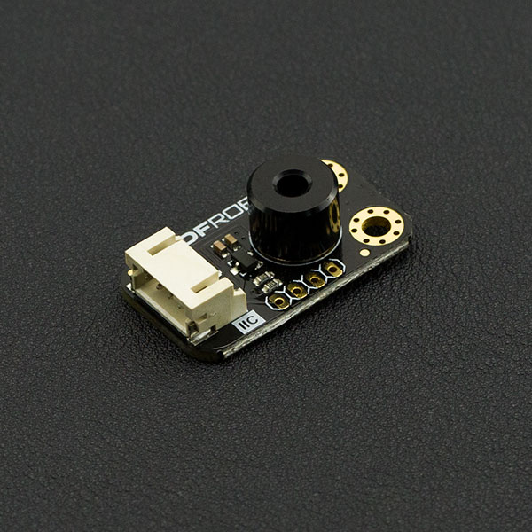
DFRobot 最新推出的MLX90614红外测温模块,通过探测物体红外辐射能量的大小和波长的分布来检测物体的表面温度。红外测温器由光学系统、光电探测器、信号放大器和信号处理及输出等部分组成。光学系统汇聚其视场内的目标红外辐射能量,视场的大小由测温仪的光学零件及其位置确定。红外能量聚焦在光电探测器上并转变为相应的电信号。该信号经过放大器和信号处理电路,并按照仪器内的算法和目标发射率校正后转变为被测目标的温度值。MLX90614出厂自带校准,并且在信号调节芯片中使用了先进的低噪音放大器,一枚17-bit ADC以及功能强大的DSP元件,从而实现高精度温度测量。
产品参数
SEN0206(MLX90614-DCC)
- 工作电压:3.3V-5V
- 工作电流:1.2mA
- 温度范围:-70.01℃至+382.19℃,分辨率0.01℃
- 接口类型:IIC
- 接口线序:VCC,GND,SCL,SDA
- 视场:35°
- 尺寸:31.5mm×18mm
SEN0263(MLX90614-DCI)
- 工作电压:3.3V-5V
- 工作电流:1.2mA
- 温度范围:-70.01℃至+270℃,分辨率0.01℃
- 接口类型:IIC
- 接口线序:VCC,GND,SCL,SDA
- 视场:5°
- 尺寸:31.5mm×18mm
引脚说明
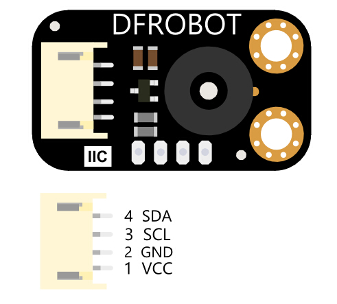
IR Thermometer Sensor-MLX90614接口说明
| 标号 | 名称 | 功能描述 |
|---|---|---|
| 1 | VCC | 电源正极 |
| 2 | GND | 电源负极 |
| 3 | SCL | IIC时钟引脚 |
| 4 | SDA | IIC数据引脚 |
使用教程
准备
- 硬件
- DFRduino UNO x1
- IR Thermometer Sensor-MLX90614 红外温度传感 x1
- 杜邦线 若干
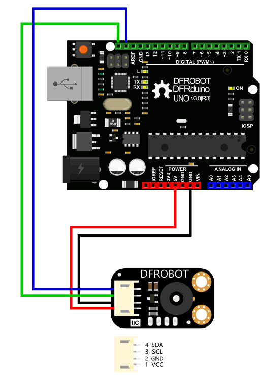
接线图
样例代码1
/*!
 * @file        getData.ino
 * @brief       this demo demonstrates how to put the sensor enter/exit sleep mode and get temperature data measured by sensor
 * @copyright   Copyright (c) 2010 DFRobot Co.Ltd (http://www.dfrobot.com)
 * @license     The MIT License (MIT)
 * @author      [qsjhyy](yihuan.huang@dfrobot.com)
 * @version     V1.0
 * @date        2021-08-09
 * @url         https://github.com/DFRobot/DFRobot_MLX90614
 */
#include <DFRobot_MLX90614.h>

DFRobot_MLX90614_I2C sensor;   // instantiate an object to drive our sensor

void setup()
{
  Serial.begin(115200);

  // initialize the sensor
  while( NO_ERR != sensor.begin() ){
    Serial.println("Communication with device failed, please check connection");
    delay(3000);
  }
  Serial.println("Begin ok!");

  /**
   * adjust sensor sleep mode
   * mode select to enter or exit sleep mode, it's enter sleep mode by default
   *      true is to enter sleep mode
   *      false is to exit sleep mode (automatically exit sleep mode after power down and restart)
   */
  sensor.enterSleepMode();
  delay(50);
  sensor.enterSleepMode(false);
  delay(200);
}

void loop()
{
  /**
   * get ambient temperature, unit is Celsius
   * return value range: -40.01 °C ~ 85 °C
   */
  float ambientTemp = sensor.getAmbientTempCelsius();

  /**
   * get temperature of object 1, unit is Celsius
   * return value range:
   * @n  -70.01 °C ~ 270 °C(MLX90614ESF-DCI)
   * @n  -70.01 °C ~ 380 °C(MLX90614ESF-DCC)
   */
  float objectTemp = sensor.getObjectTempCelsius();

  // print measured data in Celsius
  Serial.print("Ambient celsius : "); Serial.print(ambientTemp); Serial.println(" °C");
  Serial.print("Object celsius : ");  Serial.print(objectTemp);  Serial.println(" °C");

  // print measured data in Fahrenheit
  Serial.print("Ambient fahrenheit : "); Serial.print(ambientTemp*9/5 + 32); Serial.println(" F");
  Serial.print("Object fahrenheit : ");  Serial.print(objectTemp*9/5 + 32);  Serial.println(" F");

  Serial.println();
  delay(500);
}
样例代码2
/*!
 * @file        setSensor.ino
 * @brief       this demo is to set the emissivity calibration coefficient, and set measurement parameters, including IIR, FIR and measurement objects
 * @copyright   Copyright (c) 2010 DFRobot Co.Ltd (http://www.dfrobot.com)
 * @license     The MIT License (MIT)
 * @author      [qsjhyy](yihuan.huang@dfrobot.com)
 * @version     V1.0
 * @date        2021-08-09
 * @url         https://github.com/DFRobot/DFRobot_MLX90614
 */
#include <DFRobot_MLX90614.h>

#define MLX90614_I2C_ADDR 0x5A   // mlx9614 default I2C communication address
DFRobot_MLX90614_I2C sensor(MLX90614_I2C_ADDR, &Wire);   // instantiate an object to drive the sensor

void setup()
{
  Serial.begin(115200);

  // initialize the sensor
  while( NO_ERR != sensor.begin() ){
    Serial.println("Communication with device failed, please check connection");
    delay(3000);
  }
  Serial.println("Begin ok!");

  /**
   * set the emissivity calibration coefficient, users need to calculate the ratio of the temperature measured before the sensor changes emissivity to the true temperature of the object,
   * upload the ratio to the api as a parameter, and the deviation of the object absolute temperature measured by the sensor will be lower
   * calibrationValue new calibration coefficient, [0, 1]
   */
  sensor.setEmissivityCorrectionCoefficient(1.0);

  /**
   * set I2C communication address, the setting takes effect after power down and restart
   * addr new I2C communication address 7bit(0~127)
   */
  sensor.setI2CAddress(0x5A);

  /**
   * set the measurement parameters, including IIR (Infinite Impulse Response Digital Filter) and FIR (Finite Impulse Response Digital Filter)
   * IIRMode: eIIR100, eIIR80, eIIR67, eIIR57;
   * FIRMode: eFIR128, eFIR256, eFIR512, eFIR1024;
   */
   sensor.setMeasuredParameters(sensor.eIIR100, sensor.eFIR1024);

  /**
   * control the sensor sleep mode, must enter and exit the sleep mode once after the sensor is configured (equivalent to soft reset) to ensure the normal reading of the measured data
   * mode select to enter or exit sleep mode, it's enter sleep mode by default
   *      true put the sensor to sleep
   *      false wake up the sensor (automatically exit sleep mode after power down and restart)
   */
  sensor.enterSleepMode();
  delay(50);
  sensor.enterSleepMode(false);
  delay(200);
}

void loop()
{
  /**
   * get ambient temperature, unit is Celsius
   * return value range: -40.01 °C ~ 85 °C
   */
  float ambientTemp = sensor.getAmbientTempCelsius();

  /**
   * get temperature of object 1, unit is Celsius
   * return value range:
   * @n  -70.01 °C ~ 270 °C(MLX90614ESF-DCI)
   * @n  -70.01 °C ~ 380 °C(MLX90614ESF-DCC)
   */
  float objectTemp = sensor.getObjectTempCelsius();

  // print measured data in Celsius, unit is Celsius (°C)
  Serial.print("Ambient celsius : "); Serial.print(ambientTemp); Serial.println(" °C");
  Serial.print("Object celsius : ");  Serial.print(objectTemp);  Serial.println(" °C");

  // print measured data in Fahrenheit, unit is Fahrenheit (F)
  Serial.print("Ambient fahrenheit : "); Serial.print(ambientTemp*9/5 + 32); Serial.println(" F");
  Serial.print("Object fahrenheit : ");  Serial.print(objectTemp*9/5 + 32);  Serial.println(" F");

  Serial.println();
  delay(500);
}
测量方法
使用红外测温模块,需要先引入一个概念——“视场 (FOV)”。 视场是由温差电堆接收到50%的辐射信号来确定的,并且和传感器的主轴线相关。如下图所示。标明视场角(FOV)大小。测量得到的温度其实是视场内被测物体的温度加权平均值,只有在被测物体完全覆盖红外传感器的FOV视场才能保证精度。所以在实际应用中必须保证测温点终端与被测母线之间的距离满足要求才能保障测温的精度要求。
SEN0206模块的视场为35°FOV,tan35°=被测物体半径÷红外传感器与被测物体之间的距离,例:被测物体的半径为5cm,这测量距离为7cm(在此范围内测试的温度最准确)。下图为此传感器的FOV图:

被测点需要全部处在视场内
SEN0263模块的视场为5°FOV,tan5°=被测物体半径÷红外传感器与被测物体之间的距离,例:被测物体的半径为5cm,这测量距离为57cm(在此范围内测试的温度最准确)。下图为此传感器的FOV图:
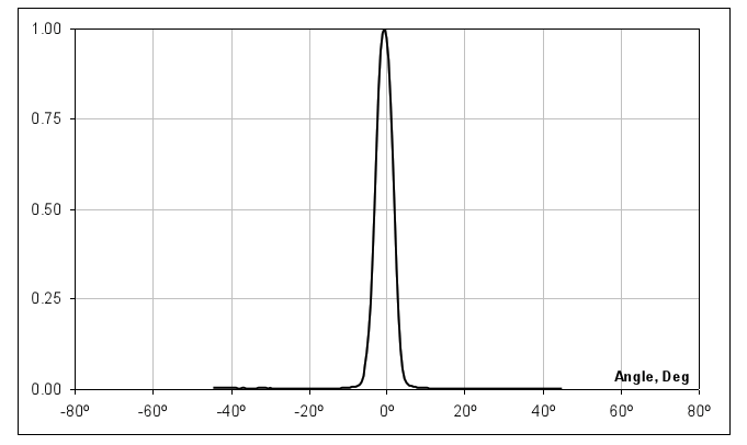
被测点需要全部处在视场内
结果
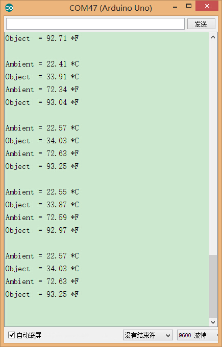
IR Thermometer Sensor-MLX90614测试结果
MLX90614发射率补偿方法
MLX90614如何进行发射率补偿?
什么时候需要改变发射率?
发射率就是显示物体发射IR的能力与理论绝对黑体发射能力的比值。MLX90614使用这个比率来计算物体的温度。在生产时,MLX90614在发射率为99.9%的黑体前进行校准,将该发射率定义为E=1。
不同的材料有不同的发射率,为了精确地测量温度,应该更新发射率系数到MLX90614的EEPROM中。
因此当IR辐射在以下几种方式减少时,需要一些通常的规则来补偿。例如:
1、由于低发射率的物体
2、由于IR传输材料(穿透率小于1)放在MLX90614前面
如何确定新的发射率E
为了确定新的发射率,我们应该更新MLX90614的EEPROM,需要做以下测试(使用传输材料与不同的发射率)。确保在测试这前,器件内部的发射率为E=1
当传输材料介于传感器和被测物体之间
我们可以使用MLX90614来检测原始的温度(发射率E=1),在传输材料未放在MLX90614与被测物体间之前。步骤如下:
1)加热被测物体到一个不等于环境温度的温度值。假设To=60℃(注意这个温度必须保持稳定)。被测物体与传感器的温度差应该至少为30℃。
2)开始测量并记录数据Treal=60℃、Ta_real=25℃(这些温度值为假设值)
3)放置传输材料在MLX90614前面(注:为了正常的测量,传输材料的温度必须与MLX90614的温度一样。否则MLX90614将会看到传输材料的温度,这将会引入错误)
4)再次用MLX90614进行测量,并记录数据,如Tnew =50℃、Ta_new =25℃(通常环境温以应该一样)。
当物体的发射率不等于1
为了计算新发射率的值,我们需要被测物体真实的温度值。通常有两种方法来测量温度:
1、使用精确的接触式温度计测量温度。
2、物体喷漆的部分(喷漆的发射率应该为1),因此可以用MLX90614来测量这个喷漆点(注意喷漆点必须大于MLX90614的FOV)步聚如下:
1)加热被测物体到一个不等于环境温度的温度值。假设To=60℃(注意这个温度必须保持稳定)。
2)使用上面的方法检查真实的温度,假设Treal=60℃,并记录MLX90614测得的环境温度Ta_real=25℃(这些温度仅仅只是举例)。
3)使用MLX90614测量物体的温度,并记录Tnew=40℃,Ta_new=25℃(通常环境温度应该一样)。
4)计算新的发射率系数:(注:温度使用开尔文)
Mind+ 上传模式编程
- 下载及安装软件。下载地址:https://www.mindplus.cc 详细教程:Mind+基础wiki教程-软件下载安装
- 切换到“上传模式”。 详细教程:Mind+基础wiki教程-上传模式编程流程
- “扩展”中选择“主控板”中的“Arduino Uno”。 "扩展"“传感器”中搜索选择“非接触式红外温度传感器”。详细教程:Mind+基础wiki教程-加载扩展库流程
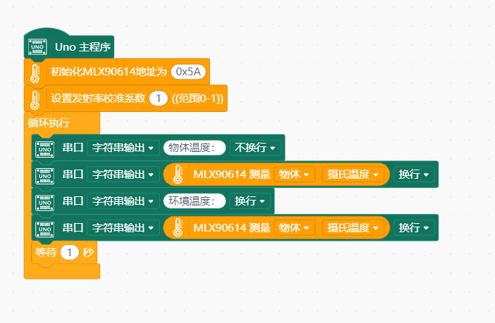
- 进行编程,程序如下图:
- 菜单“连接设备”,“上传到设备”
- 程序上传完毕后,打开串口即可看到数据输出。详细教程:Mind+基础wiki教程-串口打印
Mind+ Python模式编程(行空板)
Mind+Python模式为完整Python编程,因此需要能运行完整Python的主控板,此处以行空板为例说明
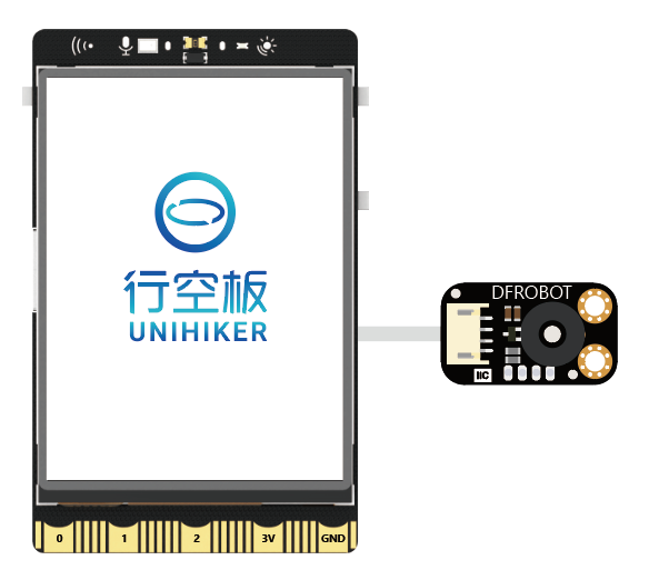
连接图
操作步骤
1、下载及安装官网最新软件。下载地址:https://www.mindplus.cc 详细教程:Mind+基础wiki教程-软件下载安装
2、切换到“Python模式”。“扩展”中选择“官方库”中的“行空板”和“pinpong库”中的”pinpong初始化“和“非接触式红外温度传感器”。切换模式和加载库的详细操作链接
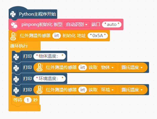
3、进行编程
4、连接行空板,程序点击运行后,可在终端查看数据。行空板官方文档-行空板快速上手教程 (unihiker.com)
代码编程
以pinpong库为例,行空板官方文档-行空板快速上手教程 (unihiker.com)
#  -*- coding: UTF-8 -*-

# MindPlus
# Python
from pinpong.libs.dfrobot_mlx90614 import MLX90614
from pinpong.board import Board
import time


Board().begin()
irt = MLX90614(0x5A)

while True:
    print("物体温度:")
    print(irt.obj_temp_c())
    print("环境温度:")
    print(irt.env_temp_c())
    time.sleep(1)
常见问题
还没有客户对此产品有任何问题,欢迎通过qq或者论坛联系我们!
更多问题及有趣的应用,可以 访问论坛 进行查阅或发帖!
