概述
DFRduino RoMeo控制器是一个兼容Arduino的专为机器人应用而设计的,受益Arduino开源平台,因此受到成千上万的开放源码的支持,并可以很容易地扩展arduino模块。
集成2路直流电动机驱动器和无线插座,给出了一个更简单容易的方式开始你的机器人项目。
性能描述
- Atmega 328
- 14 通道数字 I/O
- 6 PWM 通道 (Pin11,Pin10,Pin9,Pin6,Pin5,Pin3)
- 8通道10位模拟I / O
- USB接口
- 自动切换输入电源
- ICSP下载程序接口
- 串行接口TTL电平
- 支持AREF
- 具有排母和排针接口
- 具有APC220射频模块和DF-蓝牙模块插座
- 具有3个I2C接口
- 2个2A大电流的H桥马达驱动器
- 模拟5键输入
- 直流电源:USB供电或外部7V〜12V直流。
- DC输出:5V/3.3V直流外接电源输出
- 尺寸:90x80mm
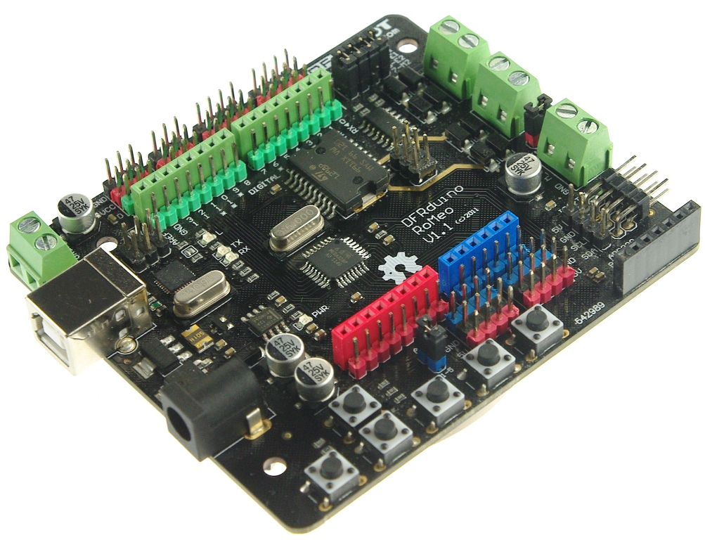
管脚定义
 上面的图片显示RoMeo控制器上所有的I/O线和连接器,其中包括:
- 调速电机电源输入端子(6V to12v)
- 一个非稳压伺服电源输入端子(5V至20V)
- 一个串行接口APC220/Bluetooth模块的模块头
- 两个直流电动机的接线端子 - 把手电机电流绘制高达2A,每个终端
- 一个I2C/TWI接口的SDA,SCL的,5V,接地
- 内部连接到一个模拟端口,8个模拟输入 - 输入电源电压
- 一个通用的I/O端口和13个I/O线 - 4,5,6,7可用于控制马达
- 一个复位按键
- 启用/禁用电机控制跳线
注意:使用USB口调试电机的时候,请关闭电机开关!
新版本驱动安装教程
2021年2月份之后购买的产品,请使用以下方式安装驱动后再使用。
⚠注意:OSX和Linux不需要安装驱动,只需要安装开发板;Windows需要安装驱动和开发板。
1.安装板子
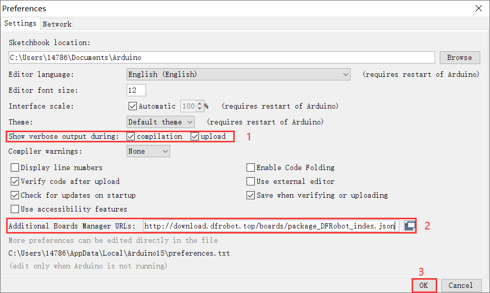
(1)打开 Arduino 1.8.13,点击File——Preferences——Show verbose output during中勾选compilation和upload,再把json文件网址(如下所示)复制粘贴到Addi tional Boards Manager URLs中,然后点击页面右下角的OK关闭页面。
https://downloadcd.dfrobot.com.cn/boards/package_DFRobot_index.json
(2)点击Tools——Board——Boards Manager——选择DFRobot AVR Boards板子——点击Install——安装完成后点击右下角Close关闭页面。
2、安装驱动
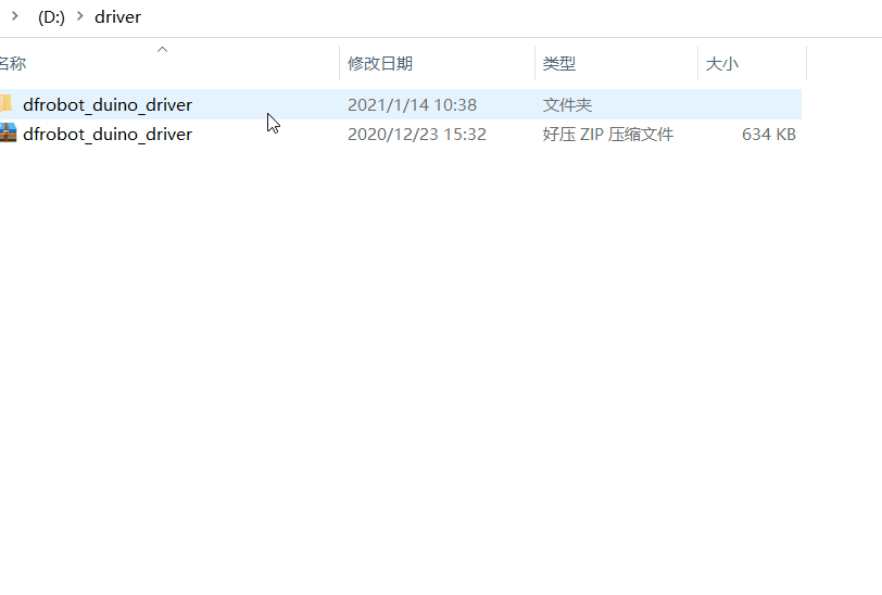
(1)下载驱动并安装
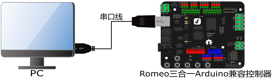
(2)用串口线连接Romeo三合一Arduino兼容控制器和pc
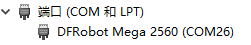
(3)打开设备管理器查看端口号(与下图显示一样即驱动安装成功)
控制器应用
电源
这是RoMeo控制器与主机控制器通信的最重要步骤之一。你必须确保你接通电源的电力终端使用正确的极性。反接会损坏RoMeo控制器。 “人为造成损坏我们将不负责保修,可以提供有偿维修。请确保你使用正确适用的电源。否则,后果自负!”
从USB电源: 只需插上USB线,RoMeo控制器就能够工作。请注意,USB只能提供500毫安的电流。它应该能够满足大多数需求,比如LED背光应用。然而,它是没有足够的功率推动直流电动机或伺服。
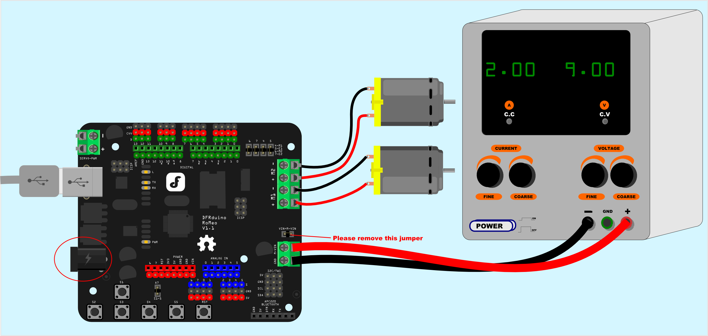
电机电源输入: 你可以从Motor Power In的接线柱端子连接线,标示“M_VIN”为电源正,当电机电源小于12V时,控制器可以和电机共用一个电源,Power In Selection Jumper短路帽插上;当电机电源大于12V时,Power In Selection Jumper短路帽必须断开,同时控制器需要单独供电。
注意:最大供电电压不能超过24V直流
软件
RoMeo控制器可以使用编程环境Arduino IDE 0022及以上。 您可以在Arduino.cc下载,请选择“硬件”的Arduino UNO“。
RoMeo配置
伺服电源选择跳线
由于大多数舵机电流大于USB电源可提供的电流。所以设计有1个独立的舵机供电接线端口(Servo Power)。
当Servo Power端口接电源大于5V时,数字口电源将自动断开控制器的5V供电。
Romeo 1.0以下版使用的电源手动切换。需要插拔跳线来切换外部电源还是内部电源供电
电机控制针跳线
电机控制针跳线,将分配用于电机控制引脚为数字口4,5,6,7(老版本Romeo是6,7,8,9)。
拔掉跳线将释放数字口,电机控制器将被禁用。
模拟口7按键跳线
模拟口7号口默认为板载按键S1-S5输入接口,如果需要使用模拟口7的模拟输入功能,需要拔掉A7标识的跳线帽。
教程
按钮
RoMeo控制器有5个按钮:S1-S5(图2)。 S1-S5占用模拟输入引脚7,使用A7跳线帽切换(插上跳线帽可以使用模拟口7读取按键,拔掉跳线帽可以使用模拟口7读取模拟输入)。
| 引脚 | 功能 |
|---|---|
| 模拟引脚 7 | 按键 S1-S5 |
"按键引脚图"

按键1-5使用范例
char msgs[5][15] = {
  "Right Key OK ",
  "Up Key OK    ",
  "Down Key OK  ",
  "Left Key OK  ",
  "Select Key OK" };
char start_msg[15] = {
  "Start loop "};
int  adc_key_val[5] ={
  30, 150, 360, 535, 760 };
int NUM_KEYS = 5;
int adc_key_in;
int key=-1;
int oldkey=-1;
void setup() {
  pinMode(13, OUTPUT);  //we'll use the debug LED to output a heartbeat
  Serial.begin(9600);

  /* Print that we made it here */
  Serial.println(start_msg);
}

void loop()
{
  adc_key_in = analogRead(7);    // read the value from the sensor
  digitalWrite(13, HIGH);
  /* get the key */
  key = get_key(adc_key_in);    // convert into key press
  if (key != oldkey) {   // if keypress is detected
    delay(50);      // wait for debounce time
    adc_key_in = analogRead(7);    // read the value from the sensor
    key = get_key(adc_key_in);    // convert into key press
    if (key != oldkey) {
      oldkey = key;
      if (key >=0){
        Serial.println(adc_key_in, DEC);
        Serial.println(msgs[key]);
      }
    }
  }
  digitalWrite(13, LOW);
}
// Convert ADC value to key number
int get_key(unsigned int input)
{
  int k;
  for (k = 0; k < NUM_KEYS; k++)
  {
    if (input < adc_key_val[k])
    {
      return k;
    }
  }
  if (k >= NUM_KEYS)
    k = -1;     // No valid key pressed
  return k;
}
双直流电动机调速
硬件设置
连接四个电机电线到电机端子。并通过电机功率电源端子供电(图4)。
引脚分配
| 引脚 | 功能 |
|---|---|
| 4 | 电机1方向控制 |
| 5 | 电机1PWM控制 |
| 6 | 电机2PWM控制 |
| 7 | 电机2方向控制 |
"PWM模式"
| 引脚 | 功能 |
|---|---|
| 4 | 电机1启用控制 |
| 5 | 电机1方向控制 |
| 6 | 电机2方向控制 |
| 7 | 电机2启用控制 |
"PLL模式"
PWM控制模式

通过改变两个数字IO引脚和两个PWM引脚的PWM对直流电动机控制端口实现。见上面的图(图5),4,7引脚(老版本Romeo的7,8)电机方向控制引脚,引脚5,6(老版本Romeo的6,9)电机转速控制引脚。
“老版本RoMeo控制器板,用于控制电机的引脚是引脚7,8(方向),6,9引脚(速度)。你可以找到的信息,在右侧的马达控制针跳线。
Sample Code:
//Standard PWM DC control
int E1 = 5;     //M1 Speed Control
int E2 = 6;     //M2 Speed Control
int M1 = 4;    //M1 Direction Control
int M2 = 7;    //M1 Direction Control

///For previous Romeo, please use these pins.
//int E1 = 6;     //M1 Speed Control
//int E2 = 9;     //M2 Speed Control
//int M1 = 7;    //M1 Direction Control
//int M2 = 8;    //M1 Direction Control


void stop(void)                    //Stop
{
  digitalWrite(E1,LOW);
  digitalWrite(E2,LOW);
}
void advance(char a,char b)          //Move forward
{
  analogWrite (E1,a);      //PWM Speed Control
  digitalWrite(M1,HIGH);
  analogWrite (E2,b);
  digitalWrite(M2,HIGH);
}
void back_off (char a,char b)          //Move backward
{
  analogWrite (E1,a);
  digitalWrite(M1,LOW);
  analogWrite (E2,b);
  digitalWrite(M2,LOW);
}
void turn_L (char a,char b)             //Turn Left
{
  analogWrite (E1,a);
  digitalWrite(M1,LOW);
  analogWrite (E2,b);
  digitalWrite(M2,HIGH);
}
void turn_R (char a,char b)             //Turn Right
{
  analogWrite (E1,a);
  digitalWrite(M1,HIGH);
  analogWrite (E2,b);
  digitalWrite(M2,LOW);
}
void setup(void)
{
  int i;
  for(i=4;i<=7;i++)
    pinMode(i, OUTPUT);
  Serial.begin(19200);      //Set Baud Rate
  Serial.println("Run keyboard control");
}
void loop(void)
{
  if(Serial.available()){
    char val = Serial.read();
    if(val != -1)
    {
      switch(val)
      {
      case 'w'://Move Forward
        advance (255,255);   //move forward in max speed
        break;
      case 's'://Move Backward
        back_off (255,255);   //move back in max speed
        break;
      case 'a'://Turn Left
        turn_L (100,100);
        break;
      case 'd'://Turn Right
        turn_R (100,100);
        break;
      case 'z':
        Serial.println("Hello");
        break;
      case 'x':
        stop();
        break;
      }
    }
    else stop();
  }
}
PLL控制模式
Romeo也支持PLL[相位锁相环]控制模式。
- 实际使用效果为:
- 启动控制引脚输出高电平电机才能启动,为低电平时则电机禁止启动;
- 方向控制引脚pwm信号为中位值时(约100左右,不同电机需要测试得出),电机停止;
- 方向控制引脚pwm信号偏离中位值越多速度越大;
- 方向控制引脚pwm信号大于中位值正转,小于中位值则反转。
| 引脚 | 功能 |
|---|---|
| 4 | 电机1启用控制 |
| 5 | 电机1方向控制 |
| 6 | 电机2方向控制 |
| 7 | 电机2启用控制 |
"PLL模式"

Sample Code:
    //Standard DLL Speed control

    int E1 = 4;     //M1 Speed Control
    int E2 = 7;     //M2 Speed Control
    int M1 = 5;    //M1 Direction Control
    int M2 = 6;    //M1 Direction Control

    ///For previous Romeo, please use these pins.
    //int E1 = 6;     //M1 Speed Control
    //int E2 = 9;     //M2 Speed Control
    //int M1 = 7;    //M1 Direction Control
    //int M2 = 8;    //M1 Direction Control

    //When m1p/m2p is 127, it stops the motor
    //when m1p/m2p is 255, it gives the maximum speed for one direction
    //When m1p/m2p is 0, it gives the maximum speed for reverse direction

    void DriveMotorP(byte m1p, byte m2p)//Drive Motor Power Mode
    {

      digitalWrite(E1, HIGH);
      analogWrite(M1, (m1p));

      digitalWrite(E2, HIGH);
      analogWrite(M2, (m2p));

    }

    void setup(void)
    {
      int i;
      for(i=6;i<=9;i++)
        pinMode(i, OUTPUT);
      Serial.begin(19200);      //Set Baud Rate
    }
    void loop(void)
    {
      if(Serial.available()){
        char val = Serial.read();
        if(val!=-1)
        {
          switch(val)
          {
          case 'w'://Move Forward
            DriveMotorP(0xff,0xff); // Max speed
            break;
          case 'x'://Move Backward
            DriveMotorP(0x00,0x00);
            ; // Max speed
            break;
          case 's'://Stop
            DriveMotorP(0x7f,0x7f);
            break;

          }
        }
      }
    }
疑难解答
**问:**端口号不显示怎么解决?
**-答:**重新下载并安装驱动。
更多问题及有趣的应用,可以访问论坛进行查阅或发帖!
更多资料
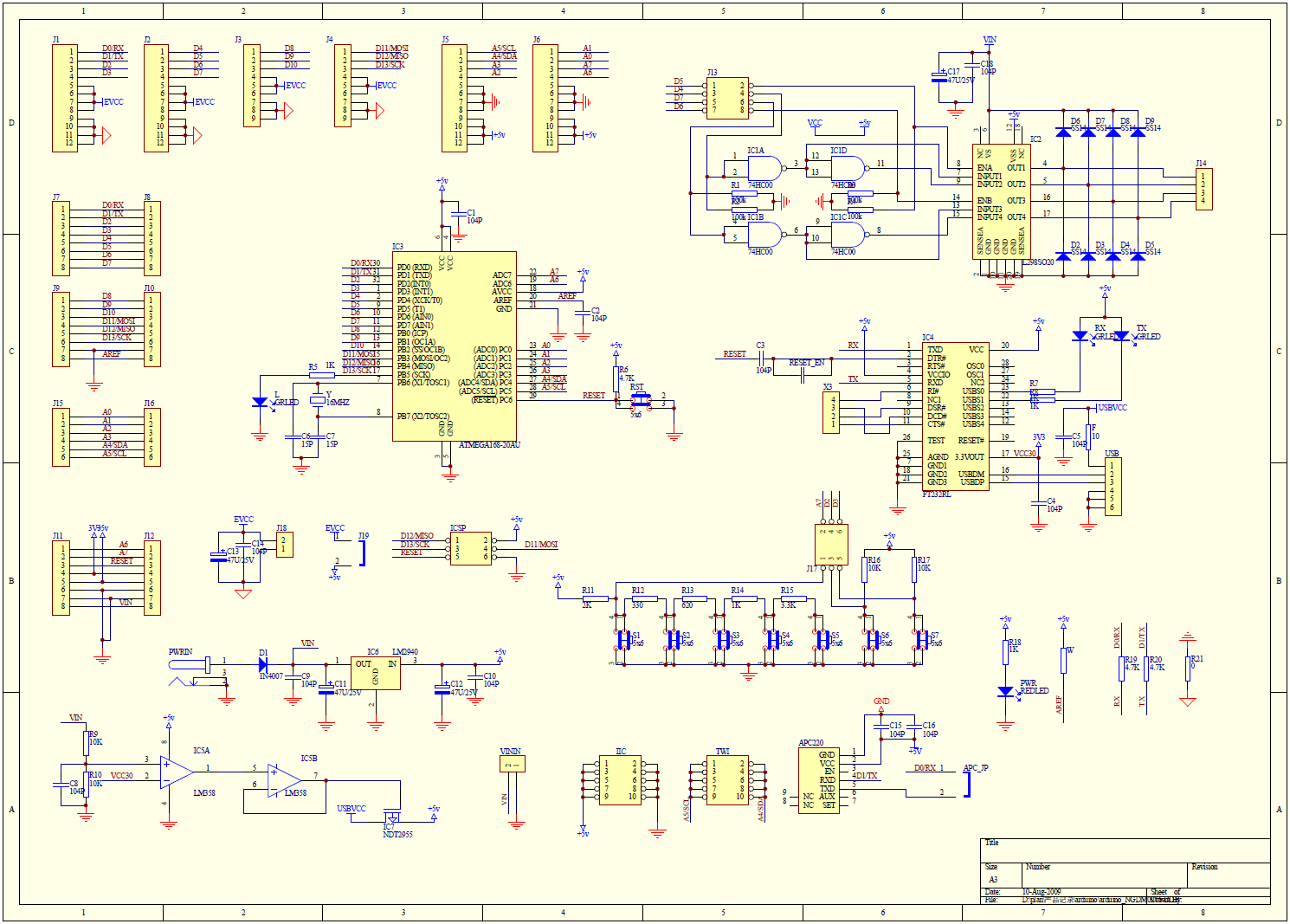
- Romeo schematic V1.3
- Romeo layout plan V1.3
- Romeo schematic V1.1
- Romeo Schematic V1.0
- Romeo Schematic V0.9
