
简介
TDS(Total Dissolved Solids),中文名总溶解固体,又称溶解性固体总量,表明1升水中溶有多少毫克溶解性固体。一般来说,TDS值越高,表示水中含有的溶解物越多,水就越不洁净。因此,TDS值的大小,可作为反映水的洁净程度的依据之一。
常用的TDS检测设备为TDS笔,虽然价格低廉,简单易用,但不能把数据传给控制系统,做长时间的在线监测,并做水质状况分析。使用专门的仪器,虽然能传数据,精度也高,但价格很贵。为此,我们专门推出了这款arduino兼容的TDS传感器,连接至arduino控制器后,就可用于测量水的TDS值。
该产品专为arduino设计,即插即用,使用简单方便。3.3~5.5V的宽电压供电,0~2.3V的模拟信号输出,使得这款产品兼容5V、3.3V控制系统,能非常方便的接到现成的控制系统中使用。测量用的激励源采用交流信号,可有效防止探头极化,延长探头寿命的同时,也增加了输出信号的稳定性。TDS探头为防水探头,可长期浸入水中测量。
该产品可应用于生活用水、水培等领域的水质检测。有了这个传感器,就可轻松DIY一套TDS检测仪了,轻松检测水的洁净程度,为你的水质把好关。
产品参数
信号转接板
- 输入电压:3.3~5.5V
- 输出信号:0~2.3V
- 工作电流: 3~6mA
- TDS测量范围:0~1000ppm
- TDS测量精度:±10% F.S.(25℃)
- 尺寸:42*32mm
- 模块接口:PH2.0-3P
- 电极接口:XH2.54-2P
TDS探头
- 探针数量:2
- 总体长度:83cm
- 连线接口:XH2.54-2P
- 颜色:黑色
- 其他:防水探头
引脚说明
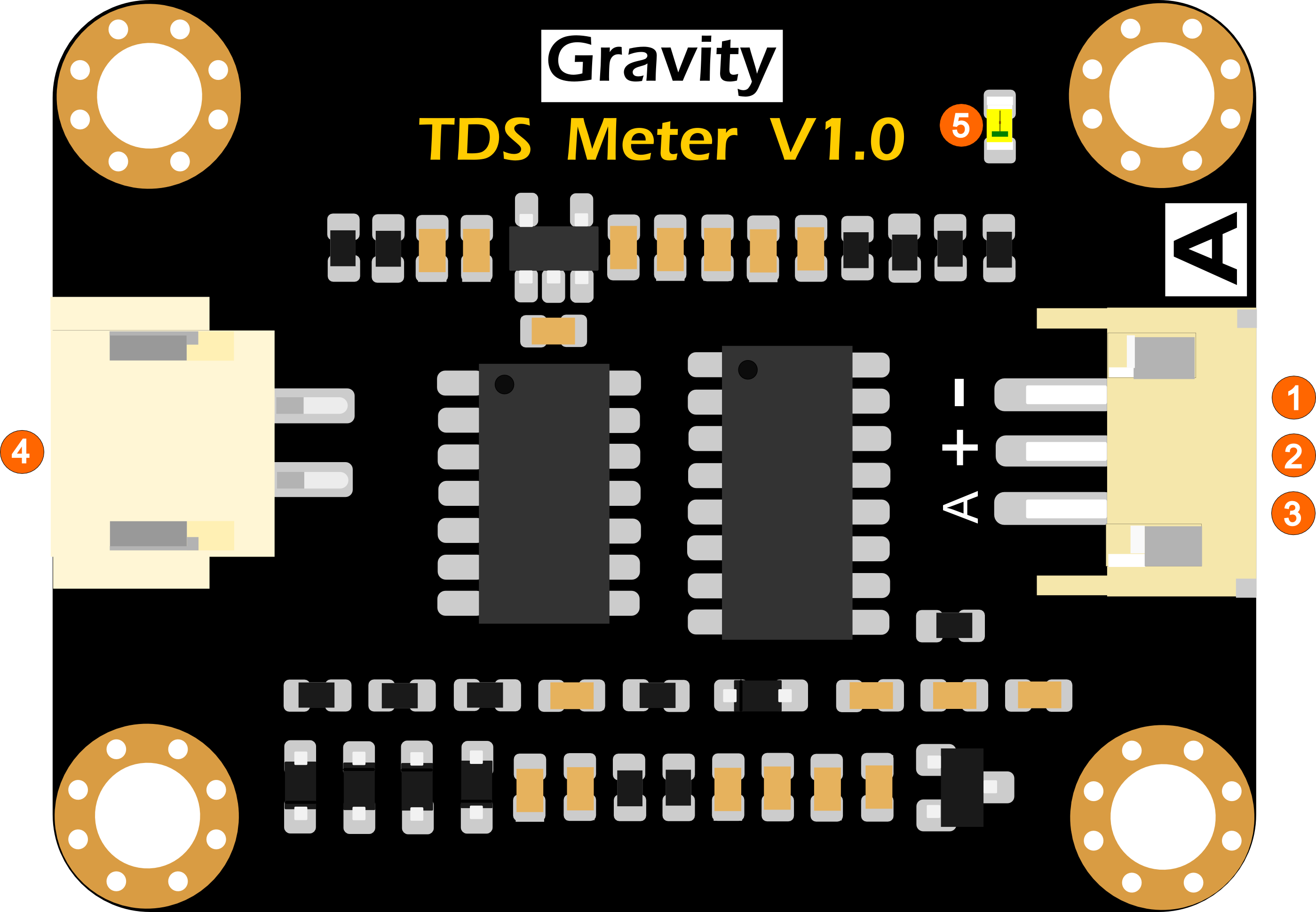
TDS传感器信号转接板管脚定义
| 标号 | 名称 | 功能描述 |
|---|---|---|
| 1 | - | 电源输入负极 |
| 2 | + | 电源输入正极(3.3~5.5V) |
| 3 | A | 模拟信号输出端(0~2.3V) |
| 4 | Probe | TDS探头接口 |
| 5 | LED | 电源指示灯 |
基础教程
本教程将演示如何使用这款产品测量水的TDS值。请认真阅读本教程,注意步骤与细节。

- TDS探头不能用于55℃以上的水中。
- TDS探头放置位置不能太靠近容器边缘,否则会影响示数。
- TDS探头头部与导线为防水,可浸入水中,但连线接口处与信号转接板不防水,请注意使用。
准备
- 硬件
- 1 x ArduinoUNO控制板(或类似的控制板)
- 1 x TDS传感器信号转接板
- 1 x TDS探头
- 1 x 被测溶液
- 1 x 3PIN传感器连接线(或若干 杜邦线)
- 软件
- Arduino IDE V1.0.x 或 Arduino IDE V1.6.x 或 Arduino IDE V1.8.x (点击下载Arduino IDE)
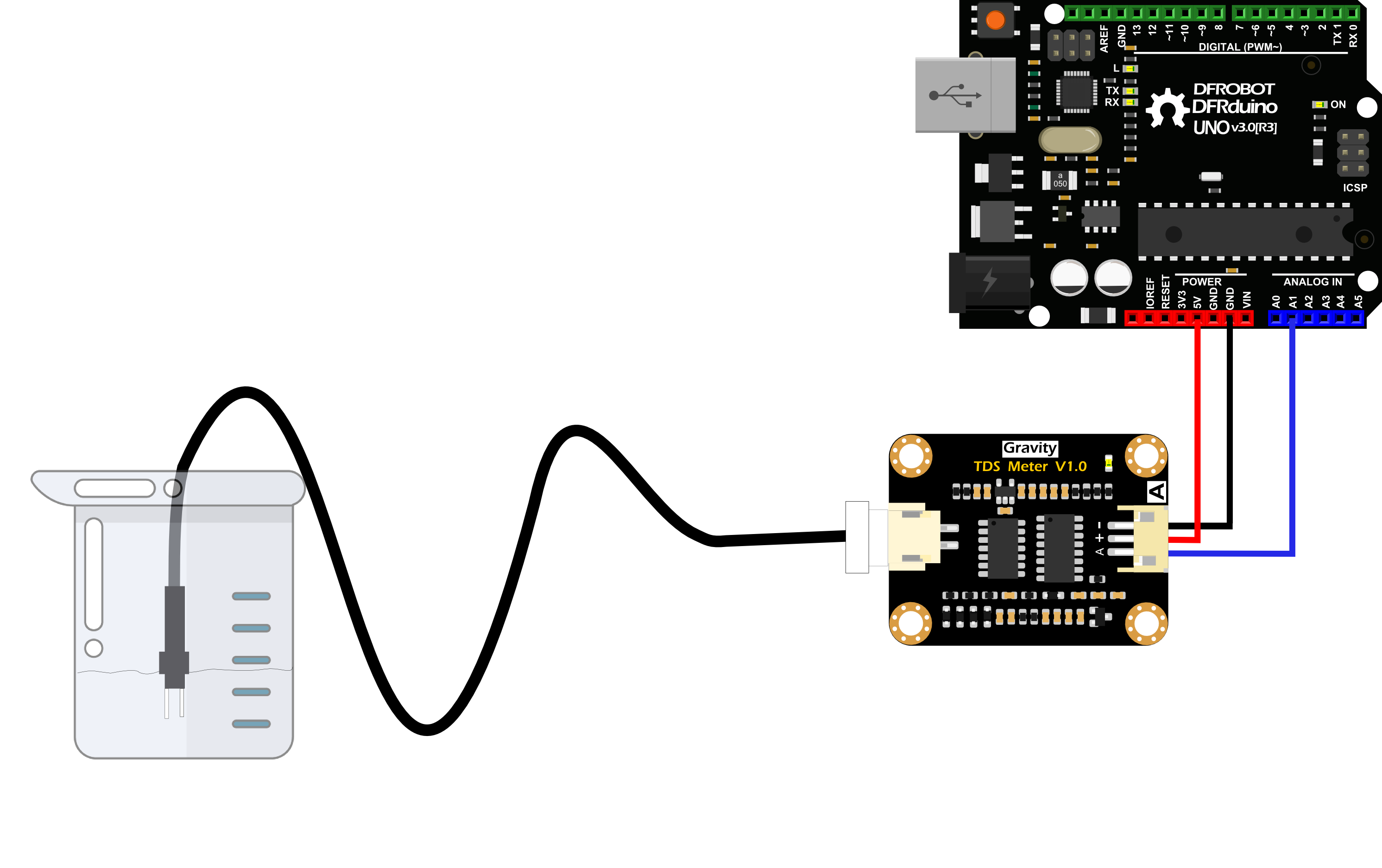
接线图
如下图所示,先将TDS探头接到信号转接板上,再将信号转接板与Arduino主控器连接。连线完毕后,上传样例代码至Arduino主控器。
样例代码
/***************************************************
     DFRobot Gravity: Analog TDS Sensor / Meter For Arduino
     <https://www.dfrobot.com/wiki/index.php/Gravity:_Analog_TDS_Sensor_/_Meter_For_Arduino_SKU:_SEN0244>

     Created 2017-8-22
     By Jason <jason.ling@dfrobot.com@dfrobot.com>

     GNU Lesser General Public License.
     See <https://www.gnu.org/licenses/> for details.
     All above must be included in any redistribution

     /***********Notice and Trouble shooting***************
     1. This code is tested on Arduino Uno and Leonardo with Arduino IDE 1.0.5 r2 and 1.8.2.
     2. More details, please click this link: <https://www.dfrobot.com/wiki/index.php/Gravity:_Analog_TDS_Sensor_/_Meter_For_Arduino_SKU:_SEN0244>
     ****************************************************/

#define TdsSensorPin A1 //analog pin of UNO R3
#define VREF 5.0      // analog reference voltage(Volt) of the UNO R3 ADC
#define ADCRes 1024  //ADC resolution of UNO R3
#define SCOUNT  30           // sum of sample point
int analogBuffer[SCOUNT];    // store the analog value in the array, read from ADC
int analogBufferTemp[SCOUNT];
int analogBufferIndex = 0, copyIndex = 0;
float averageVoltage = 0, tdsValue = 0, temperature = 25;

void setup()
{
  Serial.begin(115200);
  pinMode(TdsSensorPin, INPUT);
}

void loop()
{
  static unsigned long analogSampleTimepoint = millis();
  if (millis() - analogSampleTimepoint > 40U)  //every 40 milliseconds,read the analog value from the ADC
  {
    analogSampleTimepoint = millis();
    analogBuffer[analogBufferIndex] = analogRead(TdsSensorPin);    //read the analog value and store into the buffer
    analogBufferIndex++;
    if (analogBufferIndex == SCOUNT)
      analogBufferIndex = 0;
  }
  static unsigned long printTimepoint = millis();
  if (millis() - printTimepoint > 800U)
  {
    printTimepoint = millis();
    for (copyIndex = 0; copyIndex < SCOUNT; copyIndex++)
      analogBufferTemp[copyIndex] = analogBuffer[copyIndex];
    averageVoltage = getMedianNum(analogBufferTemp, SCOUNT) * (float)VREF / ADCRes; // read the analog value more stable by the median filtering algorithm, and convert to voltage value
    float compensationCoefficient = 1.0 + 0.02 * (temperature - 25.0); //temperature compensation formula: fFinalResult(25^C) = fFinalResult(current)/(1.0+0.02*(fTP-25.0));
    float compensationVolatge = averageVoltage / compensationCoefficient; //temperature compensation
    tdsValue = (133.42 * compensationVolatge * compensationVolatge * compensationVolatge - 255.86 * compensationVolatge * compensationVolatge + 857.39 * compensationVolatge) * 0.5; //convert voltage value to tds value
    //Serial.print("voltage:");
    //Serial.print(averageVoltage,2);
    //Serial.print("V   ");
    Serial.print("TDS Value:");
    Serial.print(tdsValue, 0);
    Serial.println("ppm");
  }
}
int getMedianNum(int bArray[], int iFilterLen)
{
  int bTab[iFilterLen];
  for (byte i = 0; i < iFilterLen; i++)
    bTab[i] = bArray[i];
  int i, j, bTemp;
  for (j = 0; j < iFilterLen - 1; j++)
  {
    for (i = 0; i < iFilterLen - j - 1; i++)
    {
      if (bTab[i] > bTab[i + 1])
      {
        bTemp = bTab[i];
        bTab[i] = bTab[i + 1];
        bTab[i + 1] = bTemp;
      }
    }
  }
  if ((iFilterLen & 1) > 0)
    bTemp = bTab[(iFilterLen - 1) / 2];
  else
    bTemp = (bTab[iFilterLen / 2] + bTab[iFilterLen / 2 - 1]) / 2;
  return bTemp;
}
结果
样例代码上传完毕后,打开Arduino IDE的串口监视器。将TDS探头插入需要测量的水中,轻轻搅拌几下,观察串口监视器上面打印的数值,此数值就是水的TDS值。如下图所示。

进阶教程
通过上述的基础教程,可方便的得到溶液的TDS值。但由于TDS探头的个体差、不同主控的差异、未进行温补等原因,会导致测量值有较大的误差。因此,如要获得更精确的TDS值,在测量之前,需要进行校准。另外,推荐接上温度传感器,以进行温补补偿,提高精度。
通常情况下,TDS值为电导率值的一半,即:TDS = EC / 2.
接线图和基础教程一致。
校准过程中,需要用到一瓶已知电导率值或TDS值的溶液,如1413us/cm标准缓冲液,换算成TDS值为707ppm左右。也可采用TDS笔测量得到TDS值。
下面将演示如何进行校准。
样例代码
/***************************************************
     DFRobot Gravity: Analog TDS Sensor/Meter
     <https://www.dfrobot.com/wiki/index.php/Gravity:_Analog_TDS_Sensor_/_Meter_For_Arduino_SKU:_SEN0244>

     ***************************************************
     This sample code shows how to read the tds value and calibrate it with the standard buffer solution.
     707ppm(1413us/cm)@25^c standard buffer solution is recommended.

     Created 2018-1-3
     By Jason <jason.ling@dfrobot.com@dfrobot.com>

     GNU Lesser General Public License.
     See <https://www.gnu.org/licenses/> for details.
     All above must be included in any redistribution.
     ****************************************************/

/***********Notice and Trouble shooting***************
  1. This code is tested on Arduino Uno with Arduino IDE 1.0.5 r2 and 1.8.2.
  2. Calibration CMD:
    enter -> enter the calibration mode
    cal:tds value -> calibrate with the known tds value(25^c). e.g.cal:707
    exit -> save the parameters and exit the calibration mode
****************************************************/

#include <EEPROM.h>
#include "GravityTDS.h"

#define TdsSensorPin A1
GravityTDS gravityTds;

float temperature = 25, tdsValue = 0;

void setup()
{
  Serial.begin(115200);
  gravityTds.setPin(TdsSensorPin);
  gravityTds.setAref(5.0);  //reference voltage on ADC, default 5.0V on Arduino UNO
  gravityTds.setAdcRange(1024);  //1024 for 10bit ADC;4096 for 12bit ADC
  gravityTds.begin();  //initialization
}

void loop()
{
  //temperature = readTemperature();  //add your temperature sensor and read it
  gravityTds.setTemperature(temperature);  // set the temperature and execute temperature compensation
  gravityTds.update();  //sample and calculate
  tdsValue = gravityTds.getTdsValue();  // then get the value
  Serial.print(tdsValue, 0);
  Serial.println("ppm");
  delay(1000);
}
校准步骤
-
样例代码上传完毕后,打开Arduino IDE的串口监视器。
-
清洗TDS探头,然后用吸水纸吸干。插入到已知电导率值或TDS值的溶液中,轻轻搅拌,等待读数稳定。如没有已知电导率值或TDS值的溶液,也可使用TDS笔进行测量,得到TDS值。
-
输入“enter”指令,进入校准模式,如下图所示:

-
输入“cal:TDS值”进行校准。如本例采用的是707ppm的标准液,则在串口监视器中输入“cal:707”。如下图所示:

-
输入“exit”指令,保存校准参数,并退出校准模式,如下图所示。

-
校准完毕之后就可用于实际的测量。
Mind+ 上传模式编程
- 下载及安装软件。下载地址:https://www.mindplus.cc 详细教程:Mind+基础wiki教程-软件下载安装
- 切换到“上传模式”。 详细教程:Mind+基础wiki教程-上传模式编程流程
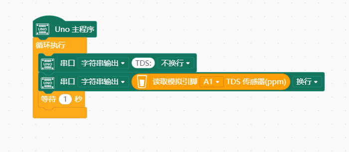
- “扩展”中选择“主控板”中的“Arduino Uno”。 "扩展"“传感器”中搜索选择“TDS传感器”。详细教程:Mind+基础wiki教程-加载扩展库流程
- 进行编程,程序如下图:
- 菜单“连接设备”,“上传到设备”
- 程序上传完毕后,打开串口即可看到数据输出。详细教程:Mind+基础wiki教程-串口打印
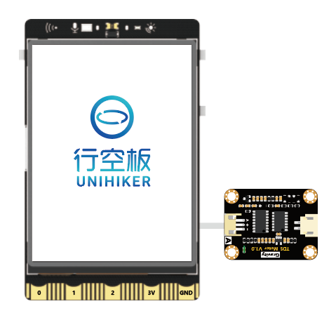
Mind+ Python模式编程(行空板)
Mind+Python模式为完整Python编程,因此需要能运行完整Python的主控板,此处以行空板为例说明
连接图
注意:
模拟TDS传感器支持的引脚有 0、1、2、3、4、10、21、22,积木块中标 “ A ” 的引脚
操作步骤
1、下载及安装官网最新软件。下载地址:https://www.mindplus.cc 详细教程:Mind+基础wiki教程-软件下载安装
2、切换到“Python模式”。“扩展”中选择“官方库”中的“行空板”和“pinpong库”中的”pinpong初始化“和“模拟TDS传感器”。切换模式和加载库的详细操作链接
3、进行编程
4、连接行空板,程序点击运行后,可在终端查看数据。行空板官方文档-行空板快速上手教程 (unihiker.com)
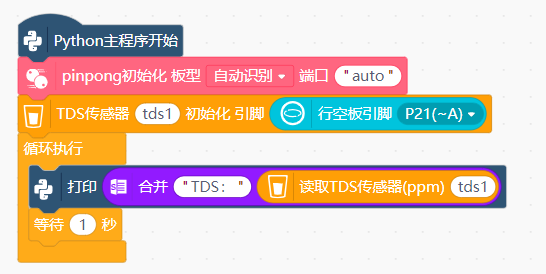
代码编程
以pinpong库为例,行空板官方文档-行空板快速上手教程 (unihiker.com)
#  -*- coding: UTF-8 -*-

# MindPlus
# Python
from pinpong.libs.dfrobot_tds import TDS
from pinpong.extension.unihiker import *
from pinpong.board import Board,Pin
from pinpong.board import Board
from pinpong.board import Pin


Board().begin()
tds1 = TDS(Pin((Pin.P21)))

while True:
    print((str("TDS:") + str(tds1.get_value())))
常见问题
问:该传感器有温度补偿功能吗? 怎么进行温度补偿?
答:TDS探头不带温度补偿,但样例代码中预留了温度补偿算法,没有温度传感器时,temperature变量默认25℃。您可以外接一款防水的温度传感器,将温度传感器数值更新temperature变量,即可进行自动温度补偿。
更多问题及有趣的应用,可以 访问论坛 进行查阅或发帖。
