概述
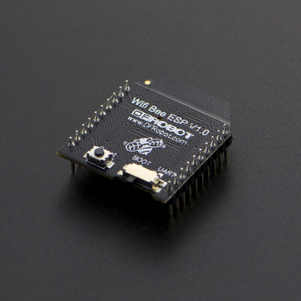
Wifi Bee-ESP8266 是采用XBEE造型设计的串口转WIFI解决方案的模块,体积尺寸紧凑,兼容XBEE的扩展底座,适用于各种3.3V的单片机系统。可用于扩展Arduino, 实现无线数据传输,远程控制。板载开关可用于方便地选择启动模块或者升级固件。
ESP8266 拥有强大的片上处理和存储能力,内置32位处理器,内置Lwip协议栈。支持AP+STA模式共存,可通过AT指令配置各种参数
性能描述
- Wi-Fi Direct (P2P)、soft-AP
- 内置 TCP/IP 协议栈
- 内置低功率 32 位 CPU:可以兼作应用处理器
- 支持 WPA WPA2/WPA2–PSK加密
- 支持UART接口
- 支持TTL串口到无线的应用
- 工作电压:3.3V,功耗<240Ma
- 无线标准:IEEE802.11b/g/n
- 频率: 2.4 GHz
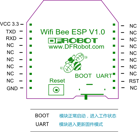
引脚分配图
教程
材料准备
STEP 1: 所需硬件
- 1xDFRduino UNO R3
- 1xIO传感器扩展板V7.1
- 1xFTDI Basic下载器
- 1xUSB 电缆方口
- 1xUSB mini
STEP 2: 所需软件
连接AP
STEP 3:准备工作
- 把ESP8266库放在Arduino安装目录下的libraries目录下面。
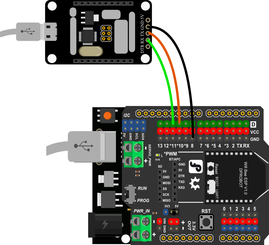
- IO扩展板插到UNO上,ESP8266插在IO扩展板上。
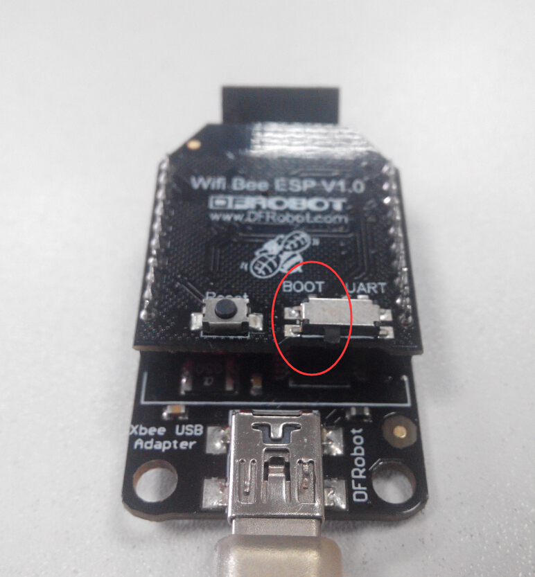
- 把IO/扩展板“RUN/Prog”开关拨在“Prog”,ESP8266模块“BOOT/UART”开关拨在"BOOT"上。
- 要查看调试信息,FTDI的TXD接IO扩展板的10脚,RXD接IO扩展板的11脚,GND接到扩展板的GND脚。
- 给UNO下载一个简单的Led闪烁的代码,然后把"RUN/Prog"拨到"RUN".(Arduino IDE--File--Examples--Basics--Blink)。
- 打开串口调试软件CoolTerm。


STEP 4:第一个实验,连接一个AP
- 打开CoolTerm,点击“Connect”。
- 把IO扩展板的“RUN/Prog”开关拨在“Prog”。
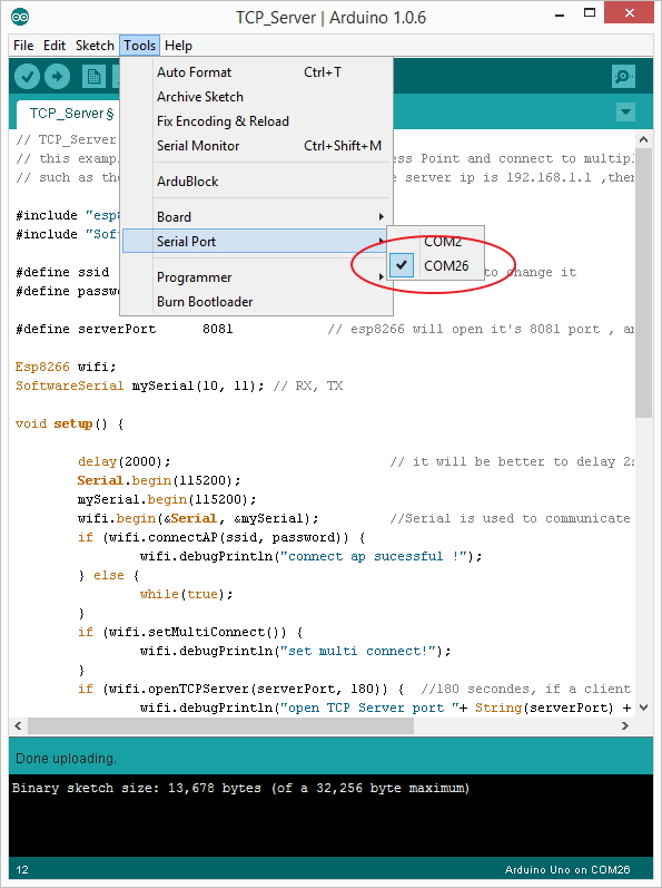
- 打开Arduino IDE,第一个例子,File--Example--ESP8266--ConnectAP,根据实际更改ssid和password。

- 下载程序完成后把“RUN/Prog”开关拨在“RUN”。
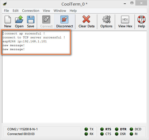
- 观察CoolTerm输出的信息,出现 "connected AP"表示模块已经连接上AP了。

STA模式,连接单个TCP服务器
STEP 5:第二个实验,ESP8266工作在STA模式,作为TCP客户端,连接单个TCP服务器
-
把IO扩展板的“RUN/Prog”开关拨在“Prog"。
-
把连接UNO的数据线断开,重新连接。
-
打开第二个例子,File--Example--ESP8266--TCP_Client_Single,根据实际更改ssid, password ,服务器IP地址,端口。

-
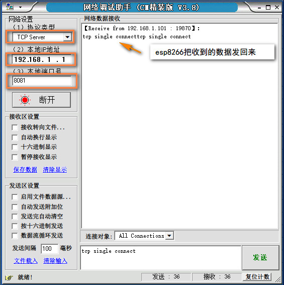
打开网络调试助手,协议类型选择TCP Server, 本地IP地址和本地端口号为上面代码中的设定值,默认为192.168.1.1和8081,点击连接。打开CoolTerm,连接串口。
-
下载程序到UNO后,把“RUN/Prog”开关拨在“RUN”。
-
观察CoolTerm 会提示是否成功连接到服务器,连接成功后,在网络调试助手中发送一段信息"tcp single connect",在连接框中会收到这个信息,这是ESP8266收到消息后把内容再转发回来。你可以修改这部分代码,对数据进行不同的处理
STA模式,连接多个TCP服务器
STEP 6:第三个实验,ESP8266工作在STA模式,作为客户端,连接多个TCP服务器
-
把IO扩展板的“RUN/Prog”开关拨在“Prog。
-
把连接UNO的数据线断开,重新连接。
-
打开第三个例子,File--Example--ESP8266--TCP_Client_Multi, 根据实际更改ssid, password ,服务器IP地址,端口

-
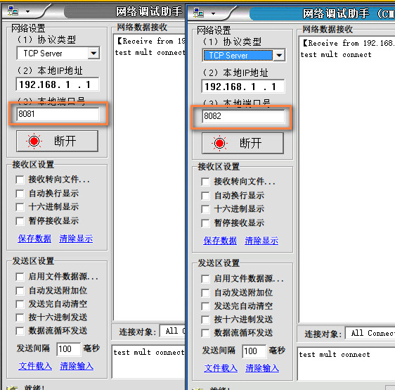
打开2个网络调试助手,协议类型选择TCP Server, 默认情况下本地IP地址都为192.168.1.1,本地端口号为8081和8082,点击连接。打开CoolTerm,连接串口。
-
下载程序后,把"RUN/Prog"开关拨在"RUN"。
-
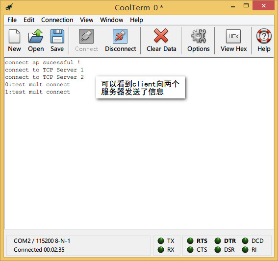
观察CoolTerm,会提示当前是否连接到两个服务器。2个网络调试助手作为TCP的服务器,在发送框中发送数据"test mult connect",ESP8266会给每个服务器发回这个消息。ESP8266最多可以连接5个服务器。
STA模式,作为客户端进行数据透传
STEP 7:第四个实验,ESP8266工作在STA模式,作为TCP客户端,进行数据透传
-
把IO扩展板的“RUN/Prog”开关拨在“Prog。
-
把连接UNO的数据线断开,重新连接。
-
打开第四个例子,File--Example--ESP8266--TCP_Pure_Data_Mode, 根据实际更改ssid, password ,服务器IP地址和端口。

-
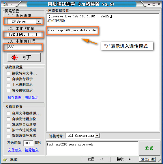
打开网络调试助手,协议类型选择TCP Server, 本地IP地址和本地端口号为上面代码中的设定值,默认为192.168.1.1和8081,点击连接打开CoolTerm,连接串口。
-
下载程序完成后,把"RUN/Prog"开关拨在"RUN"。
-
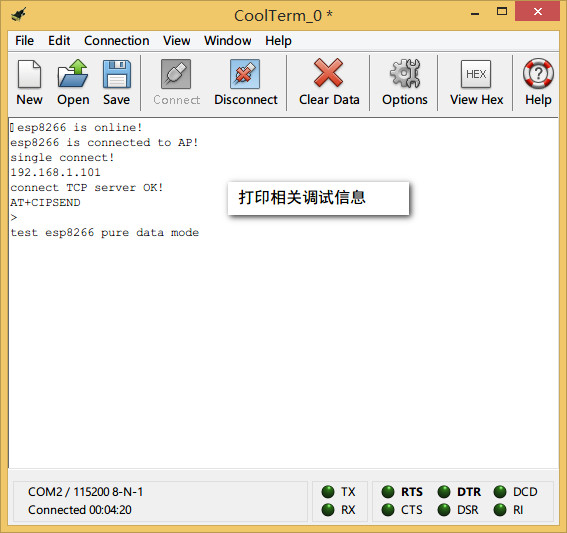
观察CoolTerm,会提示是否成功连接服务器,如果不成功,则给模块重新上电。当打印出">"符号时,表示模块进入了透传模式,在透传模式,数据传输速率会比普通发送模式快。在网络调试助手的发送框中发送"test esp8266 pure data mode"在接收框中会收到这条信息,这是因为ESP8266把收到的信息又转发回了服务器,你可以在代码中修改这一部分的内容。
STA模式,作为服务器
STEP 8:第四个实验,ESP8266工作在STA模式,作为TCP服务器
注意:目前,ESP8266的服务器状态并不稳定,我们正在努力解决。不过我们向您提供了server模式样例代码,以及用户手册,您可以尝试建立服务器。
更新固件
STEP 9:更新固件
请参考帖子: https://mc.dfrobot.com.cn/thread-276057-1-1.html
应用-远程控制一个LED灯
这个应用是建立在第二个应用基础之上,假如您做过了第二个实验,您可以在13脚上加一个LED灯(板子上13脚已经连接了一个LED),然后再上传下面的程序,模块和电脑建立连接之后,从电脑发送“H”开灯,发送“L”关灯。
// this example use esp8266 to connect to an Access Point and connect to SINGLE TCP Server which is at the same subnet
// such as the esp8266 is is 192.168.1.3, and the server ip is 192.168.1.1 ,then esp8266 can connect to the server

//Then connect a LED on Digital pin13, and open the software on PC_TCP server, send command to control the LED state:
//send "H" to turn ON LED; send "L" to turn OFF LED

#include "esp8266.h"
#include "SoftwareSerial.h"

#define ssid        "test"      // you need to change it
#define password    "12345678"

#define serverIP    "192.168.1.1"
#define serverPort  "8081"
int ledPin = 13;
String incomingData = "";

Esp8266 wifi;
SoftwareSerial mySerial(10, 11); // RX, TX

void setup() {
  pinMode(ledPin, OUTPUT);
  delay(2000);              // it will be better to delay 2s to wait esp8266 module OK
  Serial.begin(115200);
  mySerial.begin(115200);
  wifi.begin(&Serial, &mySerial);       //Serial is used to communicate with esp8266 module, mySerial is used to debug
  if (wifi.connectAP(ssid, password)) {
    wifi.debugPrintln("connect ap sucessful !");
  } else {
    while (true);
  }
  wifi.setSingleConnect();
  if (wifi.connectTCPServer(serverIP, serverPort)) {
    wifi.debugPrintln("connect to TCP server successful !");
  }
  String ip_addr;
  ip_addr = wifi.getIP();
  wifi.debugPrintln("esp8266 ip:" + ip_addr);
}

void loop() {
  int state = wifi.getState();
  switch (state) {
    case WIFI_NEW_MESSAGE:
      wifi.debugPrintln("new message!");
      incomingData = wifi.getMessage();
      wifi.sendMessage(incomingData);       //send the message to TCP server what it has received
      wifi.setState(WIFI_IDLE);
      break;
    case WIFI_CLOSED :                          //reconnet to the TCP server
      wifi.debugPrintln("server is closed! and trying to reconnect it!");
      if (wifi.connectTCPServer(serverIP, serverPort)) {
        wifi.debugPrintln("reconnect OK!");
        wifi.setState(WIFI_IDLE);
      }
      else {
        wifi.debugPrintln("reconnect fail");
        wifi.setState(WIFI_CLOSED);
      }
      break;
    case WIFI_IDLE :
      int sta = wifi.checkMessage();
      wifi.setState(sta);
      break;
  }
  if (incomingData == "H")  {
    digitalWrite(13, HIGH);
    incomingData = "";
  }
  else if (incomingData == "L")  {
    digitalWrite(13, LOW);
    incomingData = "";
  }
}

AT指令
新购买模块,可能需要先进行AT指令配置,方可使用。
AT指令使用方法
-
将WIFI BEE 插在FTDI USB 转串口上,选择开关拨在“BOOT”一边。
-
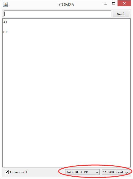
使用串口助手,比如Arduino自带的IDE 监视窗口。选择“Both NL & CR”,“115200”。
-
发送AT,就可以进入AT指令配置了。

具体的AT命令表可参考 ESP8266芯片手册