Bluno M3 硬件外设
GPIO
概述
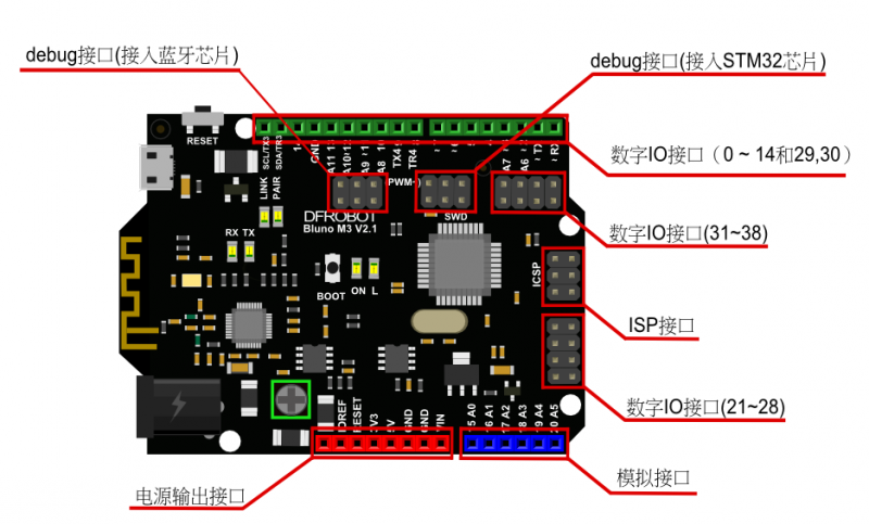
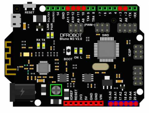
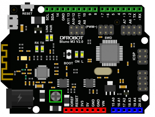
Bluno M3是非常容易使用通用输入/输出数字IO口,兼容Arduino的IO操作方式。但是拥有更多可操作的数字IO口,GPIO端口是从数字0到38。
GPIO 参考函数
I/O输入输出函数完全兼容Arduino uno控制方式。
函数接口:
pinMode(pin, mode);
digitalRead(pin);
digitalWrite(pin,value);
参考例程
    int led = 13;  // Pin 13 has an LED connected on most Arduino boards.

    void setup() {
      pinMode(led, OUTPUT);   // initialize the digital pin as an output.
    }

    void loop() {
      digitalWrite(led, HIGH);   // turn the LED on (HIGH is the voltage level)
      delay(1000);               // wait for a second
      digitalWrite(led, LOW);    // turn the LED off by making the voltage LOW
      delay(1000);               // wait for a second
    }
USART
概述
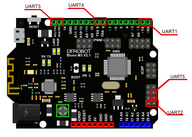
USART 是用来进行串口通信的,Bluno M3共有5个串口Serial1(TX1,RX1)、Serial2(TX2, RX2)、Serial3(TX3, RX3)、Serial4(TX4, RX4)、Serial5(TX5, RX5)。Bluno M3的TX链接其他串口设备的RX,它的RX链接其他设备的TX.uart1和usb调试口共有一个硬件口。
使用UART1时,调用Serial函数即可,完全兼容Arduino函数库。
USART 参考函数
支持Arduino基本串口库函数,参考Arduino官网:入口
实验连线:
把Rx1与Rx2直接用杜邦线连接。
参考例程
void setup() {
  // initialize both serial ports:
  Serial1.begin(9600);
  Serial2.begin(9600);
}

void loop() {
  // read from port 2, send to port 1:
  if (Serial2.available()) {
    Serial1.println("Serial2");
  }

  // read from port 1, send to port 2:
  if (Serial1.available()) {
    Serial1.println("Serial1");
  }
}
PWM
概述
PWM是该模块的基础功能,Bluno M3板子上标有“~”的端口都是PWM口(0, 1, 2, 3, 6, 7, 11, 12 , 21, 22,27, 28, 35, 36, 37, 38)。每个管脚都与内部的定时器各通道相连接,PWM模块已经把硬件封装好了,
在使用的过程中用户不需要关心内部定时器配置等情况。
Bluno M3支持两种方式对PWM模块进行操作:
方式一:
直接调用void analogWrite(uint32_t ulPin,uint32_t ulValue)该函数默认输出周期固定为1KHz、占空比由ulValue的值改变的PWM方波到ulPin指定的具有PWM功能的管脚,且PWM的分辨率为8位。这种方式限制了PWM的输出能力。
方式二:
1、先调用**void pwmMode(uint32_tulPin,uint32_t pwmFre,uint32_t pwmMode)该函数配置指定输出PWM方波的管脚,pwm方波的频率和模式,其中模式有8位和12位之分,分别由PWM_8_BIT和PWM_12_BIT指定。
在PWM_8_BIT模式下,pwmFre的取值范围为: 4Hz < pwmFre < 281250Hz 在PWM_12_BIT模式下,pwmFre的取值范围为: 1Hz < pwmFre < 17578Hz.
2、调用void pwmWrite(uint32_t ulPin, uint32_t ulValue) **该函数给指定管脚ulPin输出一个值ulValue决定的占空比的PWM方波,占空比计算公式如下:
在MODE_8_BIT下ulValue的取值范围是:0 ~ 255,Dutycycle = ulValue / 255 *100%
在MODE_12_BIT下ulValue的取值范围是:0 ~ 4095,Dutycycle = ulValue / 4095*100%
PWM 参考函数
void analogWrite(uint32_t ulPin, uint32_t ulValue)
函数功能: 输出一个占空比由ulValue决定且频率为1KHz的PWM方波。
参数说明:
ulPin:具有PWM功能的端口编号。例如指定D7端口输出PWM波形,则ulPin 传入7即口;
ulValue: 比较输出值,它决定了该方波的占空比,计算公式: 占空比 = (ulValue / 255 )*100%,传值为0~255;
返回值:无。
void pwmMode( uint32_t ulPin, uint32_t pwmFre, uint32_t pwmMode)
函数功能:配置PWM的波形出去端口,PWM的频率以及PWM的模式。
参数说明:
ulPin:具有PWM功能的端口编号。例如指定D7端口输出PWM波形,则ulPin 传入7即口;
pwmFre:PWM的频率,其传值范围有pwmMode决定;
pwmMode:指定该PWM的分辨率,其值为MODE_8_BIT或者MODE_12_BIT;
返回值:无。
参考例程
    第一种方式示例代码:

      int pwmPin = 0;    // pwm connected to digital pin 0
      void setup() {
         //nothing happens in setup
     }

      void loop() {

        // fade in from min to max in increments of 5 points:
        for (int fadeValue = 0 ; fadeValue <= 255; fadeValue += 5) {

            analogWrite(pwmPin, fadeValue);         // sets the value (range from 0 to 255):
            delay(30);          // wait for 30 milliseconds to see the dimming effect
        }

        // fade out from max to min in increments of 5 points:
        for (int fadeValue = 255 ; fadeValue >= 0; fadeValue -= 5) {
            analogWrite(pwmPin, fadeValue);           // sets the value (range from 0 to 255):
            delay(30);                              // wait for 30 milliseconds to see the dimming effect
        }
     }

    第二种方式示例代码:

    #include <Arduino.h>
     int pwmPin = 0;    // PWM connected to digital pin 0
     int flag = 1;
     void setup() {
         //initailizing the pwmPin,  setting the period of PWM as 2000Hz and it's mode as 8'bit.
         pwmMode(pwmPin, 2000, PWM_8_BIT);
     }

     void loop() {

         // output the duty of the PWM , one is 39% based on the formula privided above.
         pwmWrite(pwmPin, 100);
         while (1);

    }
ADC
概述
ADC模块可以将输入的模拟信号转化成数字信号,电压区间是0-3.3V,Bluno M3上共有模拟端口12个分别为(A0,A1,A2,A3,A4,A5,A6,A7,A8,A9,A10,A11)。Bluno M3有两种方式对ADC模块进行操作:
方式一:
直接调用 analogRead(uint32_t ulPin),默认10位分辨率采样。单次不循环采样,要实现循环采样必须在应用程序中循环调用analogRead();使用方式与Uno类似。
方式二:
1、先调用函数**void adcMode(uint32_t ulPin, uint8_t Mode)**设置指定的adc管脚的工作模式。模式有三种:ADC_8_BIT ,ADC_10_BIT ,ADC_12_BIT 。
- ADC_8_BIT:把adc转换的结果映射在0~255范围内。
- ADC_10_BIT:把adc转换的结果映射在0~1023范围内。
- ADC_12_BIT:把adc转换的结果映射在0~4096范围内。
2、调用函数uint32_t adcRead(uint32_t ulPin)该函数将ulPin指定的模拟输入脚中的电压值转换成与Mode指定的分辨率相对应的数值,然后将其返回。比如模拟电压1.5V在ADC_8_BIT模式下,转换后得到116, 而在ADC_10_BIT下为465,在ADC_12_BIT模式下为1861。
ADC 参考函数
uint32_t analogRead(uint32_t ulPin)
函数功能:返回ulPin指定的adc转换后的结果。
参数说明:
** ulPin**: 具有ADC功能的管脚即标有字母A的管脚。比如要读入A0管脚的模拟输入值那么传入A0或者0即可,A0是定义的宏。
返回值:adc的转换结果。
void adcMode(uint32_t ulPin, uint8_t Mode)
函数功能:设置ulPin指定的adc管脚的工作模式。
参数说明
** ulPin**:具有ADC功能的管脚即标有字母A的管脚。比如要读入A0管脚的模拟输入值那么传入A0或者0即可,A0是定义的宏。
Mode:指定输出的数据格式。Mode可以为ADC_8_BIT,ADC_10_BIT ,ADC_12_BIT 。
返回值:无
**uint32_t adcRead(uint32_t ulPin) **
函数功能:返回一个由Mode指定的分辨率的数据数说明
ulPin: adcMod 中的端口编号一致。
返回值:adc的转换结果。
参考例程
第一种方式示例代码:
 int sensorPin = 0;    // select the input pin for the potentiometer
 int sensorValue = 0;  // variable to store the value coming from the sensor
 void setup() {

   Serial1.begin(9600);

 }

 void loop() {

   sensorValue = analogRead(sensorPin);
   Serial1.println((int)sensorValue);
   delay(1000);

 }


第二种方式示例代码:

 int sensorPin = 0;    // select the input pin for the potentiometer
 int sensorValue = 0;  // variable to store the value coming from the sensor

 void setup() {
    Serial1.begin(9600);
    adcMode(sensorPin, ADC_12_BIT);
 }

 void loop() {

    sensorValue = adcRead(sensorPin);
    Serial1.println((int)sensorValue);
    delay(1000);
}
External Interrupts
概述
外部中断能够用来检测端口电平的改变,当检测到电平变化时,则调用注册的回调函数,执行相应功能。0-38都可以作为外部中断管脚。
参考函数
*void attachInterrupt(uint32_t pin, void (callback)(void), uint32_t mode)
函数功能:配置一个指定的管脚为外部中断,并为该中断注册一个回调函数。
参数说明:
pin:0 ~ 38引脚编号。
callback:回调函数。
mode: 可以指定为 CHANGE, RISING, FALLING中的其中一种。其中CHANGE指的是上升沿下降沿均被触发,RISING指的是上升沿触发FALLING指的是下降沿触发。
返回值:无。
参考例程
    char intNumber = 2;

    void setup() {
      Serial1.begin(9600);
      attachInterrupt(intNumber, warning, CHANGE);
    }

    void loop() {
    }

    void warning(){
      Serial1.println((int)intNumber);
    }
I2C
概述
I2C总线是由PHILIPS公司开发的两线式总线,是一种串行外设总线接口,用于连接微控制器及其外围设备,是微电子通信控制领域广泛采用的一种总线标准。它是同步通信的一种特殊形式,具有接口线少,控制方式简单,器件封装形式小,通信速率较高等优点。I2C 总线支持任何IC 生产过程(CMOS、双极性)。通过串行数据(SDA)线和串行时钟(SCL)线在连接到总线的器件间传递信息。每个器件都有一个唯一的器件地址(无论是微控制器——MCU、LCD 驱动器、存储器或键盘接口),而且都可以作为一个发送器或接收器(由器件的功能决定)。LCD 驱动器只能作为接收器,而存储器则既可以接收又可以发送数据。除了发送器和接收器外,器件在执行数据传输时也可以被看作是主机或从机。主机是初始化总线并产生时钟信号的器件。此时,任何被寻址的器件都被认为是从机。Bluno M3提供两个硬件I2C端口,分别是I2C1和I2C2,但由于采用软件模拟I2C灵活高,易实现,仅需要任意两个通用I0口即可,所以现在我们的板子只提供软件模拟的I2C接口,将来的版本可能会兼容硬件I2C。Bluno M3为了兼容UNO,Wire类的对象在调用 Wire.begin()时,默认配置了板子上的SDA,SCL这两个端口作为模拟I2C接口。
参考函数
void begin()
函数功能:该函数默认初始化板子上SDL,SCL管脚为I2C接口;
参数说明:
无参数。
返回值:无
void begin(uint8_t,uint8_t)
函数功能:指定任何两个通用IO口分别为I2C的SDA,SCL。
sda:为模拟的SDA管脚,其值为0-38;
scl:为模拟的SCL管脚,其值为0-38;
返回值:无。
void eginTransmission(uint8_t slave_address)
函数说明:发送从机的地址。
参数说明:
slave_address: 为从机的地址。
返回值:无
uint8_t requestFrom(uint8_t slave_address, int length)
函数说明:接收从机发送来的数据;
参数说明:
slave_address:从机的地址。
length: 接收数据的长度,单位:字节。
返回值:实际接收到的长度。
void write(uint8_t value)
函数说明:发送数据到从机;
参数说明:
value: 发送的数据。
返回值:无。
uint8_t endTransmission(void)
函数说明:发送start信号(启始信号),发送buffer里的数据到I2C总线上,最后发送stop信号(结束信号,释放总线)。
参数说明:
无参数。
返回值:若返回0,表示数据发送成功;若为非零,则表示为发送失败。
** uint8_t available(void)**
函数说明:查询是否还有数据可读。
参数说明:
无参数。
返回值:返回此时接受buffer中剩余待读取的数据长度,单位:字节
uint8_t read(void)
函数说明:读取I2C接受到的数据,一次读取一个字节。
参数说明:
无参数。
返回值:返回读取到的数据。
参考例程
    /*
      *  Use the I2C bus with EEPROM 24C256
      *
      */

    #include <Wire.h> //I2C library
    #define EEPROM_ADDR 0x50           // I2C Buss address of 24LC256 256K EEPROM
    #define PAGESIZE    64             // 64 bytes each Page of 24LC256
    int temp ;
    void setup()
    {
      Wire.begin();   // join I2C bus (address optional for master)
      Serial1.begin(9600);
    }

    void loop()
    {
             int i;
             byte arr[64];
             byte arread[64];
             // TESTS FOR EACH FUNCTION BEGIN HERE
              Serial1.println("the data is going to be write to the 24LC256:");
             for (i = 0; i < PAGESIZE; i++)
             {
                 arr[i] = i;
                 Serial1.print(i);
                 Serial1.print(' ');
                 if (i != 0 && i % 10 == 0)
                    Serial1.println("");
             }

              Serial1.println("");
             i2c_eeprom_write_page(EEPROM_ADDR, 0, arr, PAGESIZE);
             delay(100);

             i2c_eeprom_read_buffer(EEPROM_ADDR, 0, arread,PAGESIZE);
             Serial1.println("the data is reading from the 24LC256  :");
             delay(1000);

             for (i = 0; i < PAGESIZE; i++)
             {
                 Serial1.print(arread[i]);
                 Serial1.print(' ');
                 if (i != 0 &&i % 10 == 0)
                     Serial1.println("");

             }
              Serial1.println("");
             if (memcmp(arr, arread, PAGESIZE) == 0)
             {
                 Serial1.println("the driver of the 24LC256 correct!");
             }
             else
             {
                  Serial1.println("the driver of the 24LC256 fault!");
             }

             while (1);
      }

    void i2c_eeprom_write_byte( int deviceaddress, unsigned int eeaddress, byte data ) {
        int rdata = data;
        Wire.beginTransmission(deviceaddress);
        Wire.write((int)(eeaddress >> 8)); // MSB
        Wire.write((int)(eeaddress & 0xFF)); // LSB
        Wire.write(rdata);
        Wire.endTransmission();
      }

      // WARNING: address is a page address, 6-bit end will wrap around
      // also, data can be maximum of about 30 bytes, because the Wire library has a buffer of 32 bytes
    void i2c_eeprom_write_page( int deviceaddress, unsigned int eeaddresspage, byte* data, byte length ) {
        Wire.beginTransmission(deviceaddress);
        Wire.write((int)(eeaddresspage >> 8)); // MSB
        Wire.write((int)(eeaddresspage & 0xFF)); // LSB
        byte c;
        for ( c = 0; c < length; c++)
          Wire.write(data[c]);
        Wire.endTransmission();
      }

    byte i2c_eeprom_read_byte( int deviceaddress, unsigned int eeaddress ) {
        byte rdata = 0xFF;
        Wire.beginTransmission(deviceaddress);
        Wire.write((int)(eeaddress >> 8)); // MSB
        Wire.write((int)(eeaddress & 0xFF)); // LSB
        Wire.endTransmission();
        Wire.requestFrom(deviceaddress,1);
        if (Wire.available()) rdata = Wire.read();
        return rdata;
      }

      // maybe let's not read more than 30 or 32 bytes at a time!
    void i2c_eeprom_read_buffer( int deviceaddress, unsigned int eeaddress, byte *buffer, int length ) {
        Wire.beginTransmission(deviceaddress);
        Wire.write((int)(eeaddress >> 8)); // MSB
        Wire.write((int)(eeaddress & 0xFF)); // LSB
        Wire.endTransmission();
        Wire.requestFrom(deviceaddress,length);
        int c = 0;
        for ( c = 0; c < length; c++ )
          if (Wire.available()) buffer[c] = Wire.read();
      }
SPI
概述
SPI是一种高速、全双工和同步的通信总线。Bluno M3 提供两个SPI接口,分别是SPI1和SPI2。
参考函数
参考Arduino官方库函数:入口
注:SPI1对应的是SPI.begin(),SPI2对应的是SPI_2.begin().
参考例程
    #include "SPI.h"


    #define SD_TYPE_ERR     0X00
    #define SD_TYPE_MMC     0X01
    #define SD_TYPE_V1      0X02
    #define SD_TYPE_V2      0X04
    #define SD_TYPE_V2HC    0X06

    #define CMD0    0
    #define CMD1    1
    #define CMD8    8
    #define CMD9    9
    #define CMD10   10
    #define CMD12   12
    #define CMD16   16
    #define CMD17   17
    #define CMD18   18
    #define CMD23   23
    #define CMD24   24
    #define CMD25   25
    #define CMD41   41
    #define CMD55   55
    #define CMD58   58
    #define CMD59   59
    #define MSD_DATA_OK                0x05
    #define MSD_DATA_CRC_ERROR         0x0B
    #define MSD_DATA_WRITE_ERROR       0x0D
    #define MSD_DATA_OTHER_ERROR       0xFF
    //SD¿¨»ØÓ¦±ê¼Ç×Ö
    #define MSD_RESPONSE_NO_ERROR      0x00
    #define MSD_IN_IDLE_STATE          0x01
    #define MSD_ERASE_RESET            0x02
    #define MSD_ILLEGAL_COMMAND        0x04
    #define MSD_COM_CRC_ERROR          0x08
    #define MSD_ERASE_SEQUENCE_ERROR   0x10
    #define MSD_ADDRESS_ERROR          0x20
    #define MSD_PARAMETER_ERROR        0x40
    #define MSD_RESPONSE_FAILURE       0xFF


    const int slaveSelectPin = 4;
    u8  SD_Type=0;

    u8 SD_WaitReady(void)
    {
      u32 t=0;
      do
      {
        if(SPI.transfer(0xff)==0xff)
        {
          return 0;//is ok!!!
        }
        t++;
      }while(t<0xffffff);
      return 1;
    }

    void SD_DisSelect(void)
    {
        digitalWrite(slaveSelectPin, HIGH);
        SPI.transfer(0xff);
    }

    u8 SD_Select(void)
    {
        digitalWrite(slaveSelectPin, LOW);
        if(SD_WaitReady()==0)
              return 0;
        SD_DisSelect();
        return 1;
    }

    u8 SD_SendCmd(u8 cmd, u32 arg, u8 crc)
    {
        u8 r1;
        u8 Retry=0;
        SD_DisSelect();
        if(SD_Select())
        {
          return 0XFF;
        }
        SPI.transfer(cmd | 0x40);//·Ö±ðдÈëÃüÁî
        SPI.transfer(arg >> 24);
        SPI.transfer(arg >> 16);
        SPI.transfer(arg >> 8);
        SPI.transfer(arg);
        SPI.transfer(crc);
        if(cmd==CMD12)
          SPI.transfer(0xff);
        Retry=0X1F;
        do
        {
        r1=SPI.transfer(0xFF);
        }while((r1&0X80) && Retry--);

        return r1;
    }

    u8 SD_Initialize(void)
    {
        u16 retry;
        u8 r1;
        u8 buf[4];
        u16 i;
        // set the slaveSelectPin as an output:
        pinMode (slaveSelectPin, OUTPUT);
        // initialize SPI:
        SPI.begin();
            SPI.setClockDivider(SPI_CLOCK_DIV256);
            SPI.setDataMode(SPI_MODE3);
        //SPI.setDataMode(SPI_MODE3);
        SPI.setClockDivider(SPI_CLOCK_DIV256);
        for(int i=0;i<10;i++)
        SPI.transfer(0xff);
        retry=20;
        do
        {
            r1=SD_SendCmd(CMD0,0,0x95);
        }while((r1!=0x01)&&retry--);
        SD_Type=0;
        if(r1==0X01)
        {
            if(SD_SendCmd(CMD8,0x1AA,0x87)==1)//SD V2.0
            {
                for(int i=0;i<4;i++)buf[i]=SPI.transfer(0XFF);
                if(buf[2]==0X01&&buf[3]==0XAA)
                {
                    retry=0XFFFE;
                    do
                    {
                        SD_SendCmd(CMD55,0,0X01);
                        r1=SD_SendCmd(CMD41,0x40000000,0X01);
                    }while(r1&&retry--);
                    if(retry&&SD_SendCmd(CMD58,0,0X01)==0)
                    {
                        for(int i=0;i<4;i++)buf[i]=SPI.transfer(0XFF);
                        if(buf[0]&0x40)SD_Type=SD_TYPE_V2HC;
                        else SD_Type=SD_TYPE_V2;
                    }
                }
            }else//SD V1.x/ MMC V3
            {
                SD_SendCmd(CMD55,0,0X01);
                r1=SD_SendCmd(CMD41,0,0X01);
                if(r1<=1)
                {
                    SD_Type=SD_TYPE_V1;
                    retry=0XFFFE;
                    do
                    {
                        SD_SendCmd(CMD55,0,0X01);
                        r1=SD_SendCmd(CMD41,0,0X01);
                    }while(r1&&retry--);
                }else
                {
                    SD_Type=SD_TYPE_MMC;//MMC V3
                    retry=0XFFFE;
                    do
                    {
                        r1=SD_SendCmd(CMD1,0,0X01);
                    }while(r1&&retry--);
                }
                if(retry==0||SD_SendCmd(CMD16,512,0X01)!=0)SD_Type=SD_TYPE_ERR;
            }
        }
        SD_DisSelect();
        //SPIsetClockDivider(SPI_BaudRatePrescaler_2);
        if(SD_Type)
        return 0;
        else if(r1)return r1;
        return 0xaa;
    }

    u8 SD_GetResponse(u8 Response)
    {
        u16 Count=0xFFF;
        while ((SPI.transfer(0XFF)!=Response)&&Count)Count--;
        if (Count==0)return MSD_RESPONSE_FAILURE;
        else return MSD_RESPONSE_NO_ERROR;
    }

    u8 SD_RecvData(u8*buf,u16 len)
    {
        if(SD_GetResponse(0xFE))return 1;
        while(len--)
        {
            *buf=SPI.transfer(0xFF);
            buf++;
        }

        SPI.transfer(0xFF);
        SPI.transfer(0xFF);
        return 0;
    }

    u8 SD_GetCSD(u8 *csd_data)
    {
        u8 r1;
        r1=SD_SendCmd(CMD9,0,0x01);
        if(r1==0)
        {
          r1=SD_RecvData(csd_data, 16);
        }
      SD_DisSelect();
      if(r1)
        return 1;
      else
        return 0;
    }

    u32 SD_GetSectorCount(void)
    {
        u8 csd[16];
        u32 Capacity;
        u8 n;
        u16 csize;
        if(SD_GetCSD(csd)!=0)
        {
          return 0;
        }

        if((csd[0]&0xC0)==0x40)
        {
            csize = csd[9] + ((u16)csd[8] << 8) + 1;
            Capacity = (u32)csize << 10;
        }
        else
        {
            n = (csd[5] & 15) + ((csd[10] & 128) >> 7) + ((csd[9] & 3) << 1) + 2;
            csize = (csd[8] >> 6) + ((u16)csd[7] << 2) + ((u16)(csd[6] & 3) << 10) + 1;
            Capacity= (u32)csize << (n - 9);
        }
        return Capacity;
    }

    u8 SD_ReadDisk(u8* buf,u32 sector,u8 cnt)
    {
        u8 r1;
        if(SD_Type!=SD_TYPE_V2HC)sector <<= 9;
        if(cnt==1)
        {
            r1=SD_SendCmd(CMD17,sector,0X01);
            if(r1==0)
            {
                r1=SD_RecvData(buf,512);
            }
        }else
        {
            r1=SD_SendCmd(CMD18,sector,0X01);
            do
            {
                r1=SD_RecvData(buf,512);
                buf+=512;
            }while(--cnt && r1==0);
            SD_SendCmd(CMD12,0,0X01);
        }
        SD_DisSelect();
        return r1;//
    }

    u8 SD_WriteDisk(u8* buf,u32 sector,u8 cnt)
    {
        u8 r1;
        if(SD_Type!=SD_TYPE_V2HC)sector *= 512;
        if(cnt==1)
        {
            r1=SD_SendCmd(CMD24,sector,0X01);
            if(r1==0)
            {
                r1=SD_SendBlock(buf,0xFE);
            }
        }
            else
        {
            if(SD_Type!=SD_TYPE_MMC)
            {
                SD_SendCmd(CMD55,0,0X01);
                SD_SendCmd(CMD23,cnt,0X01);
            }
            r1=SD_SendCmd(CMD25,sector,0X01);
            if(r1==0)
            {
                do
                {
                    r1=SD_SendBlock(buf,0xFC);
                    buf+=512;
                }while(--cnt && r1==0);
                r1=SD_SendBlock(0,0xFD);
            }
        }
        SD_DisSelect();
        return r1;//
    }

    u8 SD_SendBlock(u8*buf,u8 cmd)
    {
        u16 t;
        if(SD_WaitReady())return 1;
        SPI.transfer(cmd);
        if(cmd!=0XFD)
        {
            for(t=0;t<512;t++)
                  SPI.transfer(buf[t]);
              SPI.transfer(0xFF);
              SPI.transfer(0xFF);
            t=SPI.transfer(0xFF);
            if((t&0x1F)!=0x05)return 2;
        }
        return 0;
    }

    void setup()
    {
      u32 sector_size;
      u8 ybuf[512]="DFROBOT!";
      u8 xbuf[512];

      Serial1.begin(9600);
     // SPI.begin();
      Serial1.println("Serial1 init is OK!");
       while(SD_Initialize()!=0)
       {
         Serial1.println("SD init Failed");
         delay(1000);
       }
       Serial1.println("SD init OK!");
       sector_size=SD_GetSectorCount()/1024;
      // sector_size=0x3af000;
       Serial1.println(sector_size/4);
       SD_WriteDisk(ybuf,0,1);
       delay(500);
       SD_ReadDisk(xbuf,0,1);

       Serial1.println(xbuf[0]);
       Serial1.println(xbuf[1]);
       Serial1.println(xbuf[2]);
       Serial1.println(xbuf[3]);
       Serial1.println(xbuf[4]);
       Serial1.println(xbuf[5]);
    }

    void loop() {
      // put your main code here, to run repeatedly:

    }
Timer
概述
Bluno M3的软件库里实现了一个软件定时器,用于满足用户在某些特殊场合下的定时处理需求。该定时器被封装在Timer类中,用于只需要定义并初始化对象就可以方便使用。Timer支持单次定时中断处理退出模式和周期性定时中断处理模式,同一个定时器对象可以在两种模式之间切换。Timer类也支持回掉函数的更换。
参考函数
Timer(void)
函数功能:默认构造函数。
参数说明:
无参数。
返回值: 无。
Timer(uint32_t ms, Func tfunc, tKind_t type, void *data)
函数功能:支持实例化对象时传参。
参数说明:
ms:定时时间,单位:ms;
tfunc:注册的回调函数,函数的类型为void (**Func)(void **);
type:指定该定时器的类型,type可以是t_single或者t_period中的一种 ;t_single表示的是:该定时器定时时间一到调用完回调函数后就自动销毁了,即调用一次回调函数后就不能在用了;t_period表示:该定时器周期性的被中断,回调函数周期性的被调用,用户可以手动的调用该定时器的析构函数将其销毁。
data:回调函数需要处理的数据指针;
返回值: 无。
~Timer():
函数功能:析构函数,调用后定时器自动销毁。
参数说明:
无参数。
返回值: 无。
*void config(uint32_t ms, Func tfunc, tKind_t type, voi data)
函数说明:用于配置定时器对象的函数。
参数说明:
ms:定时时间,单位:ms;
tfunc:注册的回调函数,函数的类型为void (*Func)(void *);
type:指定该定时器的类型。type可以是t_single或者t_period中的一种;
data:回调函数需要处理的数据指针;
返回值: 无。
uint8_t get_tNum(void)
函数说明:返回当前定时器的序列号。
参数说明:
无参数。
返回值:当前定时器的序列号。该序列号是创建定时器时分配的。
uint32_t get_resTime(void)
函数说明:返回当前定时器的剩余时间,单位ms。
参数说明:
无参数。
返回值: 定时器倒计时值,即剩余时间。
void change_callbackFunc(Func tFunc)
函数说明:改变当前定时器的回调函数。
ttFunc:函数指针,或函数名。
返回值: 无。
void hange_type(tKind_t ttype)
函数说明:改变当前定时器的模式。
参数说明:
ttype: 可以是t_single或者t_period;
返回值: 无。
参考例程
#include "timerobj.h"
#include <stdlib.h>
unsigned char td;

/*define the objects of the Timer */
Timer timer1(1000, myfunc, t_period, NULL );
Timer timer2(3000, myfunc1, t_period, NULL );

void myfunc(void *data)
{
     Serial1.println("it is processing the first call back function! on timer1\n");
}

void myfunc1(void *data)
{
     static int i;
     i++;
     Serial1.println(i);
     Serial1.println("it is processing the second call back function! on timer2\n");

     if (i == 3)
     {
         Serial1.println("changing the callback function for the timer1\n");
         timer1.change_callbackFunc(myfunc2);  // changing the callback function for the object timer1
      }

}

void myfunc2(void *data)
{

      static int i;
      i++;
      Serial1.println(i);
      Serial1.println("myfunc2");
      if (i == 2)
      {
         Serial1.println("changing the kind of type for timer2\n");
         timer2.change_type(t_single);  // changing the mode for the timer2 from t_period to t_single.
      }
}

void setup() {

      Serial1.begin(9600);

}

void loop() {


}
Servo
概述
舵机是一种伺服电机,可以通过PWM波信号给定转角角度信息,转动致指定角度并能保持、承受一定的外力矩。Bluno M3的舵机用户使用接口与Uno是一致的。Bluno 中构造了Servo类,如果用户想使用一个舵机 那么就调用attach()函数并参入一个端口信息实例化一个对象,该对象可以调用servo类的接口函数去实现各种复杂的功能。一个舵机对用一个Servo对象,这样的封装使用户对舵机的操作更加变得容易,方便。
参考函数
uint8_t attach(int pin)
函数功能:把pin指定的端口用于驱动舵机,并返回该舵机在所有正在使用的舵机中的编号。
参数说明:
pin: 0~38中的任意一个端口号。
返回值:返回该舵机在所有正在使用的舵机中的编号。
void write(int value)
函数功能:给定舵机一个旋转的角度值。
参数说明:
value:指定舵机旋转的度数,例如:如果要使舵机旋转1度,那么就让value = 1;如果要使舵机旋转20°,那么就让value = 20即可。
返回值:无。
参考例程
    /* Sweep
     by BARRAGAN <http://barraganstudio.com>
     This example code is in the public domain.

     2015/4/29
     by cuitzcl
     http://arduino.cc/en/Tutorial/Sweep
    */

    #include <ServoM3.h>

    Servo myservo;  // create servo object to control a servo
                    // twelve servo objects can be created on most boards

    int pos = 0;    // variable to store the servo position

    void setup()
    {
      myservo.attach(9);  // attaches the servo on pin 9 to the servo object
    }

    void loop()
    {
      for(pos = 0; pos <= 180; pos += 1) // goes from 0 degrees to 180 degrees
      {                                  // in steps of 1 degree
        myservo.write(pos);              // tell servo to go to position in variable 'pos'
        delay(15);                       // waits 15ms for the servo to reach the position
      }
      for(pos = 180; pos>=0; pos-=1)     // goes from 180 degrees to 0 degrees
      {
        myservo.write(pos);              // tell servo to go to position in variable 'pos'
        delay(15);                       // waits 15ms for the servo to reach the position
      }
    }
Flash
概述
Bluno M3采用的是stm32f103的ARM处理器,内部自带了一个容量为512K的flsh,在它上面可以存储并运行程序,也可以存储用户数据。flash共256个page,每个page大小为2KByte。一般地,在对flash写之前必须要先进行擦除操作,一次最多只能写一个page大小。如果用户直接对flash底层进行操作的话,难度大,不容易实现,并且严重影响用户设计的嵌入式系统的稳定性。为此Bulno M3在软件库里实现一个专门的Flash类,该封装了stm32f103芯片中的内部flash。它将flash分为两大区域:代码区和用户数据区。代码区是程序存储运行的地方,对用户来说是不可见的,地址范围0x08000000 ~ 0x08004FFF;而用户数据区可以被用户擦除,读写等,地址范围:0x08005000~0x08080000;这样用户可以不需要外接存储芯片的情况下也有492K可用于存储数据。Flash类使用起来非常方便,用户在写数据时可以不用考虑该区域flash是否已擦除。因为 Write函数自带擦除功能;用户也不需要考虑flash换页问题,因为Write函数实现了自动换页功能,使存储的数据在flash内部分布紧凑,大大提高了flash的利用率。
参考函数
FLASH_Status ErasePage(uint32_t Page_Address)
函数功能:擦除一个page。
参数说明:
Page_Address: page的首地址。 计算公式:Page_Address = 0x08005000 + i * 2048; i指的是page的编号,i = (0,1,2,...,246)。
返回值:如果擦除成功则返回FLASH_COMPLETE,即十进制4。FLASH_Status的定义如下: typedef enum{ FLASH_BUSY = 1,FLASH_ERROR_PG,FLASH_ERROR_WRP, FLASH_COMPLETE, FLASH_TIMEOUT } FLASH_Status;
FLASH_Status EraseAllPages(void)
函数功能:擦除整块用户数据区;当然代码区不会被擦除。
参数说明:
无参数。
返回值:如果擦除成功则返回FLASH_COMPLETE,即十进制4;
void Read(uint32_t Addr,void *data,uint32_t NumByteToWrite)
函数功能:指定的起始地址进行多字节读。
参数说明:
Addr:读起始地址,有效地flash地址即Addr必须在0x08005000~0x08080000之间;
data:存放读取数据的buffer;
NumByteToWrite: 指定需要读出的字节个数;
返回值: 无。
uint16_t Read(uint32_t Addr)
函数功能:打字节读。
参数说明:
Addr:将读取数据所在的地址。
返回值:返回所读取的数据,16位的数据。
FLASH_Status Write(uint32_t WriteAddr, nt16_t data)
函数功能:写入一个16位数据。
参数说明:
WriteAddr:有效地flash地址即Addr必须在0x08005000~0x08080000之间;
data:将要被写入的数据。
返回值:写入成功返回FLASH_COMPLETE;
*void Write(uint32_t WriteAddr,void data,uint32_t NumByteToWrite)
函数功能:对指定的起始地址进行多字节写;
参数说明:
WriteAddr:写起始地址,有效地flash地址即Addr必须在0x08005000~0x08080000之间;
data,将要被写入的数据缓存去的地址;
NumByteToWrite:指定将要写入的字节数。
返回值: 无。
uint32_t GetFlashSpace(void)
函数功能:返回用户数据区的空间大小。
参数说明:
无参数。
` 返回值:返回用户数据区的空间大小,单位:字节。
参考例程
#include <Flash.h>

void setup() {
    Serial1.begin(9600);
}

void loop() {

    unsigned short temp = 68, readBuf;
    Serial1.println("the data to write is :");
    Serial1.println(temp);
    flash.Write(0x08005010, &temp, 1);
    delay(1000);

    Serial1.println("the data from reading is :");
    flash.Read(0x08005010, &readBuf, 1);
    Serial1.println(readBuf);

    delay(10000);

}
Ethernet
概述
Bluno M3 完美兼容W5200网络扩展板。W5200嵌入式开发用的TCP/IP以太网接口模块,使用SPI接口。W5200适合用户构建TCP/IP协议栈或是针对10/100的以太网开发。W5200支持标准以太网,支持几乎所有TCP/IP协议栈(包括TCP、UDP、IPV4、ICMP、ARP、IGMP和PPPoE)。W5200使用32KB内部通信缓冲。W5200模块可以让用户只需要使用简单的套接字程序,而不用考虑复杂的以太网编程。此模块通过LED直接显示网络速度模式(10Mb 或者100Mb)。Bluno M3的网络模块使用方式与Uno类似。
参考函数
Arduino官网Ethernet library接口函数使用说明入口:http://www.arduino.cc/en/Reference/Ethernet
参考例程
    /*
      Web Server

     A simple web server that shows the value of the analog input pins.
     using an Arduino Wiznet Ethernet shield.

     Circuit:
     * Ethernet shield attached to pins 10, 11, 12, 13
     * Analog inputs attached to pins A0 through A5 (optional)

     */

    #include <SPI.h>
    #include <Ethernet.h>

    // Enter a MAC address and IP address for your controller below.
    // The IP address will be dependent on your local network:
    byte mac[] = {
      0xDE, 0xAD, 0xBE, 0xEF, 0xFE, 0xED };
    IPAddress ip(192,168,1,177);

    // Initialize the Ethernet server library
    // with the IP address and port you want to use
    // (port 80 is default for HTTP):
    EthernetServer server(80);

    void setup() {

     // Open serial communications and wait for port to open:
      Serial1.begin(9600);
       while (!Serial1) {
        ; // wait for serial port to connect. Needed for Leonardo only
      }


      // start the Ethernet connection and the server:
      Ethernet.begin(mac, ip);
      server.begin();
      Serial1.print("server is at ");
      Serial1.println(Ethernet.localIP());
    }


    void loop() {
      // listen for incoming clients
      EthernetClient client = server.available();
      if (client) {
        Serial1.println("new client");
        // an http request ends with a blank line
        boolean currentLineIsBlank = true;
        while (client.connected()) {
          if (client.available()) {
            char c = client.read();
            Serial1.write(c);
            // if you've gotten to the end of the line (received a newline
            // character) and the line is blank, the http request has ended,
            // so you can send a reply
            if (c == '\n' && currentLineIsBlank) {
              // send a standard http response header
              client.println("HTTP/1.1 200 OK");
              client.println("Content-Type: text/html");
              client.println("Connnection: close");
              client.println();
              client.println("<!DOCTYPE HTML>");
              client.println("<html>");
                        // add a meta refresh tag, so the browser pulls again every 5 seconds:
              client.println("<meta http-equiv=\"refresh\" content=\"5\">");
              // output the value of each analog input pin
              for (int analogChannel = 0; analogChannel < 6; analogChannel++) {
                int sensorReading = analogRead(analogChannel);
                client.print("analog input ");
                client.print(analogChannel);
                client.print(" is ");
                client.print(sensorReading);
                client.println("<br />");
              }
              client.println("</html>");
              break;
            }
            if (c == '\n') {
              // you're starting a new line
              currentLineIsBlank = true;
            }
            else if (c != '\r') {
              // you've gotten a character on the current line
              currentLineIsBlank = false;
            }
          }
        }
        // give the web browser time to receive the data
        delay(1);
        // close the connection:
        client.stop();
        Serial1.println("client disonnected");
      }
    }
SD
概述
Bluno M3完美支持SD卡文件系统访问。其上层接口与Uno等类似。
参考函数
Arduino官网SD library函数接口入口:http://www.arduino.cc/en/Reference/SD
参考例程
    /*
      SD card basic file example

     This example shows how to create and destroy an SD card file
     The circuit:
     * SD card attached to SPI bus as follows:
     ** MOSI - pin 11
     ** MISO - pin 12
     ** CLK - pin 13
     ** CS - pin 4

     This example code is in the public domain.

     */
    #include <SPI.h>
    #include <SD.h>

    File myFile;
    int cs_pin = 4;       //D4 is attached as cs pin
    void setup()
    {
      // Open serial communications and wait for port to open:
      Serial1.begin(9600);
      while (!Serial1) {
        ; // wait for serial port to connect. Needed for Leonardo only
      }


      Serial1.print("Initializing SD card...");

      if (!SD.begin(cs_pin)) {
        Serial1.println("initialization failed!");
        return;
      }
      Serial1.println("initialization done.");

      if (SD.exists("example.txt")) {
        Serial1.println("example.txt exists.");
      }
      else {
        Serial1.println("example.txt doesn't exist.");
      }

      // open a new file and immediately close it:
      Serial1.println("Creating example.txt...");
      myFile = SD.open("example.txt", FILE_WRITE);
      myFile.close();

      // Check to see if the file exists:
      if (SD.exists("example.txt")) {
        Serial1.println("example.txt exists.");
      }
      else {
        Serial1.println("example.txt doesn't exist.");
      }

      // delete the file:
      Serial1.println("Removing example.txt...");
      SD.remove("example.txt");

      if (SD.exists("example.txt")) {
        Serial1.println("example.txt exists.");
      }
      else {
        Serial1.println("example.txt doesn't exist.");
      }
    }

    void loop()
    {
      // nothing happens after setup finishes.
    }
Generate a Sine-wave by TIM8
概述
the application is useful for generator a sine-wave by TIM8,the frequence of which can be inditated form 70Hz to 2000Hz. In this application , only the out compare 1 chanel of TIM8
has initialized ,which generate a sine-wave on the PC8.Of course the PC8 must be attached a low pass filter,which can be made samply of two resistances and two capacitances,i.e.
RC integrated circuit.Generally TIM8 have 4 independent channels which can be configure as out compare mode, so user can change the following code to generate mulititude sine-wave at the same time. the schematic drawing shows as follow:

应用程序代码
   #define FAST_MATH_TABLE_SIZE  512
   const float sinTable_f32[FAST_MATH_TABLE_SIZE + 1] = {
   0.00000000f, 0.01227154f, 0.02454123f, 0.03680722f, 0.04906767f, 0.06132074f,
   0.07356456f, 0.08579731f, 0.09801714f, 0.11022221f, 0.12241068f, 0.13458071f,
   0.14673047f, 0.15885814f, 0.17096189f, 0.18303989f, 0.19509032f, 0.20711138f,
   0.21910124f, 0.23105811f, 0.24298018f, 0.25486566f, 0.26671276f, 0.27851969f,
   0.29028468f, 0.30200595f, 0.31368174f, 0.32531029f, 0.33688985f, 0.34841868f,
   0.35989504f, 0.37131719f, 0.38268343f, 0.39399204f, 0.40524131f, 0.41642956f,
   0.42755509f, 0.43861624f, 0.44961133f, 0.46053871f, 0.47139674f, 0.48218377f,
   0.49289819f, 0.50353838f, 0.51410274f, 0.52458968f, 0.53499762f, 0.54532499f,
   0.55557023f, 0.56573181f, 0.57580819f, 0.58579786f, 0.59569930f, 0.60551104f,
   0.61523159f, 0.62485949f, 0.63439328f, 0.64383154f, 0.65317284f, 0.66241578f,
   0.67155895f, 0.68060100f, 0.68954054f, 0.69837625f, 0.70710678f, 0.71573083f,
   0.72424708f, 0.73265427f, 0.74095113f, 0.74913639f, 0.75720885f, 0.76516727f,
   0.77301045f, 0.78073723f, 0.78834643f, 0.79583690f, 0.80320753f, 0.81045720f,
   0.81758481f, 0.82458930f, 0.83146961f, 0.83822471f, 0.84485357f, 0.85135519f,
   0.85772861f, 0.86397286f, 0.87008699f, 0.87607009f, 0.88192126f, 0.88763962f,
   0.89322430f, 0.89867447f, 0.90398929f, 0.90916798f, 0.91420976f, 0.91911385f,
   0.92387953f, 0.92850608f, 0.93299280f, 0.93733901f, 0.94154407f, 0.94560733f,
   0.94952818f, 0.95330604f, 0.95694034f, 0.96043052f, 0.96377607f, 0.96697647f,
   0.97003125f, 0.97293995f, 0.97570213f, 0.97831737f, 0.98078528f, 0.98310549f,
   0.98527764f, 0.98730142f, 0.98917651f, 0.99090264f, 0.99247953f, 0.99390697f,
   0.99518473f, 0.99631261f, 0.99729046f, 0.99811811f, 0.99879546f, 0.99932238f,
   0.99969882f, 0.99992470f, 1.00000000f, 0.99992470f, 0.99969882f, 0.99932238f,
   0.99879546f, 0.99811811f, 0.99729046f, 0.99631261f, 0.99518473f, 0.99390697f,
   0.99247953f, 0.99090264f, 0.98917651f, 0.98730142f, 0.98527764f, 0.98310549f,
   0.98078528f, 0.97831737f, 0.97570213f, 0.97293995f, 0.97003125f, 0.96697647f,
   0.96377607f, 0.96043052f, 0.95694034f, 0.95330604f, 0.94952818f, 0.94560733f,
   0.94154407f, 0.93733901f, 0.93299280f, 0.92850608f, 0.92387953f, 0.91911385f,
   0.91420976f, 0.90916798f, 0.90398929f, 0.89867447f, 0.89322430f, 0.88763962f,
   0.88192126f, 0.87607009f, 0.87008699f, 0.86397286f, 0.85772861f, 0.85135519f,
   0.84485357f, 0.83822471f, 0.83146961f, 0.82458930f, 0.81758481f, 0.81045720f,
   0.80320753f, 0.79583690f, 0.78834643f, 0.78073723f, 0.77301045f, 0.76516727f,
   0.75720885f, 0.74913639f, 0.74095113f, 0.73265427f, 0.72424708f, 0.71573083f,
   0.70710678f, 0.69837625f, 0.68954054f, 0.68060100f, 0.67155895f, 0.66241578f,
   0.65317284f, 0.64383154f, 0.63439328f, 0.62485949f, 0.61523159f, 0.60551104f,
   0.59569930f, 0.58579786f, 0.57580819f, 0.56573181f, 0.55557023f, 0.54532499f,
   0.53499762f, 0.52458968f, 0.51410274f, 0.50353838f, 0.49289819f, 0.48218377f,
   0.47139674f, 0.46053871f, 0.44961133f, 0.43861624f, 0.42755509f, 0.41642956f,
   0.40524131f, 0.39399204f, 0.38268343f, 0.37131719f, 0.35989504f, 0.34841868f,
   0.33688985f, 0.32531029f, 0.31368174f, 0.30200595f, 0.29028468f, 0.27851969f,
   0.26671276f, 0.25486566f, 0.24298018f, 0.23105811f, 0.21910124f, 0.20711138f,
   0.19509032f, 0.18303989f, 0.17096189f, 0.15885814f, 0.14673047f, 0.13458071f,
   0.12241068f, 0.11022221f, 0.09801714f, 0.08579731f, 0.07356456f, 0.06132074f,
   0.04906767f, 0.03680722f, 0.02454123f, 0.01227154f, 0.00000000f, -0.01227154f,
   -0.02454123f, -0.03680722f, -0.04906767f, -0.06132074f, -0.07356456f,
   -0.08579731f, -0.09801714f, -0.11022221f, -0.12241068f, -0.13458071f,
   -0.14673047f, -0.15885814f, -0.17096189f, -0.18303989f, -0.19509032f,
   -0.20711138f, -0.21910124f, -0.23105811f, -0.24298018f, -0.25486566f,
   -0.26671276f, -0.27851969f, -0.29028468f, -0.30200595f, -0.31368174f,
   -0.32531029f, -0.33688985f, -0.34841868f, -0.35989504f, -0.37131719f,
   -0.38268343f, -0.39399204f, -0.40524131f, -0.41642956f, -0.42755509f,
   -0.43861624f, -0.44961133f, -0.46053871f, -0.47139674f, -0.48218377f,
   -0.49289819f, -0.50353838f, -0.51410274f, -0.52458968f, -0.53499762f,
   -0.54532499f, -0.55557023f, -0.56573181f, -0.57580819f, -0.58579786f,
   -0.59569930f, -0.60551104f, -0.61523159f, -0.62485949f, -0.63439328f,
   -0.64383154f, -0.65317284f, -0.66241578f, -0.67155895f, -0.68060100f,
   -0.68954054f, -0.69837625f, -0.70710678f, -0.71573083f, -0.72424708f,
   -0.73265427f, -0.74095113f, -0.74913639f, -0.75720885f, -0.76516727f,
   -0.77301045f, -0.78073723f, -0.78834643f, -0.79583690f, -0.80320753f,
   -0.81045720f, -0.81758481f, -0.82458930f, -0.83146961f, -0.83822471f,
   -0.84485357f, -0.85135519f, -0.85772861f, -0.86397286f, -0.87008699f,
   -0.87607009f, -0.88192126f, -0.88763962f, -0.89322430f, -0.89867447f,
   -0.90398929f, -0.90916798f, -0.91420976f, -0.91911385f, -0.92387953f,
   -0.92850608f, -0.93299280f, -0.93733901f, -0.94154407f, -0.94560733f,
   -0.94952818f, -0.95330604f, -0.95694034f, -0.96043052f, -0.96377607f,
   -0.96697647f, -0.97003125f, -0.97293995f, -0.97570213f, -0.97831737f,
   -0.98078528f, -0.98310549f, -0.98527764f, -0.98730142f, -0.98917651f,
   -0.99090264f, -0.99247953f, -0.99390697f, -0.99518473f, -0.99631261f,
   -0.99729046f, -0.99811811f, -0.99879546f, -0.99932238f, -0.99969882f,
   -0.99992470f, -1.00000000f, -0.99992470f, -0.99969882f, -0.99932238f,
   -0.99879546f, -0.99811811f, -0.99729046f, -0.99631261f, -0.99518473f,
   -0.99390697f, -0.99247953f, -0.99090264f, -0.98917651f, -0.98730142f,
   -0.98527764f, -0.98310549f, -0.98078528f, -0.97831737f, -0.97570213f,
   -0.97293995f, -0.97003125f, -0.96697647f, -0.96377607f, -0.96043052f,
   -0.95694034f, -0.95330604f, -0.94952818f, -0.94560733f, -0.94154407f,
   -0.93733901f, -0.93299280f, -0.92850608f, -0.92387953f, -0.91911385f,
   -0.91420976f, -0.90916798f, -0.90398929f, -0.89867447f, -0.89322430f,
   -0.88763962f, -0.88192126f, -0.87607009f, -0.87008699f, -0.86397286f,
   -0.85772861f, -0.85135519f, -0.84485357f, -0.83822471f, -0.83146961f,
   -0.82458930f, -0.81758481f, -0.81045720f, -0.80320753f, -0.79583690f,
   -0.78834643f, -0.78073723f, -0.77301045f, -0.76516727f, -0.75720885f,
   -0.74913639f, -0.74095113f, -0.73265427f, -0.72424708f, -0.71573083f,
   -0.70710678f, -0.69837625f, -0.68954054f, -0.68060100f, -0.67155895f,
   -0.66241578f, -0.65317284f, -0.64383154f, -0.63439328f, -0.62485949f,
   -0.61523159f, -0.60551104f, -0.59569930f, -0.58579786f, -0.57580819f,
   -0.56573181f, -0.55557023f, -0.54532499f, -0.53499762f, -0.52458968f,
   -0.51410274f, -0.50353838f, -0.49289819f, -0.48218377f, -0.47139674f,
   -0.46053871f, -0.44961133f, -0.43861624f, -0.42755509f, -0.41642956f,
   -0.40524131f, -0.39399204f, -0.38268343f, -0.37131719f, -0.35989504f,
   -0.34841868f, -0.33688985f, -0.32531029f, -0.31368174f, -0.30200595f,
   -0.29028468f, -0.27851969f, -0.26671276f, -0.25486566f, -0.24298018f,
   -0.23105811f, -0.21910124f, -0.20711138f, -0.19509032f, -0.18303989f,
   -0.17096189f, -0.15885814f, -0.14673047f, -0.13458071f, -0.12241068f,
   -0.11022221f, -0.09801714f, -0.08579731f, -0.07356456f, -0.06132074f,
   -0.04906767f, -0.03680722f, -0.02454123f, -0.01227154f, -0.00000000f
};

/*Tim8 ccr address */
#define TIM8_CCR1_Address    0x40013434
#define TIM8_CCR2_Address    0x40013438
#define TIM8_CCR3_Address    0x4001343C
#define TIM8_CCR4_Address    0x40013440
static uint16_t Ctcs_Table[4500];


void RCC_Configuration(void)
{
    /* TIM8 and GPIOC clock enable */
    RCC_APB2PeriphClockCmd(RCC_APB2Periph_TIM8 | RCC_APB2Periph_GPIOC
                           , ENABLE);
    /* DMA 2 clock enable */
    RCC_AHBPeriphClockCmd(RCC_AHBPeriph_DMA2, ENABLE);
}


void GPIO_Configuration(void)
{
    GPIO_InitTypeDef GPIO_InitStructure;

    /* GPIOC Configure: Channel 1 as alternate function push-pull */
    GPIO_InitStructure.GPIO_Pin =  GPIO_Pin_6;
    GPIO_InitStructure.GPIO_Mode = GPIO_Mode_AF_PP;
    GPIO_InitStructure.GPIO_Speed = GPIO_Speed_50MHz;
    GPIO_Init(GPIOC, &GPIO_InitStructure);
}

void DMA_Configuration(void)
{
    DMA_InitTypeDef DMA_InitStructure;

    /* DMA2 Channel3 Config */
    DMA_DeInit(DMA2_Channel3);

    DMA_InitStructure.DMA_PeripheralBaseAddr = (uint32_t)TIM8_CCR1_Address;
    DMA_InitStructure.DMA_MemoryBaseAddr = (uint32_t)Ctcs_Table;
    DMA_InitStructure.DMA_DIR = DMA_DIR_PeripheralDST;
    DMA_InitStructure.DMA_PeripheralInc = DMA_PeripheralInc_Disable;
    DMA_InitStructure.DMA_MemoryInc = DMA_MemoryInc_Enable;
    DMA_InitStructure.DMA_PeripheralDataSize = DMA_PeripheralDataSize_HalfWord;
    DMA_InitStructure.DMA_MemoryDataSize = DMA_MemoryDataSize_HalfWord;
    DMA_InitStructure.DMA_Mode = DMA_Mode_Circular;
    DMA_InitStructure.DMA_Priority = DMA_Priority_High;
    DMA_InitStructure.DMA_M2M = DMA_M2M_Disable;

    DMA_Init(DMA2_Channel3, &DMA_InitStructure);

}
float arm_sin_f32(float x)
{
    float sinVal, fract, in;
    uint16_t index;
    float a, b;
    int32_t n;
    float findex;
    in = x * 0.159154943092f;
    n = (int32_t) in;
    if(x < 0.0f)
    {
      n--;
    }
    in = in - (float) n;
    findex = (float) FAST_MATH_TABLE_SIZE * in;
    index = ((uint16_t)findex) & 0x1ff;
    fract = findex - (float) index;

    a = sinTable_f32[index];
    b = sinTable_f32[index+1];

    sinVal = (1.0f-fract)*a + fract*b;

    return (sinVal);
}
#define SAMPLE_FREQ 282352    // the sample frequence of the pwm that is to be filtered by the attached low pass filter.
void DF_TIM8PwmInit(void)
{
    TIM_TimeBaseInitTypeDef TIM_TimeBaseStructure;
    TIM_OCInitTypeDef TIM_OCInitStructure;
    NVIC_InitTypeDef NVIC_InitStructure;
    DMA_InitTypeDef DMA_InitStructure;

    RCC_Configuration();  //configure the RCC clock of related modules i.e. GPIOC,TIM8 etc.
    GPIO_Configuration();  //configure the GPIO pin for TIM8 as alternate function.
    DMA_Configuration();   //configure DMA channel for TIM8 the indicated out compare channel.
    TIM_TimeBaseStructure.TIM_Period = 255; //set the sine wave

    /*the source lock of TIM8 is 72MHz */
    TIM_TimeBaseStructure.TIM_Prescaler = 1 - 1; // set the prescaler of TIM8 as 0,so the input clock of TIM8 is 72MHz.
    TIM_TimeBaseStructure.TIM_ClockDivision = TIM_CKD_DIV1;
    TIM_TimeBaseStructure.TIM_CounterMode = TIM_CounterMode_Up; // the counter mode is configured as upcounting mode
    TIM_TimeBaseStructure.TIM_RepetitionCounter = 0x0;
    TIM_TimeBaseInit(TIM8,&TIM_TimeBaseStructure);


    /*configure the TIM8 as PWM1 Mode.*/
    TIM_OCInitStructure.TIM_OCMode = TIM_OCMode_PWM1;
    TIM_OCInitStructure.TIM_OutputState = TIM_OutputState_Enable;
    TIM_OCInitStructure.TIM_OutputNState = TIM_OutputNState_Enable;
    TIM_OCInitStructure.TIM_OCPolarity = TIM_OCPolarity_High;
    TIM_OCInitStructure.TIM_OCIdleState = TIM_OCIdleState_Set;
    TIM_OCInitStructure.TIM_OCNIdleState = TIM_OCNIdleState_Reset;
    TIM_OCInitStructure.TIM_Pulse = 0;        // this parameter is very important,since the sine wave generating depends on changing the Pulse value which will be assined to CCRx.
                                              // of course the example is based on the DMA way, with the value of the CCRx register is updated by  TIM8_CCR1_Address,so user can ignore the variable.
    TIM_OC1Init(TIM8, &TIM_OCInitStructure);  // initailize TIM8 out compare chanel
    TIM_DMACmd(TIM8, TIM_DMA_CC1, ENABLE);    // enable the TIM8's out compare 1 chanle addressed by DMA.
}

const float pi = 3.1415;

/*calculate the a table depending on the Freq ,whose elements are used to update TIM8_CCR1_Address's value  */
void DF_SinFreqSet(uint32_t Freq)
{
    float fraction;
    uint16_t i,a;
    uint16_t Sample_Num;

    /*calculate the number of the sample point*/
    Sample_Num = SAMPLE_FREQ / Freq;
    for (i = 0; i < Sample_Num; i++)
    {
      /*use the formula to calculate the value corresponding to each point  */
      Ctcs_Table[i] = 127 * arm_sin_f32( 2 * pi * i / Sample_Num) + 128;

    }

    /*tell the DMA controller the total number of the data is to be transmit */
    DMA2_Channel3->CNDTR = Sample_Num;


}

/*start the sinewave generating.*/
void DF_SinStart(void)
{
    /* DMA enable*/
    DMA_Cmd(DMA2_Channel3, ENABLE);
    /*enable the PWM out compare  of TIM8*/
    TIM_CtrlPWMOutputs(TIM8,ENABLE);
    /*enable the TIM8 module*/
    TIM_Cmd(TIM8,ENABLE);
}

/*stop the sinewave generating*/
void DF_SinStop(void)
{
    /* DMA disable*/
    DMA_Cmd(DMA2_Channel3, DISABLE);
    /*disable the PWM out compare  of TIM8*/
    TIM_CtrlPWMOutputs(TIM8, DISABLE);
     /*disable the TIM8 module*/
    TIM_Cmd(TIM8, DISABLE);
}

void setup()
{
    /*initialize the TIM8 mode and DNMA etc. */
    DF_TIM8PwmInit();
     /*set the sine-wave frequence as 1000Hz*/
    DF_SinFreqSet(1000);
    /*start the sine-wave generating*/
    DF_SinStart();
}

void loop() {

    delay(10000);
    /*expire the sine-wave Generating*/
    DF_SinStop();
    delay(10000);
    /*change the sine-wave frequence as 2KHz*/
    DF_SinFreqSet(2000);
    /*start the sine-wave generating*/
    DF_SinStart();


}