简介
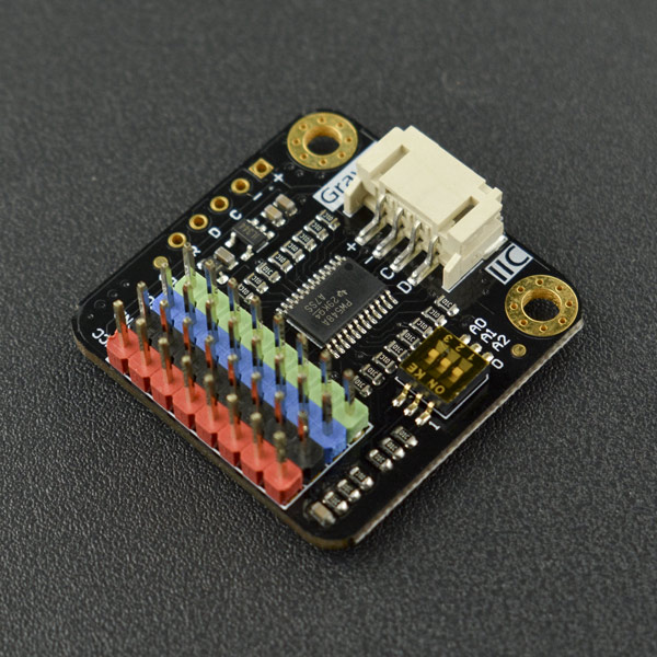
Gravity: I2C扩展器专门用于解决I2C器件地址的冲突,通过这款扩展器的转接,连接到主控板同一个I2C口上的多个相同地址的I2C器件就可以正常通信并使用了。
当你辛辛苦苦找到了所需的传感器,并且想在主控板的I2C口上级联2个或者更多的传感器,但不久你发现传感器的I2C地址竟然是固定的!也就是说,不能在同一个I2C口上使用多个传感器!天啊,这可怎么办啊?我不想再换传感器了。别慌!DFRobot的Gravity: I2C扩展器就是专门解决I2C地址的冲突。通过这个扩展器的转接,你可以在同一个I2C口上接多个相同地址的I2C器件并且正常使用啦。
这个扩展器易于使用,即插即用,无需焊接。1个扩展器上有8个I2C接口,这就意味着:1个扩展器转接后,可以在同一个I2C口上接8个相同地址的器件并正常使用。这个扩展器默认的地址为0x70,地址是可以改变的,根据你的需要,可以在0x70~0x77之内做设定。理论上,在0x70~0x77的地址内可以级联8个扩展器,每个扩展器又可以接8个相同地址的器件,这就实现了同一个I2C口接64个相同地址的器件并正常使用,非常的强大!
 注意:如果只是I2C(SCL、SDA)接口不够用(例如想同时接3个I2C模块而扩展板只有2个接口时)应选择I2C分线模块 [点击跳转]
技术规格
- 工作电压:3.3~5.0V
- 接口类型:PH2.0-4P
- 接口电平:高电平3.3V,低电平0V
- 接口协议:I2C
- I2C时钟频率:100K,400K
- I2C端口数量:8
- 默认I2C地址:0x70(拨码开关全部拨向0)
- I2C地址范围:0x70~0x77
- 产品尺寸:32*32mm
引脚说明
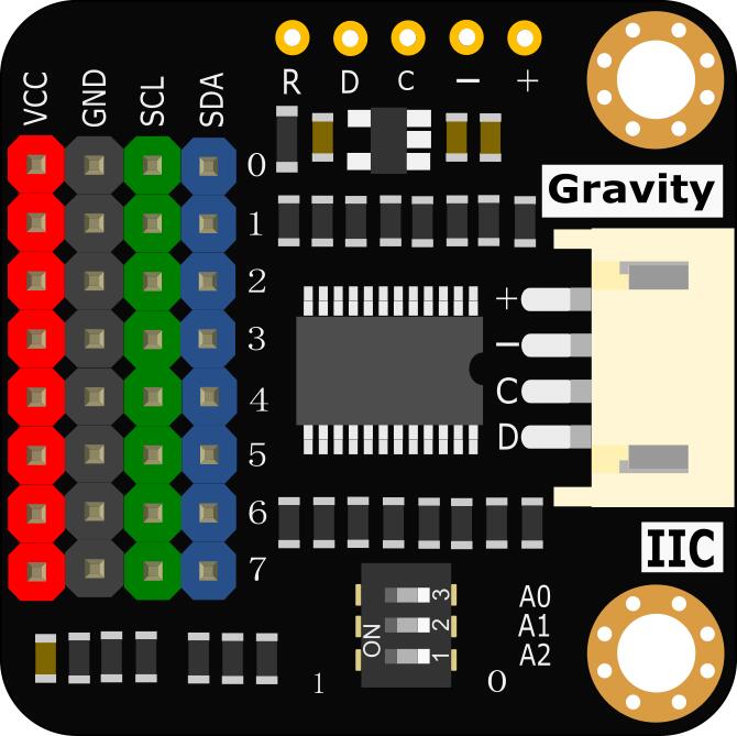
| 标号 | 名称 | 功能描述 |
|---|---|---|
| + | VCC | 电源正极(3.3~5V) |
| - | GND | 电源负极(0V) |
| C | SCL | I2C时钟信号线SCL |
| D | SDA | I2C数据信号线SDA |
| R | RESET | 复位,低电平有效 |
引脚说明
拨码开关说明:
如上图所示,拨码开关默认全部拨向右端,即标有‘0’的一端,此时A2A1A0全部为低电平,因此模块的默认地址为0x70。如拨码开关全部拨向左端,即标有‘1’的一端,此时A2A1A0全部为高电平,此时地址为0x77。您可以根据需要,调节拨码开关来设定地址,可在0x70~0x77内做设定。
使用教程
本教程以两块OLED显示屏为例来演示如何使用这款I2C扩展器。
本例中采用的OLED显示屏,I2C地址是固定的,因此这两块OLED屏幕不能直接同时级联到同一个I2C口上使用。但通过I2C扩展器的转接,主控板的一个I2C口就能正常的同时使用这2块OLED显示屏了。
准备
' 硬件'
- 1 x Arduino UNO(或类似的控制板)
- 1 x Gravity: I2C扩展器
- 2 x Gravity I2C OLED-2864 显示屏(或类似的2块I2C地址一样的模块)
- 3 x Gravity 4pin传感器连接线(或若干杜邦线)
软件
- Arduino IDE(1.0.x或1.8.x),点击下载Arduino IDE
- 下载[https://github.com/DFRobot/DFRobot_I2C_MultiplexerDFRobot_I2C_Multiplexer库]并安装。 如何安装库?
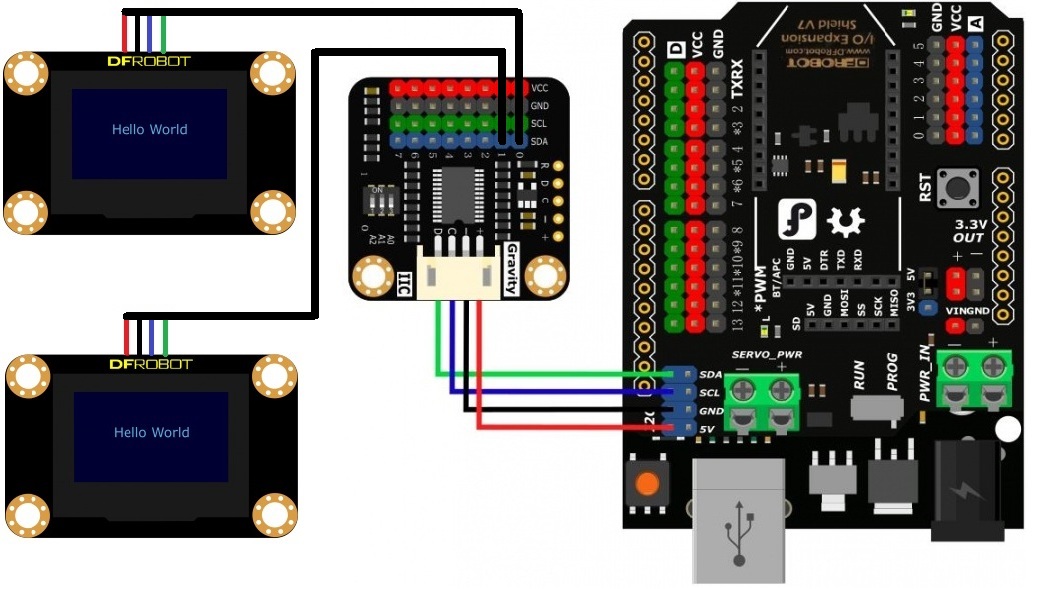
接线图
操作步骤
-
将I2C扩展器的I2C接口(PH2.0-4P贴片座子)连接到Arduino主控板的I2C接口上
-
将两块OLED显示屏的I2C接口分别连接到I2C扩展器的0端口和1端口(彩色排针)
-
Arduino主控板通过USB线与电脑连接,打开Arduino IDE,安装好库文件后,编译Multi_SSD1306.ino并上传到Arduino主控板即可看到样例代码的运行效果
样例代码
请先下载[https://github.com/DFRobot/DFRobot_I2C_MultiplexerDFRobot_I2C_Multiplexer库][https://github.com/DFRobot/DFRobot_SSD1306/archive/master.zipDFRobot_SSD1306库] [https://github.com/DFRobot/DFRobot_Display/archive/master.zipDFRobot_Display库]并安装。 如何安装库?
 /*!
 * @file multiSsd1306.ino
 * @brief Connect two SSD1306 devices to the port 0 and  port 1 on the i2c multiplexer respectively
 * @n     and then connect the I2c multiplexer and Arduino, download this sample. The address of I2C and
 * @n     the name of SSD1306 display module can be seen.
 * @n     Download Display library https://github.com/DFRobot/DFRobot_Display.git
 * @n     Download SSD1306 library https://github.com/DFRobot/DFRobot_SSD1306.git
 * @detail  I2C address selection
 * @n       A2  A1  A0  I2C_addr
 * @n       0   0   0   0x70(default)
 * @n       0   0   1   0x71
 * @n       0   1   0   0x72
 * @n       0   1   1   0x73
 * @n       1   0   0   0x74
 * @n       1   0   1   0x75
 * @n       1   1   0   0x76
 * @n       1   1   1   0x77
 * @copyright   Copyright (c) 2010 DFRobot Co.Ltd (http://www.dfrobot.com)
 * @license     The MIT License (MIT)
 * @author      PengKaixing(kaixing.peng@dfrobot.com)
 * @maintainer  [qsjhyy](yihuan.huang@dfrobot.com)
 * @version  V1.0
 * @date  2022-12-06
 * @url https://github.com/DFRobot/DFRobot_I2C_Multiplexer
 */
#include "DFRobot_SSD1306_I2C.h"
#include "DFRobot_I2C_Multiplexer.h"

/*Create an OLED object, the address is 0x3c*/
DFRobot_SSD1306_I2C OLED(0x3c);

/*Create an I2C Multiplexer object, the address of I2C Multiplexer is 0X70*/
DFRobot_I2C_Multiplexer I2CMulti(&Wire, 0x70);

void setup(void){
  I2CMultiplexer.begin();
  /*Let the OLED on port 0 display characters*/
  /**
   * @brief Enable a specific channel on the I2C multiplexer or disable all channels
   * @param port - Select channel, range: 0 - 8
   * @n 0-7 for enabling the corresponding channel separately, 8 for disabling all channels
   * @note When“multiple multiplexer modules” are used on one I2C bus to connect “sensors with same I2C address”, to avoid conflicts,
   * @n it is necessary to ensure that “the currently used channel”is the only enabled one among “all channels in all multiplexers”
   * @n For instance, when one of the channels in the first multiplexer is enabled, in order to use any channel in the second multiplexer,
   * @n please make sure that the channels in the first multiplexer are all disabled.
   */
  I2CMulti.selectPort(0);
  // Initialize OLED
  OLED.begin();
  OLED.setTextColor(1);
  OLED.setTextSize(2);

  // Set the corrdianate of characters
  OLED.setCursor(0,0);
  // Display characters
  OLED.print("device A");
  OLED.setCursor(0,30);
  OLED.print("addr:0x3C");
  /**
   * Disable all channels to avoid interference when using multiple multiplexer.
   * If only one multiplexer is used, you don't need to do that.
   */
  // I2CMulti.selectPort(8);

  /*Let OLED on port 1 display characters */
  I2CMulti.selectPort(1);
  OLED.begin();
  OLED.setTextColor(1);
  OLED.setTextSize(2);

  OLED.setCursor(0,0);
  OLED.print("device B");
  OLED.setCursor(0,30);
  OLED.print("addr:0x3C");
  /**
   * Disable all channels to avoid interference when using multiple multiplexer.
   * If only one multiplexer is used, you don't need to do that.
   */
  // I2CMulti.selectPort(8);
}

void loop(void){
}
结果
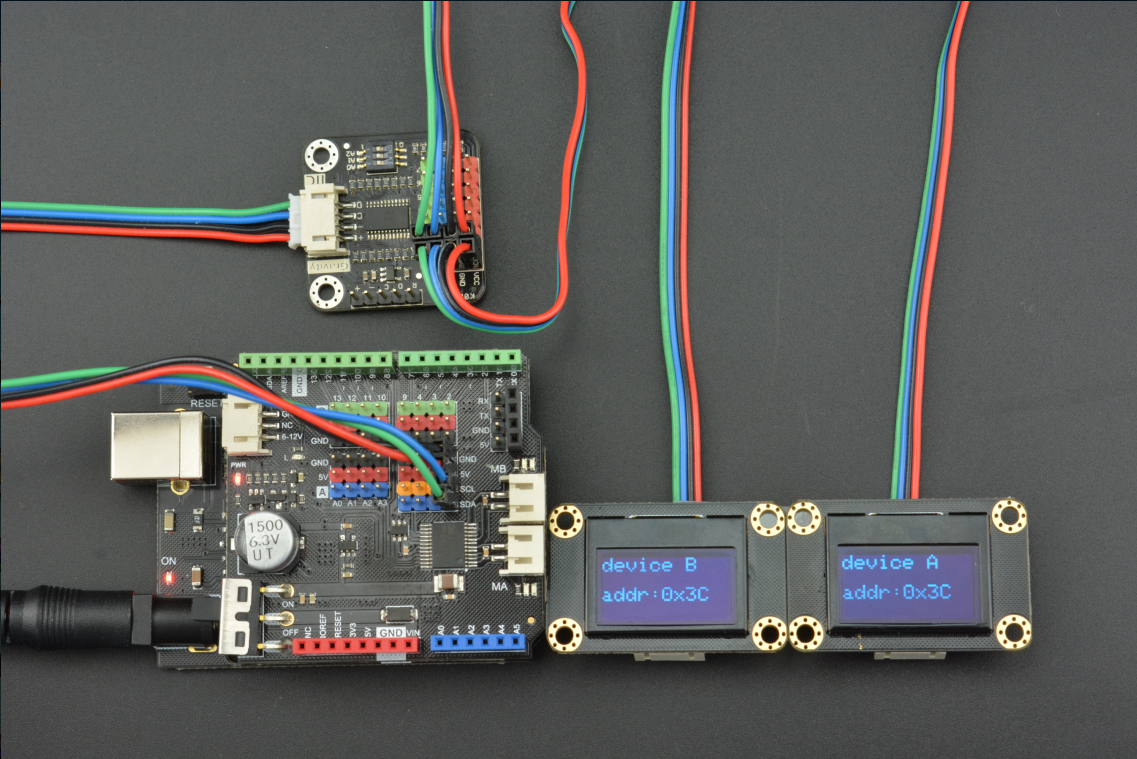
如下图所示,虽然两个OLED屏幕的I2C地址是一样的,但通过I2C扩展器的转接后,都能正常显示了。
程序框架
通过上述的案例,我们已经了解了这款I2C扩展器的硬件和软件是怎么使用的。现在对软件进一步概括,可得出如下的软件框架,该框架可更好的帮助你理解软件库并应用到您的项目中。
    #include "DFRobot_I2CMultiplexer.h"
    #include <Wire.h>

    DFRobot_I2C_Multiplexer I2CMulti(&Wire, 0x70);   //Create an I2C Multiplexer Object;Default Address: 0x70

    void setup(void)
    {
      I2CMulti.selectPort(0);       //Select Port 0
      ...                           //Initialize the I2C Device on Port 0

      I2CMulti.selectPort(1);      //Select Port 1
      ...                          //Initialize the I2C Device on Port 1

       .
       .
       .

      I2CMulti.selectPort(7);      //Select Port 7
      ...                          //Initialize the I2C Device on Port 7
    }

    void loop(void)
    {
      I2CMulti.selectPort(0);       //Select Port 0
      ...                           //Communicate with the I2C Device on Port 0

      I2CMulti.selectPort(1);      //Select Port 1
      ...                          //Communicate with the I2C Device on Port 1

       .
       .
       .

      I2CMulti.selectPort(7);      //Select Port 7
      ...                          //Communicate with the I2C Device on Port 7
    }
Mind+图形化编程
1、下载及安装软件。下载地址:http://www.mindplus.cc 详细教程:Mind+基础wiki教程-软件下载安装
2、切换到“上传模式”。 详细教程:Mind+基础wiki教程-上传模式编程流程
3、“扩展”中选择“主控板”中的“Arduino Uno”,“显示器”中选择“OLED2864显示屏”,“功能模块”选择“I2C级联扩展器”。 详细教程:Mind+基础wiki教程-加载扩展库流程
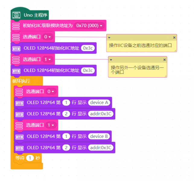
4、进行编程,程序如下图:
5、菜单“连接设备”,“上传到设备”
6、程序上传完毕后,即可看到效果。详细教程:Mind+基础wiki教程-串口打印
 注意:如果只是I2C(SCL、SDA)接口不够用(例如想同时接3个I2C模块而扩展板只有2个接口时)应选择I2C分线模块 [点击跳转]
 **注意:**此级联模块仅Mind+内置I2C模块可级联,其他第三方库如未进行适配则可能无法正常使用。
常见问题
还没有客户对此产品有任何问题,欢迎通过qq或者论坛联系我们!
更多问题及有趣的应用,可以 访问论坛 进行查阅或发帖。 |
