1.概述
Gravity:I2C & UART BC20 NB-IoT & GNSS通信模块是具有NB-IoT低功耗蜂窝通信和GPS/BeiDou双星精确定位功能的物联网通信模块。只要设备所在地区在NB-IoT信号覆盖范围内,无论在室内外均可轻松将开发板或设备采集的各类数据上传至云端,当然也可以通过云端发送指令来远程控制设备,实现云端与真实设备的双向通信与控制,实现“物联”,尤其适用于环境监控站、共享单车、车载定位追踪器等户外物联网应用场景。
此外,模块带有GPS/BeiDou双星精确定位功能,只要将定位天线置于室外即可获取精确的地理坐标和授时信息,实时监控设备的物理位置。用户可通过板载RGB指示灯,清晰了解模块的各类工作状态。为了兼容常见的Arduino、掌控和树莓派等各类3.3V/5V开发板,模块还采用了Gravity I2C & UART复合标准接口,并对这些创客用户常用的开发板在软件上作了全面支持。
注意
- NB-IoT工作于授权频带下,类似于手机2G/3G/4G SIM卡,需要通过SIM卡额外支付通信套餐费用,产品包装附有一张NB-IoT专用SIM卡,可免费使用一年,无需实名,上电即用(流量详见后续NB-IoT SIM卡资费表)。 *注意:不建议使用sendATCMD()修改bc20的波特率,会造成模块无法初始化
2.物联网与NB-IoT简介
物联网(The Internet of things,IoT)顾名思义,就是物与物相连的互联网。这有两层意思:第一,物联网的核心和基础仍然是互联网,是在互联网基础上的延伸和扩展的网络;第二,其用户端延伸和扩展到了任何物品与物品之间,进行信息交换和通信。
窄带物联网(Narrow Band Internet of Things,NB-IoT)是物联网领域一个新兴的技术,主要用于低移动性、小数据量、对时延不敏感的连接服务,其支持低功耗设备在网络中的数据传输,因此也是一种低功耗广域网(Low Power Wide Area Network,LPWAN)通信技术。相对于被逐渐淘汰的2G通信,NB-IoT具有三大优势:
- 广覆盖:海量链接的能力,在同一基站的情况下, NB-IoT 可以比现有无线技术提供 50~100 倍的接入数。一个扇区能够支持,10 万个连接,设备成本与功耗有效降低,网络架构得到优化。
- 大连接:在同样的频段下, NB-IoT比现有的网络增益提升了 20 dB,相当于提升了 100 倍的覆盖面积。
- 低功耗:NB-IoT借助 PSM(Power Saving Mode,节电模式)和 eDRX(Extended Discontinuous Reception,超长非连续接收)可实现更长待机。
3.特性
- NB-IoT低功耗蜂窝通信,广覆盖、大连接、低功耗
- NB-IoT全网通,移动、电信、联通三大运营商全支持
- GPS/BeiDou双星精确定位,设备位置实时监控
- Gravity I2C & UART复合标准接口,兼容各类3.3V/5V开发板
- 板载RGB指示灯,系统状态一目了然
4.应用场景
- 太阳能自动气象/环境监控站
- 车载定位追踪器
- 自动水电气抄表
- 智能路灯管理
- 共享单车
5.技术规格
- 主芯片(通信模组):移远QUECTEL BC20
- 供电电压(VCC):3.3V ~ 5.5V
- 通信频段:B5/B8(移动、电信、联通NB-IoT全网通)
- 传输速率:16.7 kbps(上行),25.5 kbps(下行)
- GNSS导航定位系统:GPS/BeiDou(北斗)双星导航定位
- 通信接口:Gravity I2C & UART 复合接口 (3.3V电平)
- 休眠与低功耗:支持PSM、DRX/eDRX低功耗模式
- 支持DFOTA差分固件升级
- 产品尺寸:47×37 mm
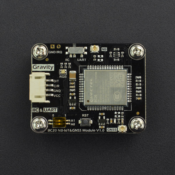
6.接口说明
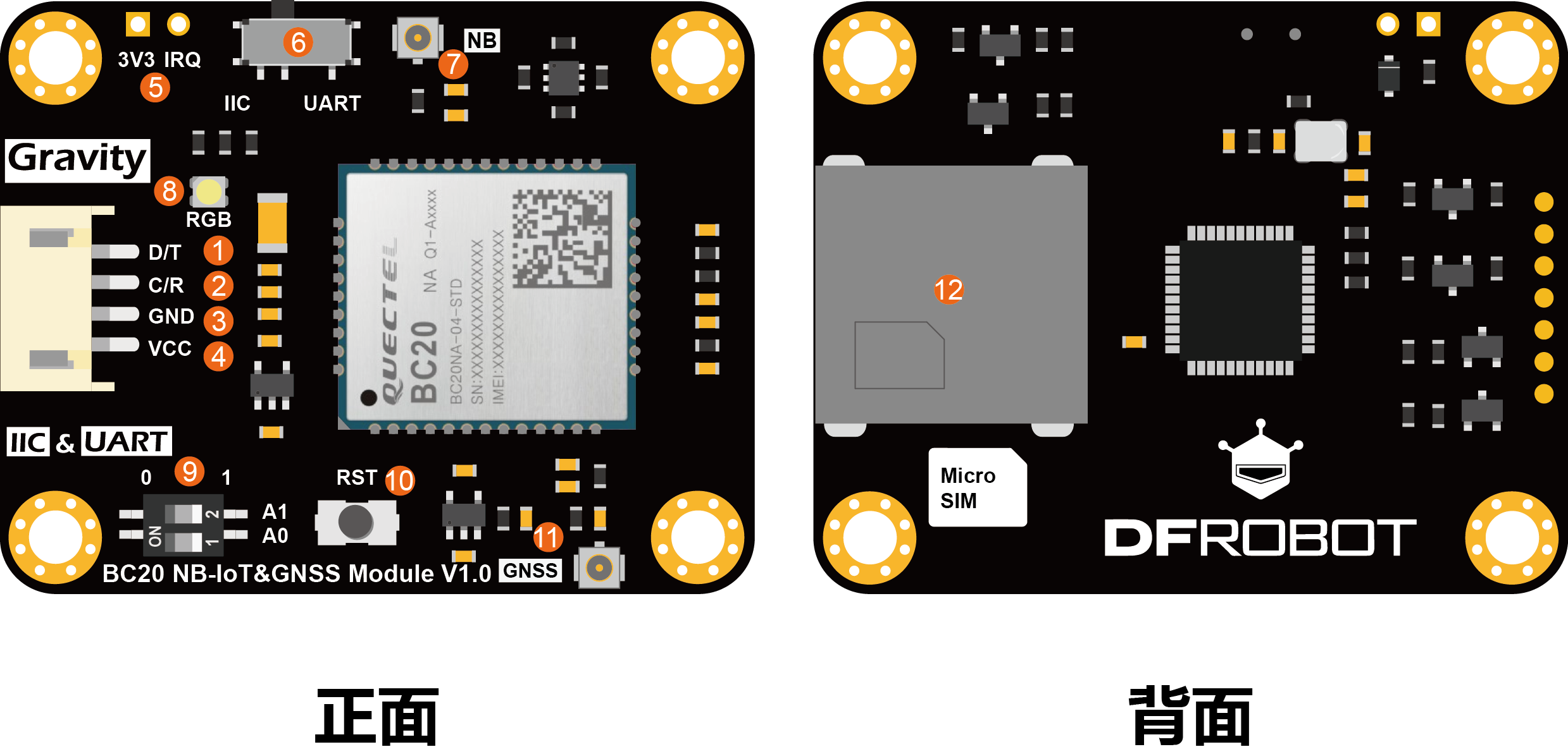
| 标号 | 名称 | 功能描述 |
|---|---|---|
| 1 | D/T | I2C数据线SDA或串口UART发送端TXD(3.3V电平) |
| 2 | C/R | I2C时钟线SCL或串口UART接收端RXD(3.3V电平) |
| 3 | GND | 电源负极 |
| 4 | VCC | 电源正极(3.3~5.5V) |
| 5 | IRQ | PSM休眠唤醒管脚,当模块处于PSM低功耗模式下,将该管脚拉高以唤醒模块。 |
| 6 | I2C/UART | I2C/UART接口选择开关 |
| 7 | NB | NB-IoT天线接口 |
| 8 | RGB | RGB LED全彩指示灯 |
| 9 | / | I2C地址选择拨码。0x30(A0=0,A1=0),0x31(A0=0,A1=1),0x32(A0=1,A1=0),0x33(A0=1,A1=1,默认) |
| 10 | RST | 模块复位按钮 |
| 11 | GNSS | GPS/BeiDou卫星定位天线接口 |
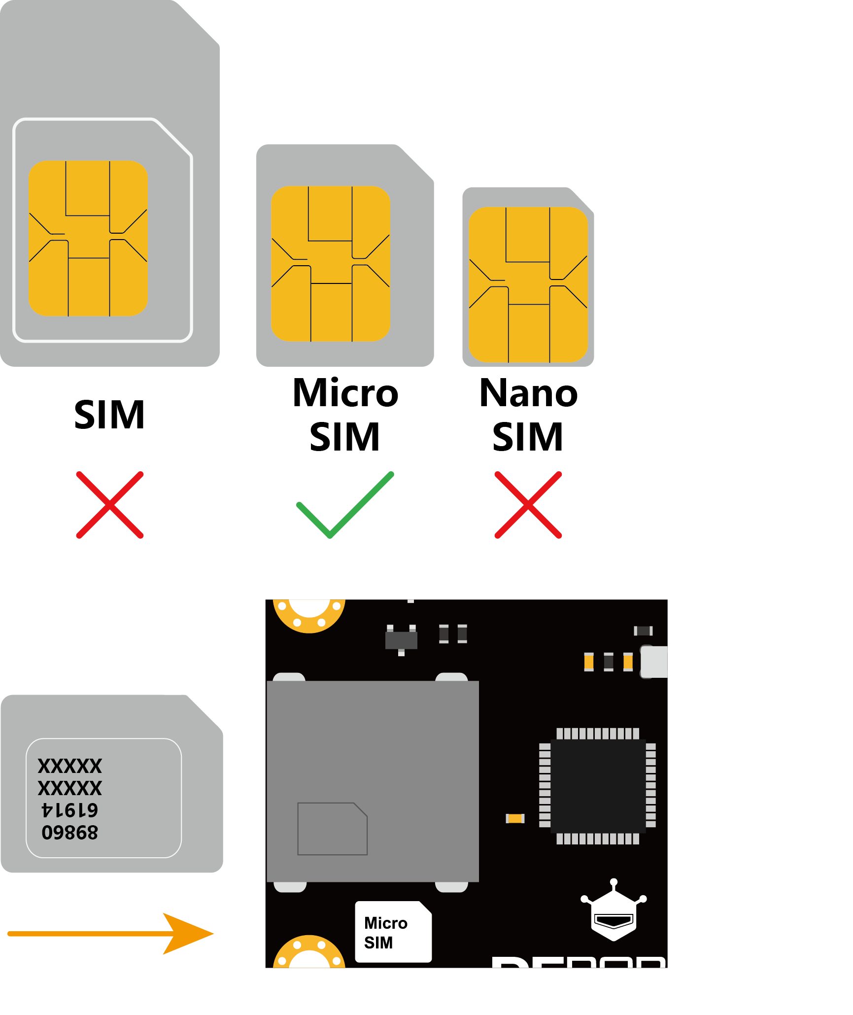
| 12 | Micro SIM | NB-IoT专用SIM卡座(micro SIM) |
7.硬件连接
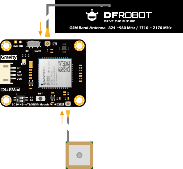
- 连接NB-IoT天线:要进行NB-IoT通信,需要将PCB天线(标有GSM Band Antenna)连接在开发板正面标有NB的u.FL天线连接座。
注意
- PCB天线背后有3M双面胶,撕开保护层后可贴附于非金属表面,在非金属箱体中使用,如:水质监控站或太阳能气象站的塑料防水盒,项目制作常用的亚克力表面。但是不能贴附于金属表面或在金属箱体中使用,否则会严重影响信号质量。
- 连接GNSS导航定位天线:如果需要使用卫星定位功能,可将GNSS陶瓷有源天线连接在开发板背面标有GNSS的u.FL天线连接座。
- 插入SIM卡:NB-IoT通信需要SIM卡,将NB-IoT物联网专用SIM卡从大卡里取出,用手掰成micro SIM卡大小并插入开发板背面标有Micro SIM的SIM卡座中,当卡正确插到底后,会听到轻微的咔一声,SIM卡被扣住。SIM卡座具有防反接功能,当插卡方向不正确,卡座将无法插到底,也无法扣住SIM卡。
8.Arduino使用教程
8.1 准备
硬件
- Arduino UNO控制板 x 1
- Gravity:I2C & UART BC20 NB-IoT & GNSS通信模块 x 1
- Gravity 4P传感器连接线(或若干杜邦线) x 1
软件(Arduino IDE和Mind+图形化编程可二选一)
- Arduino IDE (1.8.x), 点击下载Arduino IDE
- Mind+图形化编程, 点击下载Mind+
- DFRobot_BC20库,点击下载BC20库
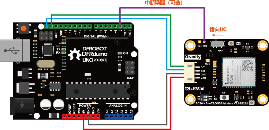
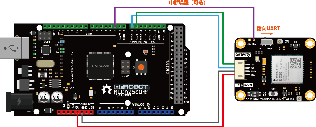
8.2 接线图
- 使用I2C接口时,将开关向I2C左拨。I2C接口适用于各类3.3V/5V开发板。
使用UART接口时,将开关向UART右拨。模块也可通过串口UART与开发板通信,这里以Arduino MEGA2560为例。注意模块的D/T与MEGA2560的RXD,C/R与TXD相连。
8.3 样例代码(Arduino IDE)
配置通信接口
- 每段样例代码开头都有下面一段用于配置通信接口的代码,配合物理接线可配置I2C、UART(硬件)和UART(软件)串口三种不同的通信接口。若不作任何修改,默认使用I2C接口,地址0x33。
/*Communication by IIC*/
#define USE_IIC

/*Communication by HardwareSerial*/
//#define USE_HSERIAL

/*Communication by SoftwareSerial*/
//#define USE_SSERIAL


/******************IIC******************/
#ifdef USE_IIC
/*
   For general controllers. Communicate by IIC
   Connect Instructions
      Controller     |    Module(BC20)
          SDA        |       D/T
          SCL        |       C/R
          GND        |       GND
       5V or 3V3     |       VCC

   IIC address(A0,A1)
     0x30:(A0=0,A1=0)
     0x31:(A0=0,A1=1)
     0x32:(A0=1,A1=0)
     0x33:(A0=1,A1=1) default
*/
DFRobot_BC20_IIC myBC20(0x33);

/******************HardwareSerial******************/
#elif defined(USE_HSERIAL)
/*
   For MEGA2560/ESP32 HardwareSerial
   Connect Instructions
   esp32      |               MEGA Series    |    Module(BC20)
   IO17       |               D16(RX)        |       D/T
   IO16       |               D17(TX)        |       C/R
   GND        |               GND            |       GND
   5V(USB) or 3V3(battery)  | 5V or 3V3      |       VCC
*/
#if defined(ARDUINO_ESP32_DEV)
HardwareSerial Serial2(2);
DFRobot_BC20_Serial myBC20(&Serial2);//ESP32HardwareSerial
#else
DFRobot_BC20_Serial myBC20(&Serial1);//others
#endif

/******************SoftwareSerial******************/
#elif defined(USE_SSERIAL)
/*
    For Arduino Series SoftwareSerial
    Connect Instructions
        UNO     |    Module(BC20)
      PIN_RXD   |       D/T
      PIN_TXD   |       C/R
        GND     |       GND
     5V or 3V3  |       VCC
*/
#define PIN_TXD   3
#define PIN_RXD   4
SoftwareSerial ss(PIN_RXD, PIN_TXD);
DFRobot_BC20_SW_Serial myBC20(&ss);
#endif- 使用I2C接口时,若出现IIC地址冲突,可修改下面一条语句中的参数0x33以改变IIC地址。可使用的I2C地址共有4个,拨动模块上的拨码开关,调整A0和A1,并修改如下相应I2C地址,复位程序完成修改。
- 0x30:(A0=0,A1=0)
- 0x31:(A0=0,A1=1)
- 0x32:(A0=1,A1=0)
- 0x33:(A0=1,A1=1) 默认
DFRobot_BC20_IIC myBC20(0x33);- 使用UART(硬件)接口时,波特率为115200,如下取消#define USE_HSERIAL注释,注释掉另外两个宏定义#define,完成硬串口的配置。
/*Communication by IIC*/
//#define USE_IIC

/*Communication by HardwareSerial*/
#define USE_HSERIAL

/*Communication by SoftwareSerial*/
//#define USE_SSERIAL
- 使用UART(软件)接口时,波特率为9600,如下取消#define USE_HSERIAL,注释掉另外两个宏定义#define,完成软串口的配置。
/*Communication by IIC*/
//#define USE_IIC

/*Communication by HardwareSerial*/
//#define USE_HSERIAL

/*Communication by SoftwareSerial*/
#define USE_SSERIAL
- 调整UART(软件)接口管脚,修改如下两个宏定义#define PIN_TXD和#define PIN_RXD的值,前者配置主控的发送端TXD(与模块的接收端相连),后者配置主控的接收端RXD(与模块的发送端相连)。
#define PIN_TXD   3
#define PIN_RXD   4
SoftwareSerial ss(PIN_RXD, PIN_TXD);
DFRobot_BC20_SW_Serial myBC20(&ss);
测量NB-IoT的信号强度
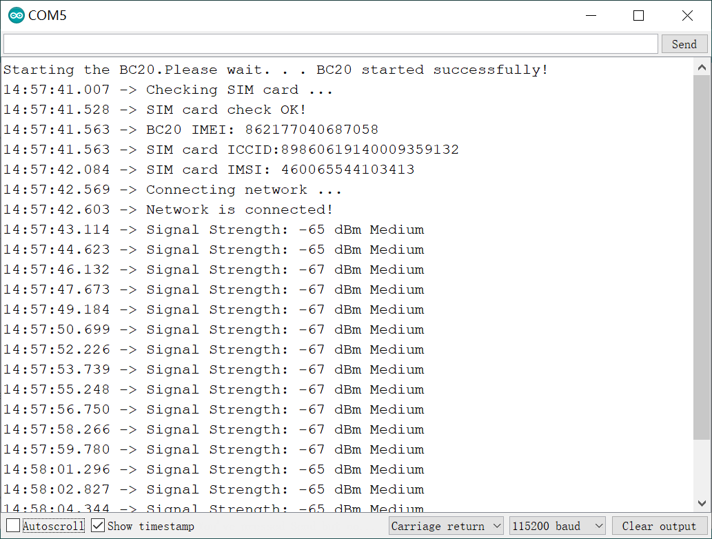
- 按照连线图,连接好NB-IoT天线,插入SIM卡,并与主控板相连。
- 将下面样例代码上传至主控板。(默认使用I2C接口,地址0x33。)
- 打开串口监控器,波特率设为115200。
/*!
   @file SignalDetector.ino

   @n This example detects the NB-IoT signal strength

   @Copyright   Copyright (c) 2010 DFRobot Co.Ltd (http://www.dfrobot.com)
   @licence     The MIT License (MIT)
   @author      [Peng kaixing](kaixing.peng@dfrobot.com)
   @version  V1.0
   @date   2019-12-18
   @get from https://www.dfrobot.com
*/

#include <DFRobot_BC20_Gravity.h>

/*7 colors are available*/
#define  RED 0
#define  BLUE 1
#define  GREEN 2
#define  YELLOW 3
#define  PURPLE 4
#define  CYAN 5
#define  WHITE 6

/*Communication by IIC*/
#define USE_IIC

/*Communication by HardwareSerial*/
//#define USE_HSERIAL

/*Communication by SoftwareSerial*/
//#define USE_SSERIAL


/******************IIC******************/
#ifdef USE_IIC
/*
   For general controllers. Communicate by IIC
   Connect Instructions
      Controller     |    Module(BC20)
          SDA        |       D/T
          SCL        |       C/R
          GND        |       GND
       5V or 3V3     |       VCC

   IIC address(A0,A1)
     0x30:(A0=0,A1=0)
     0x31:(A0=0,A1=1)
     0x32:(A0=1,A1=0)
     0x33:(A0=1,A1=1) default
*/
DFRobot_BC20_IIC myBC20(0x33);

/******************HardwareSerial******************/
#elif defined(USE_HSERIAL)
/*
   For MEGA2560/ESP32 HardwareSerial
   Connect Instructions
   esp32      |               MEGA Series    |    Module(BC20)
   IO17       |               D16(RX)        |       D/T
   IO16       |               D17(TX)        |       C/R
   GND        |               GND            |       GND
   5V(USB) or 3V3(battery)  | 5V or 3V3      |       VCC
*/
#if defined(ARDUINO_ESP32_DEV)
HardwareSerial Serial2(2);
DFRobot_BC20_Serial myBC20(&Serial2);//ESP32HardwareSerial
#else
DFRobot_BC20_Serial myBC20(&Serial1);//others
#endif

/******************SoftwareSerial******************/
#elif defined(USE_SSERIAL)
/*
    For Arduino Series SoftwareSerial
    Connect Instructions
        UNO     |    Module(BC20)
      PIN_RXD   |       D/T
      PIN_TXD   |       C/R
        GND     |       GND
     5V or 3V3  |       VCC
*/
#define PIN_TXD   3
#define PIN_RXD   4
SoftwareSerial ss(PIN_RXD, PIN_TXD);
DFRobot_BC20_SW_Serial myBC20(&ss);
#endif

/*
   The signal strength is indicated by both numerical value in dBm
   and the flashing LED:
   Strong signal - fast flash
   Medium signal - slow flash
   Weak signal - burst flash.
*/
static void NB_Signal_Fun() {

  /*Get the NB-IoT signal strength.*/
  myBC20.getSQ();

  /*Signal quality RSSI<10, WEAK signal strength*/
  myBC20.changeColor(WHITE);
  if (sSQ.rssi < 10 || sSQ.rssi == 99) {
    if (sSQ.rssi == 99) {
      Serial.println("Signal not detectable");
    } else if (sSQ.rssi == 0) {
      Serial.println("Signal Strength: -113 dBm or less");
    } else {
      Serial.print("Signal Strength: ");
      Serial.print((sSQ.rssi - 2) * 2 - 109);
      Serial.println(" dBm Weak");
    }

    //Burst flash
    myBC20.LED_ON();
    delay(100);
    myBC20.LED_OFF();
    delay(900);
  }

  /*Signal quality 10<=RSSI<25, MEDIUM signal strength*/
  else if (sSQ.rssi >= 10  && sSQ.rssi < 25) {
    Serial.print("Signal Strength: ");
    Serial.print((sSQ.rssi - 2) * 2 - 109);
    Serial.println(" dBm Medium");

    //Slow flash
    myBC20.LED_ON();
    delay(500);
    myBC20.LED_OFF();
    delay(500);
  }

  /*Signal quality RSSI>=25, STRONG signal strength*/
  else if (sSQ.rssi >= 25) {
    if (sSQ.rssi < 31) {
      Serial.print("Signal Strength: ");
      Serial.print((sSQ.rssi - 2) * 2 - 109);
      Serial.println(" dBm Strong");
    } else if (sSQ.rssi == 31) {
      Serial.print("Signal Strength: -51 dBm or greater");
    }

    //Fast flash
    for (int i = 0; i < 5 ; i++) {
      myBC20.LED_ON();
      delay(100);
      myBC20.LED_OFF();
      delay(100);
    }
  }
  else {
    ;
  }
}

void setup() {
  Serial.begin(115200);
  myBC20.LED_OFF();

  /*Initialize BC20*/
  Serial.print("Starting the BC20.Please wait. . . ");
  myBC20.changeColor(RED);
  while (!myBC20.powerOn()) {
    Serial.print(".");
    myBC20.LED_ON();
    delay(500);
    myBC20.LED_OFF();
    delay(500);
  }
  Serial.println("BC20 started successfully!");

  /*Check whether SIM card is inserted*/
  Serial.println("Checking SIM card ...");
  myBC20.changeColor(GREEN);
  while (!myBC20.checkNBCard()) {
    Serial.println("Please insert the NB SIM card !");
    myBC20.LED_ON();
    delay(500);
    myBC20.LED_OFF();
    delay(500);
  }
  Serial.println("SIM card check OK!");

  /*Print IMEI, ICCID and IMSI*/
  myBC20.getGSN(IMEI);
  Serial.print("BC20 IMEI: ");
  Serial.println(sGSN.imei);
  Serial.print("SIM card ICCID:");
  Serial.println(myBC20.getQCCID());
  Serial.print("SIM card IMSI: ");
  Serial.println((char *)myBC20.getIMI());

  /**
     The module will automatically attempt to connect to the network (mobile station).
     Check whether it is connected to the network.
  */
  Serial.println("Connecting network ...");
  myBC20.changeColor(BLUE);
  while (myBC20.getGATT() == 0) {
    Serial.print(".");
    myBC20.LED_ON();
    delay(500);
    myBC20.LED_OFF();
    delay(500);
  }
  Serial.println("Network is connected!");
}

void loop() {
  /*Get local NB-IoT signal strength and print*/
  NB_Signal_Fun();
}
结果
程序通过串口打印当前环境(接收到的)NB-IoT信号强度RSSI(单位dBm,通常为负值,测量范围:-113 ~ -51 dBm,数值越大信号越强)。
通过RGB(白光)闪烁的快慢来表示信号强度,分为三级:
- 爆闪:信号弱(-95 dBm或以下),0.1s亮,0.9s灭。
- 慢闪:信号中等(-93 ~ - 65 dBm之间),0.5s亮,0.5s灭。
- 快闪:信号强(- 63 dBm或以上),0.1s亮,0.1s灭。
校准日期与时间
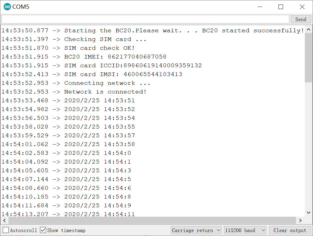
- 按照连线图,连接好NB-IoT天线,插入SIM卡,并与主控板相连。
- 将下面样例代码上传至主控板。(默认使用I2C接口,地址0x33。)
- 打开串口监控器,波特率设为115200。
/*!
   @file CalLocalTime_NB.ino

   @brief Get local date & time by NB-IoT (moblie station)

   @copyright   Copyright (c) 2010 DFRobot Co.Ltd (http://www.dfrobot.com)
   @licence     The MIT License (MIT)
   @author      [PengKaixing](kaixing.peng@dfrobot.com)
   @date  2019-07-18
   @get from https://www.dfrobot.com
*/
#include <DFRobot_BC20_Gravity.h>

/*7 colors are available*/
#define  RED 0
#define  BLUE 1
#define  GREEN 2
#define  YELLOW 3
#define  PURPLE 4
#define  CYAN 5
#define  WHITE 6

/*Communication by IIC*/
#define USE_IIC

/*Communication by HardwareSerial*/
//#define USE_HSERIAL

/*Communication by SoftwareSerial*/
//#define USE_SSERIAL


/******************IIC******************/
#ifdef USE_IIC
/*
   For general controllers. Communicate by IIC
   Connect Instructions
      Controller     |    Module(BC20)
          SDA        |       D/T
          SCL        |       C/R
          GND        |       GND
       5V or 3V3     |       VCC

   IIC address(A0,A1)
     0x30:(A0=0,A1=0)
     0x31:(A0=0,A1=1)
     0x32:(A0=1,A1=0)
     0x33:(A0=1,A1=1) default
*/
DFRobot_BC20_IIC myBC20(0x33);

/******************HardwareSerial******************/
#elif defined(USE_HSERIAL)
/*
   For MEGA2560/ESP32 HardwareSerial
   Connect Instructions
   esp32      |               MEGA Series    |    Module(BC20)
   IO17       |               D16(RX)        |       D/T
   IO16       |               D17(TX)        |       C/R
   GND        |               GND            |       GND
   5V(USB) or 3V3(battery)  | 5V or 3V3      |       VCC
*/
#if defined(ARDUINO_ESP32_DEV)
HardwareSerial Serial2(2);
DFRobot_BC20_Serial myBC20(&Serial2);//ESP32HardwareSerial
#else
DFRobot_BC20_Serial myBC20(&Serial1);//others
#endif

/******************SoftwareSerial******************/
#elif defined(USE_SSERIAL)
/*
    For Arduino Series SoftwareSerial
    Connect Instructions
        UNO     |    Module(BC20)
      PIN_RXD   |       D/T
      PIN_TXD   |       C/R
        GND     |       GND
     5V or 3V3  |       VCC
*/
#define PIN_TXD   3
#define PIN_RXD   4
SoftwareSerial ss(PIN_RXD, PIN_TXD);
DFRobot_BC20_SW_Serial myBC20(&ss);
#endif

void getLocalTime()
{
  /* Check whether the data is legal */
  myBC20.changeColor(PURPLE);
  while (myBC20.getCLK()) {
    if (sCLK.Year > 2000) {
      break;
    }
    Serial.print(".");
    myBC20.LED_ON();
    delay(500);
    myBC20.LED_OFF();
    delay(500);
  }

  //Date
  Serial.print((String)sCLK.Year + "/" + (String)sCLK.Month + "/" + (String)sCLK.Day + " ");
  //Time
  Serial.println((String)sCLK.Hour + ":" + (String)sCLK.Minute + ":" + (String)sCLK.Second);
}

void setup()
{
  Serial.begin(115200);
  myBC20.LED_OFF();

  /*Initialize BC20*/
  Serial.print("Starting the BC20.Please wait. . . ");
  myBC20.changeColor(RED);
  while (!myBC20.powerOn()) {
    Serial.print(".");
    myBC20.LED_ON();
    delay(500);
    myBC20.LED_OFF();
    delay(500);
  }
  Serial.println("BC20 started successfully!");

  /*Check whether SIM card is inserted*/
  Serial.println("Checking SIM card ...");
  myBC20.changeColor(GREEN);
  while (!myBC20.checkNBCard()) {
    Serial.println("Please insert the NB SIM card !");
    myBC20.LED_ON();
    delay(500);
    myBC20.LED_OFF();
    delay(500);
  }
  Serial.println("SIM card check OK!");

  /*Print IMEI, ICCID and IMSI*/
  myBC20.getGSN(IMEI);
  Serial.print("BC20 IMEI: ");
  Serial.println(sGSN.imei);
  Serial.print("SIM card ICCID:");
  Serial.println(myBC20.getQCCID());
  Serial.print("SIM card IMSI: ");
  Serial.println((char *)myBC20.getIMI());

  /**
     The module will automatically attempt to connect to the network (mobile station).
     Check whether it is connected to the network.
  */
  Serial.println("Connecting network ...");
  myBC20.changeColor(BLUE);
  while (myBC20.getGATT() == 0) {
    Serial.print(".");
    myBC20.LED_ON();
    delay(500);
    myBC20.LED_OFF();
    delay(500);
  }
  Serial.println("Network is connected!");
}

void loop()
{
  /*Get local date & time and print*/
  getLocalTime();
  delay(1000);
}
结果
程序每隔1s通过串口打印当前地区的日期(年月日)、时间(时分秒)和时区(格林威治时间GMT+XX)。
日期、时间和时区均获取于附近的蜂窝基站,而并非某个网络服务器。
获取物理位置坐标(精简版)
- 按照连线图,连接好NB-IoT天线,插入SIM卡,并与主控板相连。
- 将下面样例代码上传至主控板。(默认使用I2C接口,地址0x33)
- 打开串口监控器,波特率设为115200。
- 更多GNSS定位相关样例详见Arduino IDE中文件->示例->所有开发版示例->DFRobot_BC20->GNSS。
/*!
   @file getGNSS_simple.ino
   @brief Print all the GNSS info available in BC20.
   @This DEMO can be used for master control boards with small RAM space, such as UNO and leanordo
   @copyright   Copyright (c) 2010 DFRobot Co.Ltd (http://www.dfrobot.com)
   @licence     The MIT License (MIT)
   @author      [Peng Kaixing](kaixing.peng@dfrobot.com)
   @version  V1.0
   @date  2019-10-29
   @get from https://www.dfrobot.com
*/
#include <DFRobot_BC20_Gravity.h>

/* 7 colors are available */
#define  RED 0
#define  BLUE 1
#define  GREEN 2
#define  YELLOW 3
#define  PURPLE 4
#define  CYAN 5
#define  WHITE 6

/*Communication by IIC*/
#define USE_IIC

/*Communication by HardwareSerial*/
//#define USE_HSERIAL

/*Communication by SoftwareSerial*/
//#define USE_SSERIAL


/******************IIC******************/
#ifdef USE_IIC
/*
   For general controllers. Communicate by IIC
   Connect Instructions
      Controller     |    Module(BC20)
          SDA        |       D/T
          SCL        |       C/R
          GND        |       GND
       5V or 3V3     |       VCC

   IIC address(A0,A1)
     0x30:(A0=0,A1=0)
     0x31:(A0=0,A1=1)
     0x32:(A0=1,A1=0)
     0x33:(A0=1,A1=1) default
*/
DFRobot_BC20_IIC myBC20(0x33);

/******************HardwareSerial******************/
#elif defined(USE_HSERIAL)
/*
   For MEGA2560/ESP32 HardwareSerial
   Connect Instructions
   esp32      |               MEGA Series    |    Module(BC20)
   IO16       |               D16(RX)        |       D/T
   IO17       |               D17(TX)        |       C/R
   GND        |               GND            |       GND
   5V(USB) or 3V3(battery)  | 5V or 3V3      |       VCC
*/
#if defined(ARDUINO_ESP32_DEV)
HardwareSerial Serial2(2);
DFRobot_BC20_Serial myBC20(&Serial2);//ESP32HardwareSerial
#else
DFRobot_BC20_Serial myBC20(&Serial2);//others
#endif

/******************SoftwareSerial******************/
#elif defined(USE_SSERIAL)
/*
    For Arduino Series SoftwareSerial
    Connect Instructions
        UNO     |    Module(BC20)
      PIN_RXD   |       D/T
      PIN_TXD   |       C/R
        GND     |       GND
     5V or 3V3  |       VCC
*/
#define PIN_TXD   3
#define PIN_RXD   4
SoftwareSerial ss(PIN_RXD,PIN_TXD);
DFRobot_BC20_SW_Serial myBC20(&ss);
#endif

void Display_Location_Information() {

  /*
     UTC time of the anchor point
  */
  Serial.print("Time:  ");
  Serial.print(sCLK.Hour);
  Serial.print(":");
  Serial.print(sCLK.Minute);
  Serial.print(":");
  Serial.println(sCLK.Second);

  Serial.print("Latitude:  ");
  Serial.print(sGGNS2.LatitudeVal,6);
  Serial.print(" deg ");
  Serial.println(sGGNS2.LatitudeDir());
  Serial.print("Longitude:  ");
  Serial.print(sGGNS2.LongitudeVal,6);
  Serial.print(" deg ");
  Serial.println(sGGNS2.LongitudeDir());
  Serial.print("Altitude:  ");
  Serial.print(sGGNS2.Altitude);
  Serial.println(" m");
  Serial.print("Fix Status: ");
  Serial.println(sGGNS2.Status());
  Serial.print("StatelliteNum: ");
  Serial.print(sGGNS2.StatelliteNum);
  Serial.println(" in Used");
  Serial.print("HDOP: ");
  Serial.println(sGGNS2.HDOP);
  Serial.println("");
}

void setup() {
  Serial.begin(115200);
  myBC20.LED_OFF();

  /*Initialize BC20*/
  Serial.print("Starting the BC20.Please wait. . . ");
  myBC20.changeColor(RED);
  while (!myBC20.powerOn()) {
    Serial.print(".");
    myBC20.LED_ON();
    delay(500);
    myBC20.LED_OFF();
    delay(500);
  }
  Serial.println("BC20 started successfully!");

  /* Disable sleep mode */
  myBC20.configSleepMode(eSleepMode_Disable);

  /*Power up GNSS*/
  Serial.print("Turning on GNSS ... ");
  myBC20.setQGNSSC(ON);
  myBC20.changeColor(YELLOW);
  if (myBC20.getQGNSSC() == OFF) {
    Serial.print(".");
    myBC20.LED_ON();
    delay(500);
    myBC20.LED_OFF();
    delay(500);
  }
  Serial.println("GNSS is ON.");
  myBC20.changeColor(CYAN);
}

void loop() {
  myBC20.getQGNSSRD2();
  Display_Location_Information();
  myBC20.clearGPS();

  myBC20.LED_ON();
  delay(500);
  myBC20.LED_OFF();
#ifndef ARDUINO_ESP32_DEV
  delay(500);
#else
  delay(5000);
#endif
}
结果
GNSS定位需要一定时间进行寻星,首次上电通常需要30s以上才能获取有效的定位信息。
程序通过串口打印GNSS定位的关键信息:
- 时间(Time): 7:29:45表示当地时间为15时14分1秒(北京时间)**。需要注意的是,这里7时是指格林尼治时间GMT+0,北京时间为GMT+8,需要用户额外加上8小时才能得到北京时间,也可以自行根据经纬度计算出当地时区,从而自动换算出当地时间。
- 纬度坐标(Latitude):31.204355 deg N表示北纬31.204355°,精确到小数点后6位。南纬用S表示。
- 经度坐标(Longitude):121.599090 deg E表示东经121.599090°,精确到小数点后6位。西经用W表示。
- 海拔高度(Altitude):单位m。WGS84 椭球面为基准。
- 定位状态(Fix Status):为DGPS或者GNSS时,代表成功定位。
- 水平精度因子(HDOP):水平分量的相对误差,为纬度和经度等误差平方和的开根号值。数值越小,代表经纬坐标精度越高,一般小于3比较理想。
获取物理位置坐标(详细版)
- 该样例适用于Arduino MEGA,ESP32、ESP8266系列等RAM较大的主控板。Arduino UNO和Leonardo由于RAM较小,使用该样例后数据可能出错,不建议使用该样例。
- 按照连线图,连接好NB-IoT天线,插入SIM卡,并与主控板相连。
- 将下面样例代码上传至主控板。(默认使用IIC接口,地址0x33)
- 打开串口监控器,波特率设为115200。
- 更多GNSS定位相关样例详见Arduino IDE中文件->示例->所有开发版示例->DFRobot_BC20->GNSS。
/*!
   @file getGNSS_detail.ino
   @brief Print all the GNSS info available in BC20.
   @This DEMO can be used for large RAM master boards like ESP32, MEGA2560.
   @copyright   Copyright (c) 2010 DFRobot Co.Ltd (http://www.dfrobot.com)
   @licence     The MIT License (MIT)
   @author      [Peng Kaixing](kaixing.peng@dfrobot.com)
   @version  V1.0
   @date  2019-10-29
   @get from https://www.dfrobot.com
*/
#include <DFRobot_BC20_Gravity.h>

/* 7 colors are available */
#define  RED 0
#define  BLUE 1
#define  GREEN 2
#define  YELLOW 3
#define  PURPLE 4
#define  CYAN 5
#define  WHITE 6

/*Communication by IIC*/
#define USE_IIC

/*Communication by HardwareSerial*/
//#define USE_HSERIAL

/*Communication by SoftwareSerial*/
//#define USE_SSERIAL


/******************IIC******************/
#ifdef USE_IIC
/*
   For general controllers. Communicate by IIC
   Connect Instructions
      Controller     |    Module(BC20)
          SDA        |       D/T
          SCL        |       C/R
          GND        |       GND
       5V or 3V3     |       VCC

   IIC address(A0,A1)
     0x30:(A0=0,A1=0)
     0x31:(A0=0,A1=1)
     0x32:(A0=1,A1=0)
     0x33:(A0=1,A1=1) default
*/
DFRobot_BC20_IIC myBC20(0x33);

/******************HardwareSerial******************/
#elif defined(USE_HSERIAL)
/*
   For MEGA2560/ESP32 HardwareSerial
   Connect Instructions
   esp32      |               MEGA Series    |    Module(BC20)
   IO16       |               D17(RX)        |       D/T
   IO17       |               D16(TX)        |       C/R
   GND        |               GND            |       GND
   5V(USB) or 3V3(battery)  | 5V or 3V3      |       VCC
*/
#if defined(ARDUINO_ESP32_DEV)
HardwareSerial Serial2(2);
DFRobot_BC20_Serial myBC20(&Serial2);//ESP32HardwareSerial
#else
DFRobot_BC20_Serial myBC20(&Serial2);//others
#endif

/******************SoftwareSerial******************/
#elif defined(USE_SSERIAL)
/*
    For Arduino Series SoftwareSerial
    Connect Instructions
        UNO     |    Module(BC20)
      PIN_RXD   |       D/T
      PIN_TXD   |       C/R
        GND     |       GND
     5V or 3V3  |       VCC
*/
#define PIN_TXD   3
#define PIN_RXD   4
SoftwareSerial ss(PIN_RXD,PIN_TXD);
DFRobot_BC20_SW_Serial myBC20(&ss);
#endif

void Display_Location_Information() {

  /*
     UTC time of the anchor point
  */
  Serial.print("Time:\t\t");
  Serial.print(sCLK.Year);
  Serial.print("/");
  Serial.print(sCLK.Month);
  Serial.print("/");
  Serial.print(sCLK.Day);
  Serial.print("  ");
  Serial.print(sCLK.Hour);
  Serial.print(":");
  Serial.print(sCLK.Minute);
  Serial.print(":");
  Serial.println(sCLK.Second);

  Serial.print("Latitude:\t");
  Serial.print(sGGNS.LatitudeVal, 6);
  Serial.print(" deg ");
  Serial.println(sGGNS.LatitudeDir);
  Serial.print("Longitude:\t");
  Serial.print(sGGNS.LongitudeVal, 6);
  Serial.print(" deg ");
  Serial.println(sGGNS.LongitudeDir);
  Serial.print("Altitude:\t");
  Serial.print(sGGNS.Altitude, 1);
  Serial.println(" m");
  Serial.print("Speed:\t\t");
  Serial.print(sGGNS.Speed);
  Serial.println(" km/h");
  Serial.print("Heading:\t");
  Serial.print(sGGNS.Heading);
  Serial.println(" deg");
  Serial.print("Status:\t\t");
  Serial.println(sGGNS.FixStatus);
  Serial.print("PDOP:\t\t");
  Serial.println(sGGNS.PDOP);
  Serial.print("HDOP:\t\t");
  Serial.println(sGGNS.HDOP);
  Serial.print("VDOP:\t\t");
  Serial.println(sGGNS.VDOP);
  Serial.println();
}

void Display_Satellite_Information() {
  Serial.print(sSAT.NUM);
  Serial.println(" in view.");
  Serial.print(sSAT2.USE);
  Serial.println(" in used.");
  Serial.print("PRN\t");
  Serial.print("Elev(deg)\t");
  Serial.print("Azim(deg)\t");
  Serial.print("SNR(dBHz)\t");
  Serial.print("SYS\t");
  Serial.println("Used");
  for (uint8_t i = 0; i < sSAT.NUM; i++) {
    Serial.print(sSAT2.data[i].PRN);
    Serial.print("\t");
    Serial.print(sSAT2.data[i].Elev);
    Serial.print("\t\t");
    Serial.print(sSAT2.data[i].Azim);
    Serial.print("\t\t");
    Serial.print(sSAT2.data[i].SNR);
    Serial.print("\t\t");
    Serial.print(sSAT2.data[i].SYS);
    Serial.print("\t");
    Serial.println(sSAT2.data[i].Status);
  }
  Serial.println("");
}

void setup() {
  Serial.begin(115200);
  myBC20.LED_OFF();

  /*Initialize BC20*/
  Serial.print("Starting the BC20.Please wait. . . ");
  myBC20.changeColor(RED);
  while (!myBC20.powerOn()) {
    Serial.print(".");
    myBC20.LED_ON();
    delay(500);
    myBC20.LED_OFF();
    delay(500);
  }
  Serial.println("BC20 started successfully!");

  /* Disable sleep mode */
  myBC20.configSleepMode(eSleepMode_Disable);

  /*Power up GNSS*/
  Serial.print("Turning on GNSS ... ");
  myBC20.setQGNSSC(ON);
  myBC20.changeColor(YELLOW);
  if (myBC20.getQGNSSC() == OFF) {
    Serial.print(".");
    myBC20.LED_ON();
    delay(500);
    myBC20.LED_OFF();
    delay(500);
  }
  Serial.println("GNSS is ON.");
  myBC20.changeColor(CYAN);
}

void loop() {

  /**
     Is used to obtain the specified satellite information, and the parameter is used to specify the type of information to be obtained.
     The parameter is selected as follows:
  */
  myBC20.getQGNSSRD();
  Display_Location_Information();
  Display_Satellite_Information();
  myBC20.clearGPS();

  myBC20.LED_ON();
  delay(500);
  myBC20.LED_OFF();
#ifndef ARDUINO_ESP32_DEV
  delay(500);
#else
  delay(5000);
#endif
}
结果
GNSS定位需要一定时间进行寻星,首次上电通常需要30s以上才能获取有效的定位信息。
程序通过串口打印GNSS定位的所有信息,第一部分为定位信息:
- 时间与日期(Time):2020/3/10 11:58:0表示当地时间与日期为2020年3月10日,19时58分0秒(北京时间)。需要注意的是,这里11时是指格林尼治时间GMT+0,北京时间为GMT+8,需要用户手动加上8小时才能得到北京时间,也可以自行根据经纬度计算出当地时区,从而自动换算出当地时间。
- 纬度坐标(Latitude):单位,度。30.668159 deg N表示北纬30.668159°,精确到小数点后6位。南纬用S表示。
- 经度坐标(Longitude):单位,度。103.809471 deg E表示东经103.809471°,精确到小数点后6位。西经用W表示。
- 海拔高度(Altitude):单位,m。WGS84 椭球面为基准。
- 对地速度(Speed):单位,km/h。由于数据会有一定抖动,可能出现在静止状态时也不为零的情况。
- 对地朝向(Heading):单位,度。
- 定位状态(Status):为2D fix或3D fix,代表成功定位。
- N:数据无效
- 2D fix,3D fix:2维定位,3维定位。
- 位置精度因子(PDOP):位置精度的相对误差(0.5--99.9);为纬度、经度和高程等误差平方和的开根号值,数值越小精度越高,一般小于3比较理想。
- 水平精度因子(HDOP):水平分量的相对误差,为纬度和经度等误差平方和的开根号值。数值越小,代表经纬坐标精度越高。
- 垂直精度因子(VDOP):垂直分量的相对。数值越小,代表海拔高度精度越高。
PDOP,HDOP和VDOP三者有如下关系: $$ HDOP^2+VDOP^2=PDOP^2 $$
第二部分为卫星信息:显示当前可见卫星(xx in view)与参与到定位的卫星(xx in used)的数量和相关参数
- PRN:伪随机噪声码(Pseudo Random Noise code)的缩写,但并非卫星编号
- Elev(deg):卫星仰角,单位:度(0~90°)。
- Azim(deg):卫星方位角,单位:度(0~359°)。
- SNR(dBHz):信噪比,单位:dBHz(0~99)
- SYS:卫星定位系统
- GPS:美国GPS系统
- BeiDou:中国北斗系统
- Used:该卫星是否参与到定位,是Y,否N。
串口透传调试模块
- 按照连线图,连接好NB-IoT天线,插入SIM卡,并与主控板相连。
- 将下面样例代码上传至主控板。(默认使用IIC接口,地址0x33)
- 打开串口监控器,波特率设为115200,每次发送AT指令以回车Carriage return结尾。
/*!
 * @file BC20_Serial.ino
 *
 * @brief Send AT commands to the BC20 module via USB Serial.
 *
 * @n Commonly used AT commands:
 * @n  AT - AT command test
 * @n  AT+QRST=1 - Reset BC20
 * @n  ATI - Revision of the firmware release
 * @n  AT+CSQ - Signal quality report
 * @n      0 - <=-113 dBm
 * @n      1 - -111 dBm
 * @n      2 - -109 dBm
 * @n      3 - -107 dBm
 * @n      ...
 * @n      30 - -53 dBm
 * @n      31 - >-51 dBm
 * @n     99 - Not known or not detectable
 * @n AT+CGATT? - PS attach or detach. Query network connection state.
 * @n     0 - Disconnected from the network
 * @n     1 - Connected to the network
 * @n AT+CGATT=1 - Connect to the network
 * @n AT+CGATT=0 - Disconnected from the network
 * @n AT+CIMI - Query the IMSI number of BC20
 * @n AT+CGSN=1 - Query the IMEI of the BC20.
 * @n AT+CGSN=0 - Query the SN(Serial Number) of the BC20.
 * @n AT+QCCID - USIM Card Identification(ICCID). This is usually used to check SIM card state.
 * @n AT+CCLK? - Return current date and time
 * @n AT+QPOWD=0 - Power off the module.(use "myBC20.powerOn()" to power on the module)
 *
 * @n The following AT commands are for GNSS:
 * @n AT+QGNSSC? - Query GNSS power state
 * @n     0 - GNSS power off
 * @n     1 - GNSS power on
 * @n AT+QGNSSC=1 - power on GNSS
 * @n AT+QGNSSC=0 - power off GNSS
 * @n AT+QGNSSRD? - Obtain all GNSS info
 *
 * @n For more details please refer to the "Quectel BC20 AT Commands Manual"
 * @n or the "BC20 GNSS AT Commands Manual"
 *
 * @copyright   Copyright (c) 2010 DFRobot Co.Ltd (http://www.dfrobot.com)
 * @licence     The MIT License (MIT)
 * @author      [PengKaixing](kaixing.peng@dfrobot.com)
 * @version  V1.0
 * @date   2019-10-29
 * @get from https://www.dfrobot.com
 */

#include <DFRobot_BC20_Gravity.h>

/*7 colors are available*/
#define  RED 0
#define  BLUE 1
#define  GREEN 2
#define  YELLOW 3
#define  PURPLE 4
#define  CYAN 5
#define  WHITE 6

/*Communication by IIC*/
#define USE_IIC

/*Communication by HardwareSerial*/
//#define USE_HSERIAL

/*Communication by SoftwareSerial*/
//#define USE_SSERIAL


/******************IIC******************/
#ifdef USE_IIC
/*
   For general controllers. Communicate by IIC
   Connect Instructions
      Controller     |    Module(BC20)
          SDA        |       D/T
          SCL        |       C/R
          GND        |       GND
       5V or 3V3     |       VCC

   IIC address(A0,A1)
     0x30:(A0=0,A1=0)
     0x31:(A0=0,A1=1)
     0x32:(A0=1,A1=0)
     0x33:(A0=1,A1=1) default
*/
DFRobot_BC20_IIC myBC20(0x33);

/******************HardwareSerial******************/
#elif defined(USE_HSERIAL)
/*
   For MEGA2560/ESP32 HardwareSerial
   Connect Instructions
   esp32      |               MEGA Series    |    Module(BC20)
   IO17       |               D16(RX)        |       D/T
   IO16       |               D17(TX)        |       C/R
   GND        |               GND            |       GND
   5V(USB) or 3V3(battery)  | 5V or 3V3      |       VCC
*/
#if defined(ARDUINO_ESP32_DEV)
HardwareSerial Serial2(2);
DFRobot_BC20_Serial myBC20(&Serial2);//ESP32HardwareSerial
#else
DFRobot_BC20_Serial myBC20(&Serial1);//others
#endif

/******************SoftwareSerial******************/
#elif defined(USE_SSERIAL)
/*
    For Arduino Series SoftwareSerial
    Connect Instructions
        UNO     |    Module(BC20)
      PIN_RXD   |       D/T
      PIN_TXD   |       C/R
        GND     |       GND
     5V or 3V3  |       VCC
*/
#define PIN_TXD   3
#define PIN_RXD   4
SoftwareSerial ss(PIN_RXD, PIN_TXD);
DFRobot_BC20_SW_Serial myBC20(&ss);
#endif

void setup() {
  Serial.begin(115200);
  myBC20.LED_OFF();

  /*Initialize BC20*/
  Serial.print("Starting the BC20.Please wait. . . ");
  myBC20.changeColor(RED);
  while (!myBC20.powerOn()) {
    Serial.print(".");
    myBC20.LED_ON();
    delay(500);
    myBC20.LED_OFF();
    delay(500);
  }
  Serial.println("BC20 started successfully!");

  /**
   * Deep Sleep Mode is automatically enable every time upon power up.
   * When this mode is entered,
   * BC20 will not respond any AT commands from the controller
   * Disable sleep mode to ensure BC20 always responding AT commands

  myBC20.configSleepMode(eSleepMode_Disable);

  /**
   * Each AT command should begin with "AT" or "at" and end with "Carriage return".
   * The commands can be upper-case or lower-case. ex. "AT+CSQ" or "at+csq".
  */
  Serial.println("Enter AT commands:");
}

void loop() {
  /* Serial transparent transmission with BC20. */
  if (Serial.available()) {
    myBC20.sendATCMDBychar((char)Serial.read());
  }
  if (myBC20.available()) {
    Serial.println(myBC20.readData());
  }
}
结果
在串口监控器中输入AT指令,使用代码开头
该样例将AT指令透传至NB-IoT通信模组BC20,并返回相应的响应信息。主要为高级开发用户,通过AT指令调试与配置BC20。
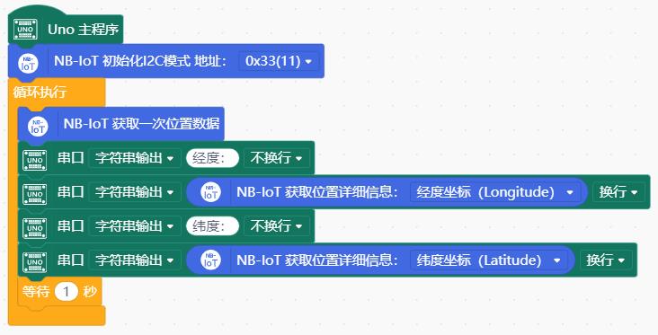
8.4 样例代码(Mind+)
安装Mind+用户库
- 打开Mind+,在扩展中选择Arduino UNO主控板。
- 在扩展中选择用户库,输入项目网址:https://gitee.com/chenqi1233/ext-BC20_NB-IoT.git ,安装BC20的用户库。
配置通信接口
- 在使用Mind+进行编程时,每段代码开头都需要有下面一段用于配置通信接口的积木,配合物理接线可配置I2C、UART(硬件)和UART(软件)串口三种不同的通信接口。若不作任何修改,默认使用I2C接口,地址0x33。
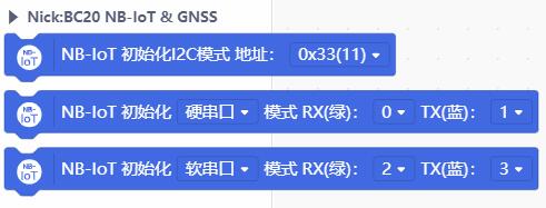
- 使用I2C接口时,若出现IIC地址冲突,可修改下面一条积木中的参数0x33(11)以改变IIC地址。可使用的I2C地址共有4个,拨动模块上的拨码开关,调整A0和A1,并修改如下相应I2C地址,复位程序完成修改。
- 0x30:(A0=0,A1=0)
- 0x31:(A0=0,A1=1)
- 0x32:(A0=1,A1=0)
- 0x33:(A0=1,A1=1) 默认

- 使用UART(硬件)接口时,若使用有多个硬串口的主控板,可以修改下面一条积木中RX(绿)(与模块的接收端相连)和TX(蓝)(与模块的发送端相连)的参数,进行硬串口的I/O口配置。

- 使用UART(软件)接口时,可以修改下面一条积木中RX(绿)和TX(蓝)的参数,进行软串口的I/O口配置。

测量NB-IoT的信号强度
按照连线图,连接好NB-IoT天线,插入SIM卡,并与主控板相连。
将下面样例代码上传至主控板。(默认使用I2C接口,地址0x33。)
打开串口监控器,查看当前信号强度。
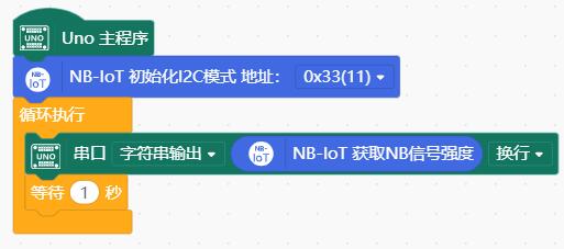
结果
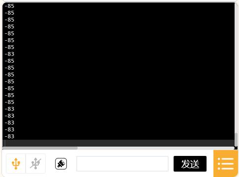
- 程序通过串口打印当前环境(接收到的)NB-IoT信号强度RSSI(单位dBm,通常为负值,测量范围:-113 ~ -51 dBm,数值越大信号越强)。
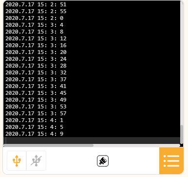
获取日期与时间
按照连线图,连接好NB-IoT天线,插入SIM卡,并与主控板相连。
将下面样例代码上传至主控板。(默认使用I2C接口,地址0x33。)
打开串口监控器,查看当前时间。
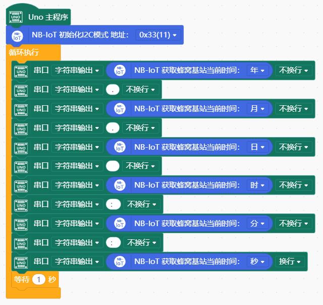
结果
- 程序每隔1s通过串口打印当前地区的日期(年月日)、时间(时分秒)。
- 日期、时间和时区均获取于附近的蜂窝基站,而并非某个网络服务器。
获取物理位置坐标
按照连线图,连接好NB-IoT天线,插入SIM卡,并与主控板相连。
将下面样例代码上传至主控板。(默认使用I2C接口,地址0x33)
打开串口监控器,查看当前地理位置坐标。
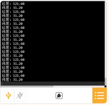
结果
GNSS定位需要一定时间进行寻星,首次上电通常需要30s以上才能获取有效的定位信息。
程序通过串口打印GNSS定位的简单信息:
- 纬度坐标(Latitude):31.20 deg N表示北纬31.20°。南纬用S表示。
- 经度坐标(Longitude):121.60 deg E表示东经121.60°。西经用W表示
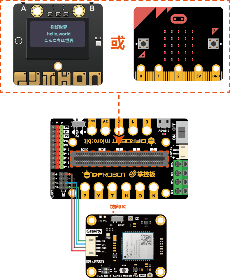
9. 掌控板使用教程
9.1 准备
- 硬件
- 掌控板 x 1
- bit掌控I/O扩展板 x1
- Gravity:I2C & UART BC20 NB-IoT & GNSS通信模块 x 1
- Gravity 4P传感器连接线(或若干杜邦线) x 1
- 软件:
- Mind+图形化编程, 点击下载Mind+
9.2 连线图
如下图,使用I2C接口与掌控板相连,开关拨向I2C一侧。
9.3 样例代码(Mind+)
10. 详细说明
10.1 NB-IoT天线
NB-IoT通信和GNSS定位功能需要外接天线。用户可使用产品包装中所提供的天线,也可额外购买兼容的外接天线以进一步增强收发信号的能力或作为备用。
- 开发板支持B5/B8这两个频段的NB-IoT通信,而目前国内移动、电信、联通三大运营商NB-IoT也主要运行在在这两个频段,具体参数如下:
国内NB-IoT主要运营商与通信频段
| 频段 | 中心频率 | 上行频率 | 下行频率 | 运营商 |
|---|---|---|---|---|
| B5 | 850 MHz | 824 MHz ~ 849 MHz | 869 MHz ~ 894 MHz | 中国电信 |
| B8 | 900MHz | 880 MHz ~ 915 MHz | 925 MHz ~ 960 MHz | 中国移动、中国联通 |
- 用户可使用覆盖B5/B8频段(即工作频率在824MHz~960MHz)的PCB天线(产品附送)、FPC柔性PCB天线、弹簧天线、胶棒天线等各类天线,通常用于2G/GSM/GPRS蜂窝通信的天线也可用于NB-IoT通信(只要工作频率覆盖B5/B8频段),需要注意天线的接头为1代 IPEX接头。
10.2 GNSS天线
- 开发板支持GPS/BeiDou(北斗)双星定位导航,具体参数如下:
GNSS工作频段
| 定位系统 | 接受频段 |
|---|---|
| GPS | L1 C/A 1575.42 MHz |
| BeiDou(北斗) | B1 C/A 1561.098 MHz |
- 用户可使用有源GPS/BeiDou(北斗)双频陶瓷天线,也可使用单频的有源GPS或BeiDou(北斗)陶瓷天线,需要注意天线的接头为1代 IPEX接头。
- 建议使用正方形的右旋圆极化有源陶瓷天线,以便和卫星信号极化匹配,获得更好的信号。陶瓷天线形状为正方形的为右旋圆极化,长方形为线极化。
- 不建议使用无源天线。无源天线需要配合LNA放大器来提高接收信号的强度,而开发板并未搭载LNA放大器。
10.3 SIM卡
NB-IoT通信需要专用的NB-IoT物联网SIM卡,如手机SIM卡,4G物联网卡等其它类型的SIM卡无法代替。目前产品包装内包含有一张中国联通NB-IoT物联网专用SIM卡,包含一份年度基础套餐,插入NB-IoT开发板或通信模组内即可使用,若流量满足不了使用需求,可通过充值月度流量包增加当月流量。后续将会推出更多运营商的NB-IoT物联网专用SIM卡供用户选择。联通NB-IoT SIM卡资费情况如下表:
| 套餐 | 流量 | 有效期 | 资费 | 备注 |
|---|---|---|---|---|
| 年度基础套餐(续费,必需) | 30 MB/月×12=360MB | 360天 | 12元 | 1.有效期自激活之日(首次成功通信)起开始计算,共360天。 2.每30天为一个月度结算周期,每月流量不累计到下个月,超量停机,直到下个月度结算周期或充值月度流量包恢复。 3.360天到期后自动停机,续费年度基础套餐自动恢复开通。 4.有效期结束前续费年度基础套餐,下一年可不停机无缝继续使用。 |
| 月度流量包(可选) | 30M/个 | 30天 | 3元 | 1.有效期自充值当天开始计算 2.随充随用,可无限叠加。 3.仅在年度基础套餐有效期内使用。 |
| NB-IoT物联网专用SIM卡(补卡) | 30 MB/月×12=360MB | 360天 | 15元 | 1.需要联系客服核实信息方可购买,不单独销售。 |
注意
- 根据国家工业和信息化部等六部门要求,为有效防范和打击通讯信息诈骗,所有NB-IoT物联网专用SIM卡均具有机卡绑定功能,不可取消。
- SIM卡插入设备,首次上电(与基站)成功通信即视为激活且与通信模组绑定(机卡绑定),开始年度计费周期(360天)。
- 2G/3G/4G手机SIM卡或大流量物联网卡无法代替用于NB-IoT设备。
- 物联网SIM卡不能用于手机、平板、2G/3G/4G模组等非NB-IoT设备,否则会导致SIM卡停机。
- 已机卡绑定的SIM卡若被插入其它设备内进行通信会导致SIM卡停机。
- 物联网SIM卡仅能数据传输,无语音通信和短信功能。
- 用户可通过微信搜索并关注公众号“DF物联网”,自助查询SIM流量使用情况或对SIM卡进行充值。
11. 应用样例
11.1 使用DFRobot Easy-IoT测试云端通信(Arduino)
通过上面的样例完成NB-IoT信号测试,确认附近有NB-IoT信号后,接下来可测试设备与云端的通信情况。这里以DFRobot出品的轻量级Easy-IoT物联网云平台为样例进行介绍。该平台极大地简化了用户设备上云所需要的大量配置,让创客与入门开发者10分钟内实现设备与云端的连接,尤其适用于物联网通信的快速测试和简单物联网项目的搭建。下面简述测试过程
登录Easy-IoT物联网云平台,点击右上角的注册/登录。
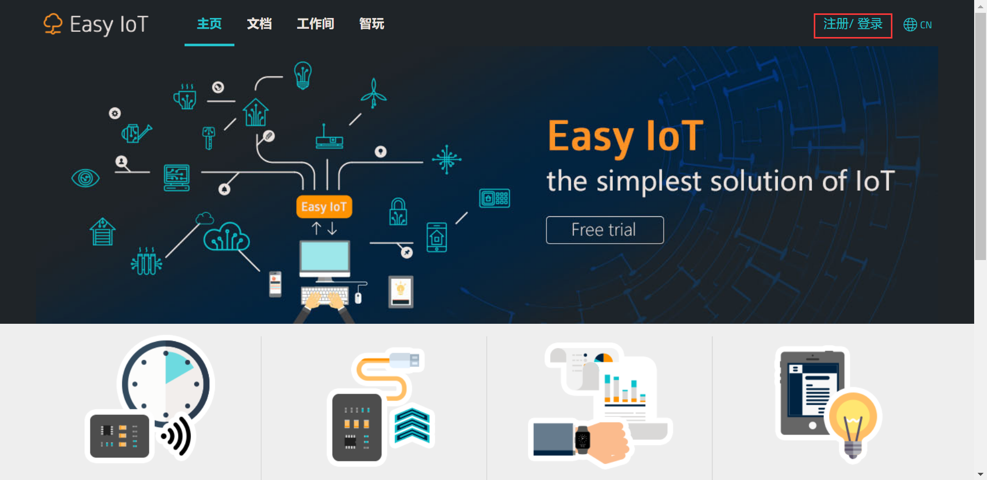
跳转至用户中心页面,按照提示注册新账号或登录现有账号。
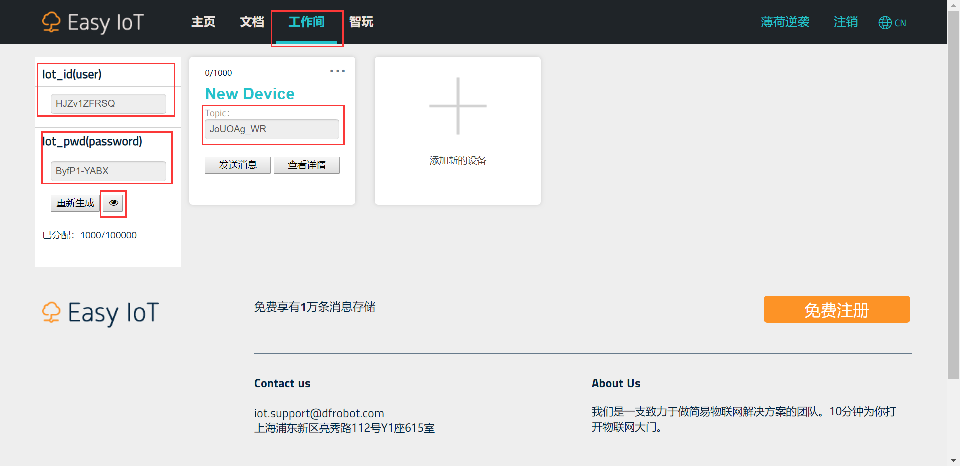
登录后会自动跳转到工作间。首先点击添加新的设备新增随机生成一个Topic。此外注意到左边栏,点击重新生成右边的眼睛按钮,平台已经自动为用户分配随机生成当前账号的Iot_id和Iot_pwd。为了后续让设备与平台正常通信,就需要记录这里的三个参数,填入样例代码中
- Iot_id:HJZv1ZFRSQ
- Iot_pwd:ByfP1-YABX
- Topic:JoUOAg_WR
设备发送消息到云端
- 模块按照连线图与主控板相连,连接好NB-IoT天线,插入SIM卡。
- 将记录下来Iot_id、Iot_pwd和Topic这三个参数的值填入样例代码中,其它参数不变。(Client_ID用于区分不同设备,可任意配置一个数值)
/*Configure device certificate information*/
char* Iot_id = "HJZv1ZFRSQ";        //填入Iot_id
char* Client_ID  = "1234";
char* Iot_pwd    = "ByfP1-YABX";    //填入Iot_pwd

/*Configure the domain name and port number*/
char* EasyIot_SERVER = "182.254.130.180";
char* PORT = "1883";

/*Set the Topic you need to publish to*/
char* pubTopic = "JoUOAg_WR"; //填入Topic- 下面经过修改后的样例代码上传至主控板。(默认使用I2C接口,地址0x33。)
- 打开串口监控器,波特率设为115200。
/*
   @file Publish_Topic.ino

   @brief Connect to DFRobot Easy-IoT cloud platform,
   @brief and publish data to your Topic

   @copyright   Copyright (c) 2010 DFRobot Co.Ltd (http://www.dfrobot.com)
   @licence     The MIT License (MIT)
   @author      [PengKaixing](kaixing.peng@dfrobot.com)
   @version  V1.0
   @date  2019-10-29
   @get from https://www.dfrobot.com
*/

#include <DFRobot_BC20_Gravity.h>

/*7 colors are available*/
#define  RED 0
#define  BLUE 1
#define  GREEN 2
#define  YELLOW 3
#define  PURPLE 4
#define  CYAN 5
#define  WHITE 6

/*Configure device certificate information*/
char* Iot_id = "HJZv1ZFRSQ";        //填入Iot_id
char* Client_ID  = "1234";
char* Iot_pwd    = "ByfP1-YABX";    //填入Iot_pwd

/*Configure the domain name and port number*/
char* EasyIot_SERVER = "182.254.130.180";
char* PORT = "1883";

/*Set the Topic you need to publish to*/
char* pubTopic = "JoUOAg_WR";        //填入Topic

/*Communication by IIC*/
#define USE_IIC

/*Communication by HardwareSerial*/
//#define USE_HSERIAL

/*Communication by SoftwareSerial*/
//#define USE_SSERIAL


/******************IIC******************/
#ifdef USE_IIC
/*
   For general controllers. Communicate by IIC
   Connect Instructions
      Controller     |    Module(BC20)
          SDA        |       D/T
          SCL        |       C/R
          GND        |       GND
       5V or 3V3     |       VCC

   IIC address(A0,A1)
     0x30:(A0=0,A1=0)
     0x31:(A0=0,A1=1)
     0x32:(A0=1,A1=0)
     0x33:(A0=1,A1=1) default
*/
DFRobot_BC20_IIC myBC20(0x33);

/******************HardwareSerial******************/
#elif defined(USE_HSERIAL)
/*
   For MEGA2560/ESP32 HardwareSerial
   Connect Instructions
   esp32      |               MEGA Series    |    Module(BC20)
   IO17       |               D16(RX)        |       D/T
   IO16       |               D17(TX)        |       C/R
   GND        |               GND            |       GND
   5V(USB) or 3V3(battery)  | 5V or 3V3      |       VCC
*/
#if defined(ARDUINO_ESP32_DEV)
HardwareSerial Serial2(2);
DFRobot_BC20_Serial myBC20(&Serial2);//ESP32HardwareSerial
#else
DFRobot_BC20_Serial myBC20(&Serial1);//others
#endif

/******************SoftwareSerial******************/
#elif defined(USE_SSERIAL)
/*
    For Arduino Series SoftwareSerial
    Connect Instructions
        UNO     |    Module(BC20)
      PIN_RXD   |       D/T
      PIN_TXD   |       C/R
        GND     |       GND
     5V or 3V3  |       VCC
*/
#define PIN_TXD   3
#define PIN_RXD   4
SoftwareSerial ss(PIN_RXD, PIN_TXD);
DFRobot_BC20_SW_Serial myBC20(&ss);
#endif

void ConnectCloud() {
  Serial.print("Attempting MQTT connection...");
  myBC20.changeColor(YELLOW);
  while (!myBC20.connected()) {
    Serial.print(".");
    myBC20.LED_ON();
    delay(500);
    myBC20.LED_OFF();
    delay(500);

    if (myBC20.connect(Client_ID, Iot_id, Iot_pwd)) {
      Serial.println("\nConnect Server OK");
    } else {
      /**
         Used to detect the connection between the device and the server
      */
      if (myBC20.getQMTCONN())
        break;
    }
  }
}

void setup() {
  Serial.begin(115200);
  myBC20.LED_OFF();

  /*Initialize BC20*/
  Serial.print("Starting the BC20.Please wait. . . ");
  myBC20.changeColor(RED);
  while (!myBC20.powerOn()) {
    Serial.print(".");
    myBC20.LED_ON();
    delay(500);
    myBC20.LED_OFF();
    delay(500);
  }
  Serial.println("BC20 started successfully!");

  /*Check whether SIM card is inserted*/
  Serial.println("Checking SIM card ...");
  myBC20.changeColor(GREEN);
  while (!myBC20.checkNBCard()) {
    Serial.println("Please insert the NB SIM card !");
    myBC20.LED_ON();
    delay(500);
    myBC20.LED_OFF();
    delay(500);
  }
  Serial.println("SIM card check OK!");

  /*Print IMEI, ICCID and IMSI*/
  myBC20.getGSN(IMEI);
  Serial.print("BC20 IMEI: ");
  Serial.println(sGSN.imei);
  Serial.print("SIM card ICCID:");
  Serial.println(myBC20.getQCCID());
  Serial.print("SIM card IMSI: ");
  Serial.println((char *)myBC20.getIMI());

  /**
     The module will automatically attempt to connect to the network (mobile station).
     Check whether it is connected to the network.
  */
  Serial.println("Connecting network ...");
  myBC20.changeColor(BLUE);
  while (myBC20.getGATT() == 0) {
    Serial.print(".");
    myBC20.LED_ON();
    delay(500);
    myBC20.LED_OFF();
    delay(500);
  }
  Serial.println("Network is connected!");

  Serial.println("Connecting to DFRobot Easy-IoT");

  //Configure IoT Server
  myBC20.setServer(EasyIot_SERVER, PORT);
  Serial.println("Server is available!");
  ConnectCloud();
}

void loop() {
  delay(5000);
  Serial.println("send message to cloud...");
  myBC20.publish(pubTopic, "hello");
  Serial.println("Message is sent.");
}
结果
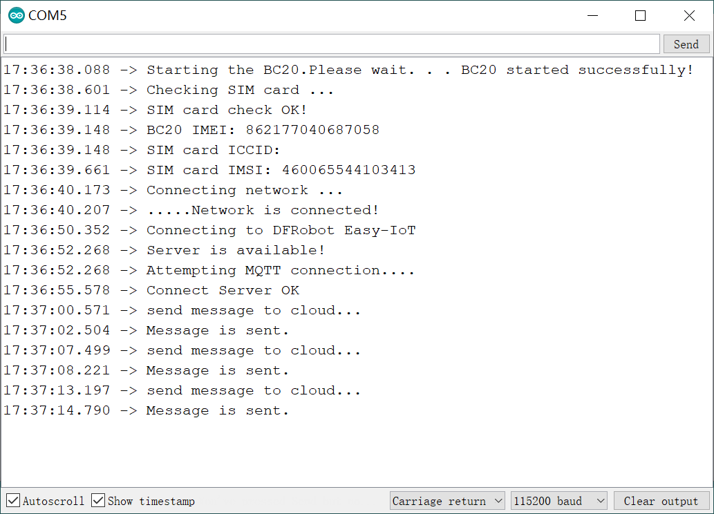
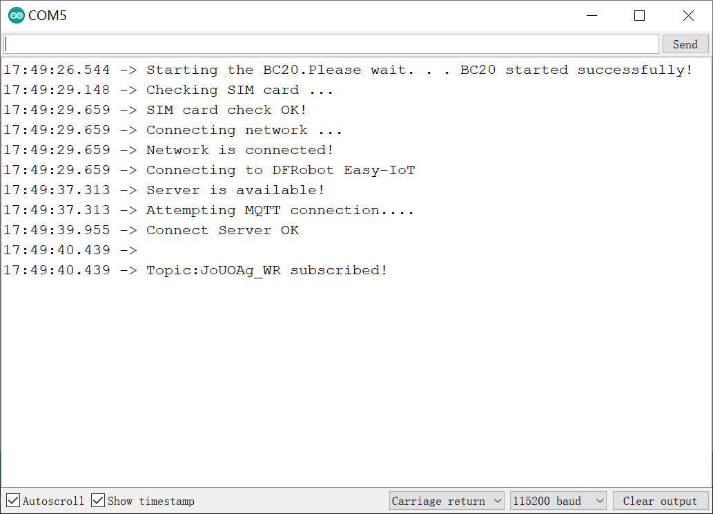
- 串口打印类似于如下信息,表明模块已通过NB-IoT连接上Easy-IoT云平台。程序会每隔5s向Easy-IoT云平台的指定的Topic:JoUOAg_WR,发送一串字符“hello”。每次发送成功会通过串口打印"Message is sent."。
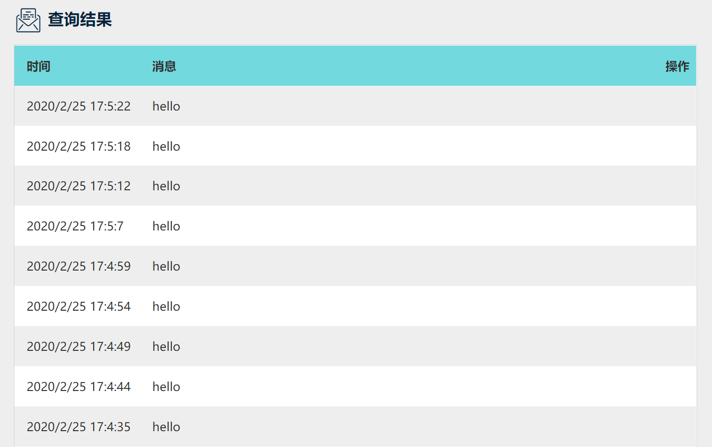
- 为了验证云平台是否确实收到设备端所发送的信息“hello”,回到Easy-IoT云平台的工作间,点击Topic下方的查看详情。
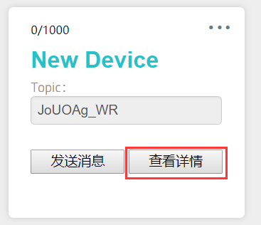
- 在查询结果一栏中可找到云端接收到的消息。
云端发送消息到设备
- 与上一节相同,首先将记录下来Iot_id、Iot_pwd和Topic这三个参数的值分别填入样例代码的Iot_id、Iot_pwd和pubTopic中,其它参数不变。(Client_ID用于区分不同设备,可任意配置一个数值)
/*Configure device certificate information*/
char* Iot_id = "HJZv1ZFRSQ";        //填入Iot_id
char* Client_ID  = "1234";
char* Iot_pwd    = "ByfP1-YABX";    //填入Iot_pwd

/*Configure the domain name and port number*/
char* EasyIot_SERVER = "182.254.130.180";
char* PORT = "1883";

/*Set the Topic you need to publish to*/
char* pubTopic = "JoUOAg_WR"; //填入Topic- 如下,将经过修改后的样例代码上传至主控板。(该样例代码可在Arduino IDE,可以在菜单栏的文件->示例->DFRobot_NBIOT->Default_Run->BC20_MQTT->DFRobot_EasyIoT->Subscribe_Topic中找到该程序。)
- 打开串口监控器,波特率设为115200。
/*!
   @file Subscribe_Topic.ino

   @brief Connect to DFRobot Easy IoT cloud platform,
   @brief and subscribe your Topic

   @copyright   Copyright (c) 2010 DFRobot Co.Ltd (http://www.dfrobot.com)
   @licence     The MIT License (MIT)
   @author      [PengKaixing](kaixing.peng@dfrobot.com)
   @version  V1.0
   @date  2019-10-29
   @get from https://www.dfrobot.com
*/
#include <DFRobot_BC20_Gravity.h>

/*7 colors are available*/
#define  RED 0
#define  BLUE 1
#define  GREEN 2
#define  YELLOW 3
#define  PURPLE 4
#define  CYAN 5
#define  WHITE 6

/*Configure device certificate information*/
char* Iot_id = "HJZv1ZFRSQ";        //填入Iot_id
char* Client_ID  = "1234";
char* Iot_pwd    = "ByfP1-YABX";    //填入Iot_pwd

/*Configure the domain name and port number*/
char* EasyIot_SERVER = "182.254.130.180";
char* PORT = "1883";

/*Set the Topic you need to publish to*/
char* pubTopic = "JoUOAg_WR";        //填入Topic

/*Communication by IIC*/
#define USE_IIC

/*Communication by HardwareSerial*/
//#define USE_HSERIAL

/*Communication by SoftwareSerial*/
//#define USE_SSERIAL


/******************IIC******************/
#ifdef USE_IIC
/*
   For general controllers. Communicate by IIC
   Connect Instructions
      Controller     |    Module(BC20)
          SDA        |       D/T
          SCL        |       C/R
          GND        |       GND
       5V or 3V3     |       VCC

   IIC address(A0,A1)
     0x30:(A0=0,A1=0)
     0x31:(A0=0,A1=1)
     0x32:(A0=1,A1=0)
     0x33:(A0=1,A1=1) default
*/
DFRobot_BC20_IIC myBC20(0x33);

/******************HardwareSerial******************/
#elif defined(USE_HSERIAL)
/*
   For MEGA2560/ESP32 HardwareSerial
   Connect Instructions
   esp32      |               MEGA Series    |    Module(BC20)
   IO16       |               D17(RX)        |       D/T
   IO17       |               D16(TX)        |       C/R
   GND        |               GND            |       GND
   5V(USB) or 3V3(battery)  | 5V or 3V3      |       VCC
*/
#if defined(ARDUINO_ESP32_DEV)
HardwareSerial Serial2(2);
DFRobot_BC20_Serial myBC20(&Serial2);//ESP32HardwareSerial
#else
DFRobot_BC20_Serial myBC20(&Serial2);//others
#endif

/******************SoftwareSerial******************/
#elif defined(USE_SSERIAL)
/*
    For Arduino Series SoftwareSerial
    Connect Instructions
        UNO     |    Module(BC20)
      PIN_RXD   |       D/T
      PIN_TXD   |       C/R
        GND     |       GND
     5V or 3V3  |       VCC
*/
#define PIN_TXD   3
#define PIN_RXD   4
SoftwareSerial ss(PIN_RXD,PIN_TXD);
DFRobot_BC20_SW_Serial myBC20(&ss);
#endif

/*
  Callback function.
  This will be called when message is received from the subscribed topic.
*/
void callback(char * topic, uint8_t * payload, unsigned int len) {
  Serial.print("Recevice [Topic:");
  Serial.print(topic);
  Serial.print("] ");
  for (int i = 0; i < len; i++) {
    Serial.print((char)payload[i]);
  }
  Serial.println();

  //Control onboard RGB LED according to received message.
  String receivedData = payload;
  if (receivedData.equals("OFF") == true) {
    myBC20.LED_OFF();
    //    Serial.println("LED is OFF.");
  }
  else if (receivedData.equals("RED") == true) {
    myBC20.changeColor(RED);
    myBC20.LED_ON();
    //    Serial.println("LED is red.");
  }
  else if (receivedData.equals("GREEN") == true) {
    myBC20.changeColor(GREEN);
    myBC20.LED_ON();
    //      Serial.println("LED is green.");
  }
  else if (receivedData.equals("BLUE") == true) {
    myBC20.changeColor(BLUE);
    myBC20.LED_ON();
    //      Serial.println("LED is blue.");
  }
  else if (receivedData.equals("YELLOW") == true) {
    myBC20.changeColor(YELLOW);
    myBC20.LED_ON();
    //      Serial.println("LED is yellow.");
  }
  else if (receivedData.equals("PURPLE") == true) {
    myBC20.changeColor(PURPLE);
    myBC20.LED_ON();
    //      Serial.println("LED is purple.");
  }
  else if (receivedData.equals("CYAN") == true) {
    myBC20.changeColor(CYAN);
    myBC20.LED_ON();
    //      Serial.println("LED is cyan.");
  }
  else if (receivedData.equals("WHITE") == true) {
    myBC20.changeColor(WHITE);
    myBC20.LED_ON();
    //      Serial.println("LED is white.");
  }
  else {
    ;
  }
}

void ConnectCloud() {
  Serial.print("Attempting MQTT connection...");
  while (!myBC20.connected()) {
    Serial.print(".");
    if (myBC20.connect(Client_ID, Iot_id, Iot_pwd)) {
      Serial.println("\nConnect Server OK");
    } else {
      /**
         Used to detect the connection between the device and the server
      */
      if (myBC20.getQMTCONN())
        break;
    }
  }

  while (!myBC20.subTopic('0', '1', subTopic, '0')) {
    Serial.print(".");
  }
  Serial.print("\nTopic:");
  Serial.print(subTopic);
  Serial.println(" subscribed!");
}

void setup() {
  Serial.begin(115200);
  myBC20.LED_OFF();

  /*Initialize BC20*/
  Serial.print("Starting the BC20.Please wait. . . ");
  myBC20.changeColor(RED);
  while (!myBC20.powerOn()) {
    Serial.print(".");
    myBC20.LED_ON();
    delay(500);
    myBC20.LED_OFF();
    delay(500);
  }
  Serial.println("started successfully!");

  /*Check whether SIM card is inserted*/
  Serial.print("Checking SIM card ...");
  myBC20.changeColor(GREEN);
  while (!myBC20.checkNBCard()) {
    Serial.print(".");
    myBC20.LED_ON();
    delay(500);
    myBC20.LED_OFF();
    delay(500);
  }
  Serial.println("OK!");

  //Disable sleep mode
  myBC20.configSleepMode(eSleepMode_Disable);
  //Disable PSM
  myBC20.setPSMMode(ePSM_OFF);

  /**
     The module will automatically attempt to connect to the network (mobile station).
     Check whether it is connected to the network.
  */
  Serial.print("Connecting network ...");
  myBC20.changeColor(BLUE);
  while (myBC20.getGATT() == 0) {
    Serial.print(".");
    myBC20.LED_ON();
    delay(500);
    myBC20.LED_OFF();
    delay(500);
  }
  Serial.println("connected!");

  //Set callback function
  myBC20.setCallback(callback);

  Serial.println("Connecting to DFRobot Easy-IoT");

  //Configure IoT Server
  myBC20.setServer(EasyIot_SERVER, PORT);
  Serial.println("Server is available!");

  //Conect to DFRobot Easy-IoT
  ConnectCloud();

}

void loop() {
  myBC20.loop();
}
结果
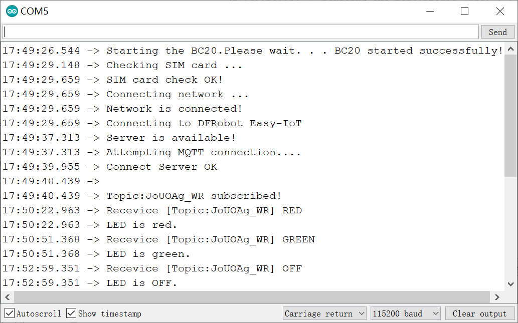
- 串口打印类似于如下信息,表明模块已通过NB-IoT连接上Easy-IoT云平台。
- 在Easy-IoT云平台的工作间,点击Topic下方的发送消息。。
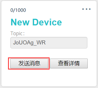
- 在发送新消息输入框中输入需要发送的消息,点击发送向设备端发送消息。每条发送的消息都会记录在下方最新消息中。
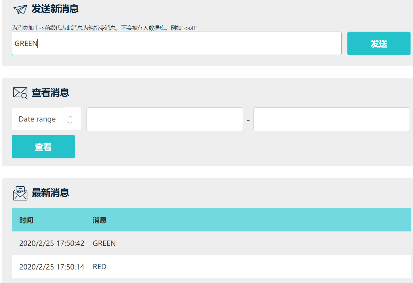
- 为了验证设备是否确实收到消息,回到串口监控器,可发现程序打印出刚才在云端发送的消息内容,并显示消息来自于哪个Topic。
- 此外,当接收到RED,GREEN,BLUE,YELLOW,PURPLE,CYAN,WHITE,OFF这八个消息时,板载RGB LED会分别实现红,绿,蓝,黄,紫,青,白的点亮与关闭
至此,通过上述两个样例,完成了通信模块(设备端)与Easy-IoT云平台(云端)的双向通信测试。
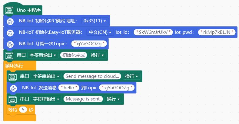
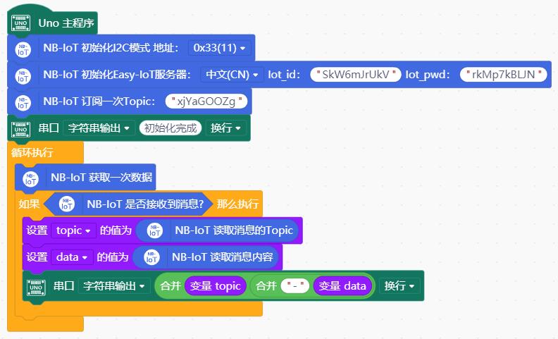
11.2 使用DFRobot Easy-IoT测试云端通信(Mind+)
通过上面的样例完成NB-IoT信号测试,确认附近有NB-IoT信号后,接下来可测试设备与云端的通信情况。这里以DFRobot出品的轻量级Easy-IoT物联网云平台为样例进行介绍。该平台极大地简化了用户设备上云所需要的大量配置,让创客与入门开发者10分钟内实现设备与云端的连接,尤其适用于物联网通信的快速测试和简单物联网项目的搭建。下面简述测试过程
登录Easy-IoT物联网云平台,点击右上角的注册/登录。
跳转至用户中心页面,按照提示注册新账号或登录现有账号。
登录后会自动跳转到工作间。首先点击添加新的设备新增随机生成一个Topic。此外注意到左边栏,点击重新生成右边的眼睛按钮,平台已经自动为用户分配随机生成当前账号的Iot_id和Iot_pwd。为了后续让设备与平台正常通信,就需要记录这里的三个参数,填入样例代码中
- Iot_id
- Iot_pwd
- Topic
设备发送消息到云端
- 模块按照连线图与主控板相连,连接好NB-IoT天线,插入SIM卡。
- 将记录下来Iot_id、Iot_pwd和Topic这三个参数的值填入对应的代码块中。
- 下面经过修改后的样例代码上传至主控板。(默认使用I2C接口,地址0x33。)
- 打开串口监控器。
注意
- 通过NB-IoT向云平台上传数据时,每次上传的时间不建议小于5秒。过于频繁的通过NB-IoT上传数据,可能会被基站短时间内屏蔽。
- NB-IoT在上传数据时,并不能保证可以准时上传,可能会有一定时间的延迟,但不会影响数据内容的上传。这是由于NB-IoT基站的排队机制导致的。
结果
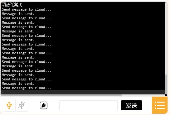
- 串口打印类似于如下信息,表明模块已通过NB-IoT连接上Easy-IoT云平台。程序会每隔5s向Easy-IoT云平台的指定的Topic,发送一串字符“hello”。每次发送成功会通过串口打印"Message is sent."。
- 为了验证云平台是否确实收到设备端所发送的信息“hello”,回到Easy-IoT云平台的工作间,点击Topic下方的查看详情。
- 在查询结果一栏中可找到云端接收到的消息。
云端发送消息到设备
- 首先将记录下来Iot_id、Iot_pwd和Topic这三个参数的值分别填入对应代码块的Iot_id、Iot_pwd和pubTopic中。
- 如下,将经过修改后的样例代码上传至主控板。
- 打开串口监控器。
结果
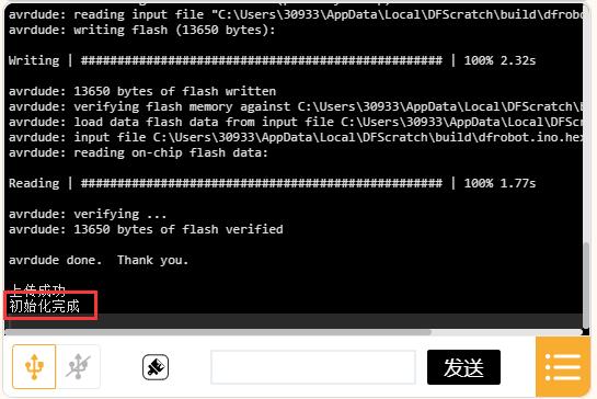
- 串口打印初始化完成,表明模块已通过NB-IoT连接上Easy-IoT云平台。
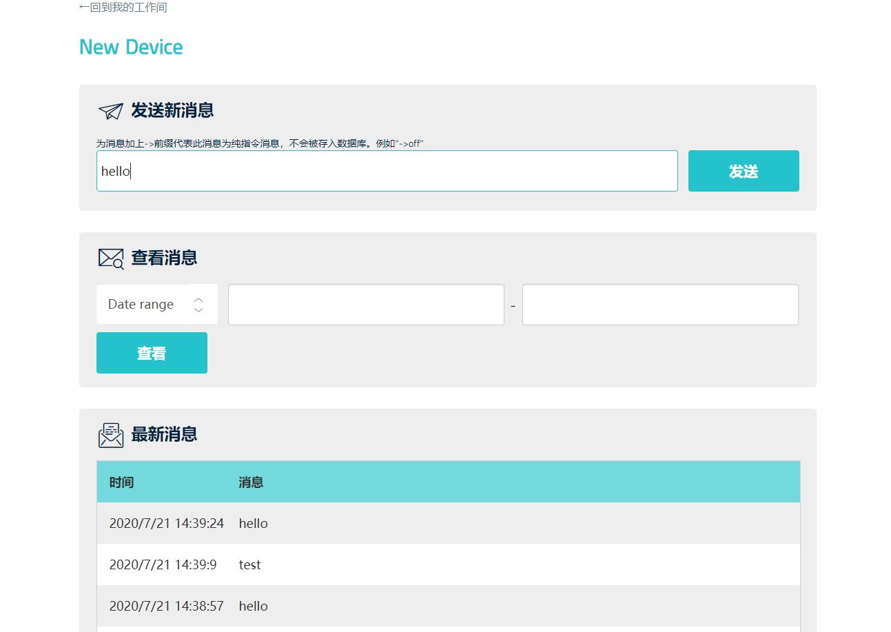
- 在Easy-IoT云平台的工作间,点击Topic下方的发送消息。
- 在发送新消息输入框中输入需要发送的消息,点击发送向设备端发送消息。每条发送的消息都会记录在下方最新消息中。
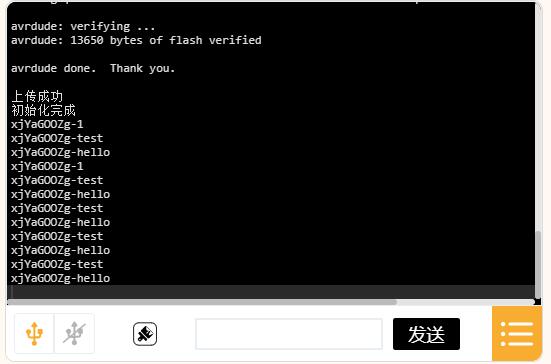
- 为了验证设备是否确实收到消息,回到串口监控器,可发现程序打印出刚才在云端发送的消息内容,并显示消息来自于哪个Topic。
至此,通过上述两个样例,完成了通信模块(设备端)与Easy-IoT云平台(云端)的双向通信测试。
12. 常见问题
Q:uno接bc20,云端通讯为什么串口监视器打印的信息卡在connecting network........?
A:检查天线是否连接。微信公众号DF物联网查看卡的状态。如果同时使用两个库,uno内存可能不够,建议用mega2560,代码同样兼容。
Q:用了发送数据到iot平台的程序之后gnss定位数据就接收不到了?
A:检查上传程序时提示的内存是否不足。
更多问题及有趣的应用,可以 访问论坛 进行查阅或发帖。
