简介
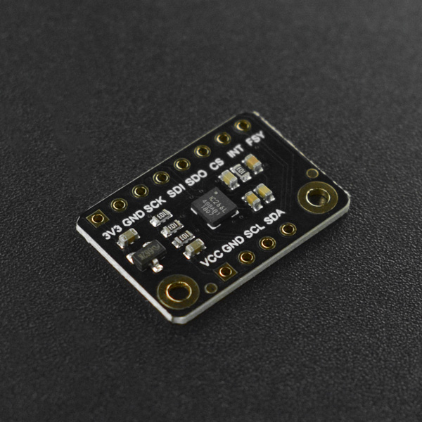
该传感器是一款适合防抖应用的高精度六轴IMU模块,包含3轴加速度(±2/4/8/16g)和3轴陀螺仪(±125/250/500dps),具有16位ADC采样,初始灵敏度均高达±1%,且噪声较低(6.5mdps /√Hz)。此外该传感器还包含一个512字节大的FIFO,可减少串行总线接口上的流量。有可编程中断、帧同步等功能。其中,帧同步功能可以联动其他图像/视频采集设备一起使用,十分适合用于OIS(光学稳定成像)/EIS(电子稳定成像系统)项目中。
特性
- 六轴IMU(3轴加速度+3轴陀螺仪)
- 高性能:高初始灵敏度(均为1%);高精度(16bit ADC);噪声较低(6.5mdps/√Hz)
- 512字节的FIFO
- 功能丰富:外部可编程中断、帧同步、睡眠唤醒、运动检测
应用场景
- 手机相机模块
- 数码单反相机中的图像稳定
- 运动手表
技术规格
- 工作电压:3.3V
- 三轴加速度模式电流消耗:0.52mA
- 三轴陀螺仪模式电流消耗:4.27mA
- 三轴加速度和三轴陀螺仪电流消耗:4.9mA
- 睡眠模式电流消耗:0.14mA
- 集成16位ADC
- 初始灵敏度:加速度±1%,陀螺仪±1%
- 非线性灵敏度:加速度±0.5%,陀螺仪±0.1%
- 接口方式:I2C/SPI(7MHz)
- I2C地址:0x69(默认)/0x68
- 低噪声:6.5mdps /√Hz
- 可选量程:±2g/±4g/±8g/±16g
- 陀螺仪范围:±125/±250/±500 dps
- 数据输出频率:1000~8000 Hz
- 陀螺仪启动时间:80 ms
- 加速度计的启动时间:20ms(从睡眠唤醒)/30ms(初次启动)
- 工作温度范围:-40~+85℃
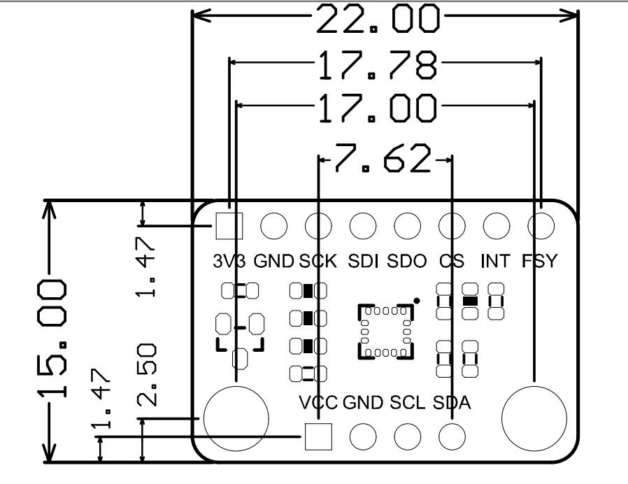
- 模块尺寸:15x22mm
引脚说明
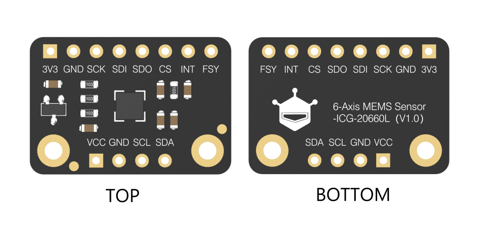
| 序号 | 丝印 | 功能描述 |
|---|---|---|
| 1 | VCC | 3.3V~5V电源输入 |
| 2 | 3V3 | 3.3V电源输入/输出 |
| 3 | GND | GND |
| 4 | SCL | I2C时钟线 |
| 5 | SDA | I2C数据线 |
| 6 | SCK | SPI时钟控制线 |
| 7 | SDI | SPI数据线(输入) |
| 8 | SDO | I2C 地址选择引脚/SPI 数据线(输出) |
| 9 | CS | SPI 片选线 |
| 10 | INT | 中断引脚 |
| 11 | FSY | 同步数字输入(可选) |
*FSY引脚功能:高级用户可将该引脚与其他传感器(例如图像采集模块)结合起来使用以实现整个项目的更好联动,具体的用法请查阅芯片手册
注意:
- 仅支持3.3V主板
- 所有数据输出电压均为3.3V
- I2C连接5V输入会影响传感器的寿命
不同通信方式连线提示:
- I2C:0x69(默认)/ 0x68

- SPI

- demo中的中断引脚连接
| 主板 | 默认连接引脚 |
|---|---|
| Micro:bit | P9 |
| ESP32 | D9 |
| ESP8266 | D5 |
| Raspberry Pi | BCM27 |
- 中断引脚在使用时才进行连接
M0使用教程
准备
- 硬件
- 1 x Firebeetle Board-M0
- 1 x 六轴IMU传感器
- 若干 杜邦线
- 软件
- Arduino IDE, 点击下载Arduino IDE
- 库文件和示例程序
关于如何安装库文件,点击链接
接线图
请按接线图所示将传感器与M0(或其它主板)相连接即可。

-
样例代码
- 主要API接口函数列表
/**
 * @brief The constructor of the ICG20660L sensor, using IIC communication.
 * @param addr:  7-bit IIC address, controlled by SDO pin.
 * @n     IIC_ADDR_SDO_H or 0x69:  SDO pull high.(default)
 * @n     IIC_ADDR_SDO_L or 0x68:  SDO pull down.
 * @param pWire:   TwoWire class pointer.
 */
DFRobot_ICG20660L_IIC(uint8_t addr = IIC_ADDR_SDO_H, TwoWire *pWire = &Wire);

/**
 * @brief The constructor of the ICG20660L sensor, using SPI communication.
 * @param csPin:  SPI chip select pin, connected to IO pin of MCU.
 * @param spi: SPIClass class pointer.
 */
DFRobot_ICG20660L_SPI(int csPin, SPIClass *spi);

/**
 * @brief Initialize the sensor, after initialization, all sensors are turned off, and the corresponding configuration
 * @n needs to be turned on through enableSensor.
 * @param mode: Enum variable,from eDataReadMode_t, configure to read sensor data from FIFO or register?
 * @n     eRegMode: Read sensor data from registers.
 * @n     eFIFOMode:Read sensor data from 512 bytes FIFO. Note: Read from FIFO, accelerometer, gyroscope and temperature must all be enabled,
 * @n and the internal sampling rate must be configured to be consistent.
 * @return status:
 * @n      0 :   Initialization success.
 * @n      -1:   Interface initialization failed(IIC or SPI).
 * @n      -2:   Failed to read the device ID, the ID is not 0x91
 */
int begin(eDataReadMode_t  mode = eRegMode);

/**
 * @brief Get device ID, ICG20660L is 0x91 (145).
 * @return  If device is ICG20660L, it will return 0x91.
 */
uint8_t readID();

/**
 * @brief Enable sensor, including Accel of xyz axis, Gyro of xyz, temperature.
 * @param bit: 8-bit byte data. Each bit represents enabling a function bit, as shown in the following table:
 * @n -------------------------------------------------------------------------------------------------------------------
 * @n |       bit7      |     bit6     |      bit5   |    bit4     |     bit3    |     bit2   |    bit1    |    bit0    |
 * @n -------------------------------------------------------------------------------------------------------------------
 * @n |     reserve     |    reserve   | eAccelAxisX | eAccelAxisY | eAccelAxisZ | eGyroAxisX | eGyroAxisY | eGyroAxisZ |
 * @n |                                |            eAccelAxisXYZ                |           eGyroAxisXYZ               |
 * @n |                                |                                eAxisAll                                        |
 * @n -------------------------------------------------------------------------------------------------------------------
 * @n   bit0:  Z-axis of gyro and temperature.
 * @n   bit1:  Y-axis of gyro and temperature.
 * @n   bit2:  X-axis of gyro and temperature.
 * @n   bit3:  Z-axis of acceleration.
 * @n   bit4:  Z-axis of acceleration.
 * @n   bit5:  Z-axis of acceleration.
 * @n   bit6:  reserve.
 * @n   bit7:  reserve.
 * @n Note: Enabling any axis of the gyroscope will automatically enable the on-board temperature sensor.
 * @n   eGyroAxisZ: The bit0 of the bit, enable gyro's z axis and temperature.
 * @n   eGyroAxisY: The bit1 of the bit, enable gyro's y axis and temperature.
 * @n   eGyroAxisX: The bit2 of the bit, enable gyro's X axis and temperature.
 * @n   eAccelAxisZ: The bit3 of the bit, enable accel's z axis.
 * @n   eAccelAxisY: The bit4 of the bit, enable Accel's y axis.
 * @n   eAccelAxisX: The bit5 of the bit, enable Accel's X axis.
 * @n   eGyroAxisXYZ or eGyroAxisX|eGyroAxisY|eGyroAxisZ: The bit0/bit1/bit2 of the bit, enable gyro's xyz axis and temperature.
 * @n   eAccelAxisXYZ or eAccelAxisX|eAccelAxisY|eAccelAxisZ: The bit3/bit4/bit5 of the bit, enable Accel's xyz axis.
 * @n   eAxisAll or eGyroAxisX|eGyroAxisY|eGyroAxisZ|eAccelAxisX|eAccelAxisY|eAccelAxisZ: The bit0/bit1/bit2/bit3/bit4/bit5 of the bit,
 * @n enable temperature, Accel's and gyro's xyz axis.
 */
void enableSensor(uint8_t bit);

/**
 * @brief Disable sensor, including Accel of xyz axis, Gyro of xyz, temperature.
 * @param bit: 8-bit byte data. Each bit represents enabling a function bit, as shown in the following table:
 * @n -------------------------------------------------------------------------------------------------------------------
 * @n |       bit7      |     bit6     |      bit5   |    bit4     |     bit3    |     bit2   |    bit1    |    bit0    |
 * @n -------------------------------------------------------------------------------------------------------------------
 * @n |     reserve     |    reserve   | eAccelAxisX | eAccelAxisY | eAccelAxisZ | eGyroAxisX | eGyroAxisY | eGyroAxisZ |
 * @n |                                |            eAccelAxisXYZ                |           eGyroAxisXYZ               |
 * @n |                                |                                eAxisAll                                        |
 * @n -------------------------------------------------------------------------------------------------------------------
 * @n   bit0:  Z-axis of gyro and temperature.
 * @n   bit1:  Y-axis of gyro and temperature.
 * @n   bit2:  X-axis of gyro and temperature.
 * @n   bit3:  Z-axis of acceleration.
 * @n   bit4:  Z-axis of acceleration.
 * @n   bit5:  Z-axis of acceleration.
 * @n   bit6:  reserve.
 * @n   bit7:  reserve.
 * @n Note: Only when the X, Y, and Z axes of the gyroscope are all closed, the temperature sensor will be turned off.
 * @n Any axis’s turning on will make the temperature sensor not be turned off.
 * @n   eGyroAxisZ: The bit0 of the bit, disable gyro's z axis.
 * @n   eGyroAxisY: The bit1 of the bit, disable gyro's y axis.
 * @n   eGyroAxisX: The bit2 of the bit, disable gyro's X axis.
 * @n   eAccelAxisZ: The bit3 of the bit, disable accel's z axis.
 * @n   eAccelAxisY: The bit4 of the bit, disable Accel's y axis.
 * @n   eAccelAxisX: The bit5 of the bit, disable Accel's X axis.
 * @n   eGyroAxisXYZ or eGyroAxisX|eGyroAxisY|eGyroAxisZ: The bit0/bit1/bit2 of the bit, disable gyro's xyz axis and temperature.
 * @n   eAccelAxisXYZ or eAccelAxisX|eAccelAxisY|eAccelAxisZ: The bit3/bit4/bit5 of the bit, disable Accel's xyz axis.
 * @n   eAxisAll or eGyroAxisX|eGyroAxisY|eGyroAxisZ|eAccelAxisX|eAccelAxisY|eAccelAxisZ: The bit0/bit1/bit2/bit3/bit4/bit5 of the bit,
 * @n disable temperature, Accel's and gyro's xyz axis.
 */
void disableSensor(uint8_t bit);

/**
 * @brief Config of gyro's full scale, dlpf bandwidth and internal sample rate.
 * @param scale  The full scale of gyro, unit: dps(Degrees per second).
 * @n     eFSR_G_125DPS:  The full scale range is ±125 dps.
 * @n     eFSR_G_250DPS:  The full scale range is ±250 dps.
 * @n     eFSR_G_500DPS:  The full scale range is ±500 dps.
 * @param bd  Set 3-db bandwidth.
 * @n     eGyro_DLPF_8173_32KHZ: When the signal is equal to or greater than 8173Hz, there will be obvious attenuation, 3-db attenuation, and the internal sampling rate is 32KHz.
 * @n     eGyro_DLPF_3281_32KHZ: When the signal is equal to or greater than 3281Hz, there will be obvious attenuation, 3-db attenuation, and the internal sampling rate is 32KHz.
 * @n     eGyro_DLPF_250_8KHZ:   When the signal is equal to or greater than 250Hz, there will be obvious attenuation, 3-db attenuation, and the internal sampling rate is 8KHz.
 * @n     eGyro_DLPF_176_1KHZ:   When the signal is equal to or greater than 176Hz, there will be obvious attenuation, 3-db attenuation, and the internal sampling rate is 1KHz.
 * @n     eGyro_DLPF_92_1KHZ:    When the signal is equal to or greater than 92Hz, there will be obvious attenuation, 3-db attenuation, and the internal sampling rate is 1KHz.
 * @n     eGyro_DLPF_3281_8KHZ:  When the signal is equal to or greater than 3281Hz, there will be obvious attenuation, 3-db attenuation, and the internal sampling rate is 8KHz.
 * @n Note: When the gyroscope and accelerometer are both enabled, if the sensor data is read through the FIFO,
 * @n the internal sampling rate of the gyroscope and accelerometer must be the same.
 */
void configGyro(eGyroFSR_t scale, eGyroBandwidth_t  bd);
void configGyro(uint8_t scale, uint8_t  bd);

/**
 * @brief Config of accel's full scale, dlpf bandwidth and internal sample rate.
 * @param scale  The full scale of accel, unit: g(1g = 9.80665 m/s²).
 * @n     eFSR_A_2G:  The full scale range is ±2g.
 * @n     eFSR_A_4G:  The full scale range is ±4g.
 * @n     eFSR_A_8G:  The full scale range is ±8g.
 * @n     eFSR_A_16G:  The full scale range is ±16g.
 * @param bd  Set 3-db bandwidth.
 * @n     eAccel_DLPF_5_1KHZ or 0:    When the signal is less than or equal to 5Hz, there will be obvious attenuation, 3-db attenuation, and the internal sampling rate is 1KHz.
 * @n     eAccel_DLPF_10_1KHZ or 1:   When the signal is less than or equal to 10Hz, there will be obvious attenuation, 3-db attenuation, and the internal sampling rate is 1KHz.
 * @n     eAccel_DLPF_21_1KHZ or 2:   When the signal is less than or equal to 21Hz, there will be obvious attenuation, 3-db attenuation, and the internal sampling rate is 1KHz.
 * @n     eAccel_DLPF_44_1KHZ or 3:   When the signal is less than or equal to 44Hz, there will be obvious attenuation, 3-db attenuation, and the internal sampling rate is 1KHz.
 * @n     eAccel_DLPF_99_1KHZ or 4:   When the signal is less than or equal to 99Hz, there will be obvious attenuation, 3-db attenuation, and the internal sampling rate is 1KHz.
 * @n     eAccel_DLPF_218_1KHZ or 5:  When the signal is less than or equal to 218Hz, there will be obvious attenuation, 3-db attenuation, and the internal sampling rate is 1KHz.  Support low power consumption mode
 * @n     eAccel_DLPF_420_1KHZ or 6:  When the signal is less than or equal to 420Hz, there will be obvious attenuation, 3-db attenuation, and the internal sampling rate is 1KHz. Support low power consumption mode
 * @n     eAccel_DLPF_1046_4KHZ or 7: When the signal is less than or equal to 1046Hz, there will be obvious attenuation, 3-db attenuation, and the internal sampling rate is 4KHz. Support low power consumption mode
 * @n     eAccel_DLPF_55_1KHZ or 8:   When the signal is less than or equal to 55Hz, there will be obvious attenuation, 3-db attenuation, and the internal sampling rate is 1KHz. Only support low power consumption mode
 * @n     eAccel_DLPF_110_1KHZ or 9:  When the signal is less than or equal to 110Hz, there will be obvious attenuation, 3-db attenuation, and the internal sampling rate is 1KHz.  Only support low power consumption mode
 * @n Note: When the gyroscope and accelerometer are both enabled, if the sensor data is read through the FIFO,
 * @n the internal sampling rate of the gyroscope and accelerometer must be the same.
 * @param odr:  Set the frequency of waking up the chip to take a sample of accel data – the low power accel Output Data Rate.
 * @n     eODR_125Hz or 9:    The low power accel Output Data Rate: 125Hz
 * @n     eODR_250Hz or 10:   The low power accel Output Data Rate: 250Hz
 * @n     eODR_500Hz or 11:   The low power accel Output Data Rate: 500Hz
 * @param lowPowerFlag:  Whether to configure the Acceleration to low power mode.
 * @n     true:          Enter low power mode.
 * @n     false:         Not configure the Acceleration to low power mode.(default)
 */
void configAccel(eAccelFSR_t scale, eAccelBandwidth_t bd, eODR_t odr = eODR_0_24Hz, bool lowPowerFlag = false);
void configAccel(uint8_t scale, uint8_t bd, uint8_t odr = 0, bool lowPowerFlag = false);

/**
 * @brief Set sample rate divider.
 * @param div  Sample rate divider, the range is 0~255.
 * @n     Sampling rate = internal sampling rate/(div+1)
 * @n Note:  If the accelerometer configuration is in low power consumption mode, that is, the formal parameter lowPowerFlag of the configAccel function is true,
 * @n the sampling rate must match the output rate of the formal parameter odr of configAccel, as shown in the following table:
 * @n ----------------------------------------------------------------------------
 * @n |                           configAccel                    |  setSampleDiv  |
 * @n ----------------------------------------------------------------------------|
 * @n |            bd             |      odr      | lowPowerFlag |      div       |
 * @n ----------------------------------------------------------------------------|
 * @n |            X              |       X       |    false     |      0~255     |
 * @n ----------------------------------------------------------------------------|
 * @n |                           |  eODR_125Hz   |    true      |        7       |
 * @n |                           |-----------------------------------------------|
 * @n |bd of supporting low power consumption mode|  eODR_250Hz   |    true      |        3       |
 * @n |                           |-----------------------------------------------|
 * @n |                           |  eODR_500Hz   |    true      |        1       |
 * @n |---------------------------------------------------------------------------|
 */
 void setSampleDiv(uint8_t div);

/**
 * @brief Reset, the register will restore the initial value, and you need to call begin to configuration.
 */
void reset();

/**
 * @brief Entering sleep mode, it will reduce power consumption, and The gyroscope and acceleration will stop working.
 * @n You need to call wakeup function to wake up sensor.
 */
void sleep();

/**
 * @brief Wake up sensor from sleep, and you will restore the configuration before sleep.
 */
void wakeup();

/**
 * @brief Set the level polarity of the INT pin when the accelerometer sensor is triggered to wake up the motion interrupt.
 * @param polarity: the level signal of the sensor INT pin when the wake-up motion is triggered
 * @n     HIGH:The initial signal of the pin is LOW. When an accelerometer wake-up motion occurs, the level signal of the INT pin will change to HIGH.
 * @n Then the readINTStatus function needs to be called to clear the signal and restore the initial signal.
 * @n     LOW: The initial signal of the pin is HIGH. When an accelerometer wake-up motion occurs, the level signal of the INT pin will change to LOW.
 * @n Then the readINTStatus function needs to be called to clear the signal and restore the initial signal.
 * @n Note: After triggering the accelerometer wake-up motion, if the read_int_status function is not called to clear the sign,
 * @n the INT pin will always maintain the level polarity when the motion is triggered.
 */
void setINTPinMotionTriggerPolarity(int polarity);

/**
 * @brief Get the polarity of the INT pin of sensor when the sensor INT pin triggers an interrupt.
 * @return The level signal when the INT pin triggers an interrupt.
 * @n      HIGH:  INT pin level held  HIGH LEVEL until interrupt status is cleared.
 * @n      LOW:   INT pin level held  LOW LEVEL until interrupt status is cleared.
 */
int getINTPinMotionTriggerPolarity();

/**
 * @brief Set the threshold value for the Wake on Motion Interrupt for accelerometer.
 * @param level: WoM thresholds are expressed in fixed “mg” independent of the selected Range [0g : 1g]; Resolution 1g/256=~3.9mg
 * @n     level = 0~255
 * @return Actul WoM thresholds, unit : g   re_value = (level * 3.9)/1000 g
 */
float setWakeOnMotionThresholdForAccel(uint8_t level);

/**
 * @brief Read interrupt status register, and clear INT pin's interrupt signal.
 * @return Interrupt status register value.
 * @n  INT_STATUS register:addr:0x3A,acess:rw
 * @n  ------------------------------------------------------------------------------------
 * @n  |     b7    |    b6     |    b5     |      b4        | b3 | b2 | b1 |      b0      |
 * @n  ------------------------------------------------------------------------------------
 * @n  |             WOM_XYZ_INT           | FIFO_OFLOW_INT |     rsv      | DATA_RDY_INT |
 * @n  ------------------------------------------------------------------------------------
 * @n  DATA_RDY_INT  : This bit automatically sets to 1 when a Data Ready interrupt is generated. The bit clears to 0 after the register has been read.
 * @n  rsv           : reserve
 * @n  FIFO_OFLOW_INT: This bit automatically sets to 1 when a FIFO buffer overflow has been generated. The bit clears to 0 after the register has been read.
 * @n  WOM_XYZ_INT   : These bits automatically set to a non-zero number when the X-axis,Y-axis or Z-axis of accelerometer which trigger WOM(wake on motion)
 * @n                  interrupt.Cleared on Read.
 */
uint8_t readINTStatus();

/**
 * @brief Get Sensor's accel, gyro and temperature data.
 * @param accel: sIcg20660SensorData_t structure pointer which points to accel or NULL.
 * @param gyro: sIcg20660SensorData_t structure pointer which points to gyro or NULL.
 * @param t:  A float pointer which points to temperature or NULL.
 */
void getSensorData(sIcg20660SensorData_t *accel, sIcg20660SensorData_t *gyro, float *t);

/**
 * @brief Get X axis acceleration, unit g.
 * @return  X axis acceleration.
 */
float getAccelDataX();

/**
 * @brief Get Y axis acceleration, unit g.
 * @return  Y axis acceleration.
 */
float getAccelDataY();

/**
 * @brief Get Z axis acceleration, unit g.
 * @return  Z axis acceleration.
 */
float getAccelDataZ();

/**
 * @brief Get temperature data, uint: ℃.
 * @return  Temperature data.
 */
float getTemperatureC();

/**
 * @brief Get X-axis gyroscope speed, unit dps.
 * @return  X-axis gyroscope speed.
 */
float getGyroDataX();

/**
 * @brief Get Y-axis gyroscope speed, unit dps.
 * @return  Y-axis gyroscope speed.
 */
float getGyroDataY();

/**
 * @brief Get Z-axis gyroscope speed, unit dps.
 * @return  Z-axis gyroscope speed.
 */
float getGyroDataZ();

/**
 * @brief Get 14 bytes raw data, including accel, gyro and temperature.
 * @param data:  buffer for storing 14 bytes of raw data.
 * @n     The first byte of data :  Acceleration X-axis high byte data.
 * @n     The second byte of data:  Acceleration X-axis low byte data.
 * @n     The third byte of data :  Acceleration Y-axis high byte data.
 * @n     The 4th byte of data   :  Acceleration Y-axis low byte data.
 * @n     The 5th byte of data   :  Acceleration Z-axis high byte data.
 * @n     The 6th byte of data   :  Acceleration Z-axis low byte data.
 * @n     The 7th byte of data   :  Temperature high byte data.
 * @n     The 8th byte of data   :  Temperature low byte data.
 * @n     The 9th byte of data   :  Gyro X-axis high byte data.
 * @n     The 10th byte of data  :  Gyro X-axis low byte data.
 * @n     The 11th byte of data  :  Gyro Y-axis high byte data.
 * @n     The 12th byte of data  :  Gyro Y-axis low byte data.
 * @n     The 13th byte of data  :  Gyro Z-axis high byte data.
 * @n     The 14th byte of data  :  Gyro Z-axis low byte data.
 * @n Note: You can use RAW_DATA_LENGTH to creat data Arrya, and you can use
 * @n RAW_DATA_AX_H_INDEX, RAW_DATA_AX_L_INDEX, RAW_DATA_AY_H_INDEX, RAW_DATA_AY_L_INDEX, RAW_DATA_AZ_H_INDEX, RAW_DATA_AZ_L_INDEX,
 * @n RAW_DATA_T_H_INDEX, RAW_DATA_T_L_INDEX,RAW_DATA_GX_H_INDEX, RAW_DATA_GX_L_INDEX,
 * @n RAW_DATA_GY_H_INDEX, RAW_DATA_GY_L_INDEX, RAW_DATA_GZ_H_INDEX, RAW_DATA_GZ_L_INDEX or 0~13 to index data array.
 * @param len: The length of data array.
 */
void getRawData(uint8_t *data, uint8_t len = 0);
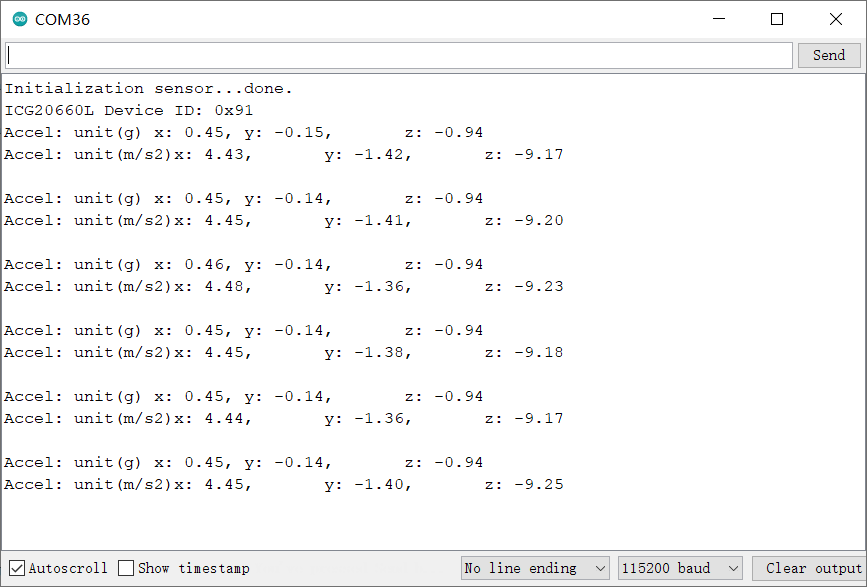
样例代码1-读取x,y,z轴加速度数据(getAccelData.ino)
- 选择getAccelData.ino

- 烧录程序
/*!
 * @file getAccelData.ino
 * @brief 获取传感器的加速度数据,仅适用于寄存器模式(此demo不支持FIFO读取模式)。
 *
 * @n connected table in SPI
 * -----------------------------------------------------------------------------------------------------
 *  sensor pin  |            MCU                    | ESP32 | ESP8266 |    M0   | micro:bit | Mega2560 |
 *    FSY       | not connected, floating           |   X   |    X    |    X    |     X     |     X    |
 *    INT       | not connected, floating           |   X   |    X    |    X    |     X     |     X    |
 *    CS        | connected to the IO pin of MCU    | 5/D8  |  5/D6   |    5    |     P8    |     5    |
 *    SDO       | connected to miso of mcu'spi      |19/MISO|  MISO   |  MISO   |  P14/MISO |  50/MISO |
 *    SDI       | connected to mosi of mcu'spi      |23/MOSI|  MOSI   |  MOSI   |  P15/MOSI |  51/MOSI |
 *    SCK       | connected to sck of mcu'spi       |18/SCK |  SCK    |  SCK    |  P13/SCK  |  52/SCK  |
 *    GND       | GND                               |  GND  |   GND   |   GND   |    GND    |    GND   |
 *    3V3/VCC   | 3V3/VCC                           |  3V3  |   3V3   |   3V3   |    3V3    |    5V    |
 * -----------------------------------------------------------------------------------------------------
 *
 * @n connected table in IIC
 * ---------------------------------------------------------------------------------------------------
 * sensor pin |            MCU                    | ESP32 | ESP8266 |    M0   | micro:bit | Mega2560 |
 *    FSY     | not connected, floating           |   X   |    X    |    X    |     X     |     X    |
 *    INT     | not connected, floating           |   X   |    X    |    X    |     X     |     X    |
 *    SDA     | connected to SDA of mcu'iic       | 21/SDA|   SDA   |   SDA   |  P20/SDA  |  20/SDA  |
 *    SCL     | connected to scl of mcu'iic       | 22/SCL|   SCL   |   SCL   |  P19/SCL  |  21/SCL  |
 *    GND     | GND                               |  GND  |   GND   |   GND   |    GND    |    GND   |
 *    3V3/VCC | 3V3/VCC                           |  3V3  |   3V3   |   3V3   |    3V3    |    5V    |
 * ---------------------------------------------------------------------------------------------------
 *
 * @copyright   Copyright (c) 2010 DFRobot Co.Ltd (http://www.dfrobot.com)
 * @licence     The MIT License (MIT)
 * @author [Arya](xue.peng@dfrobot.com)
 * @version  V1.0
 * @data  2021-05-24
 * @get from https://www.dfrobot.com
 * @url https://github.com/DFRobot/DFRobot_ICG20660L
 */
#include "DFRobot_ICG20660L.h"

#ifdef ARDUINO_BBC_MICROBIT
#define CS_PIN      8                      //The CS pin of sensor which is connected to the 8 digital io pin of micro:bit,and also can connected to other pin.
#else
#define CS_PIN      5                      //The CS pin of sensor which is connected to the 5 digital io pin of MCU,and also can connected to other pin.
#endif
/**
 * @brief The constructor of the ICG20660L sensor using IIC communication.
 * @param addr:  7-bit IIC address, controlled by SDO pin.
 * @n     IIC_ADDR_SDO_H or 0x69:  SDO pull high.(default)
 * @n     IIC_ADDR_SDO_L or 0x68:  SDO pull down.
 * @param pWire:   TwoWire class pointer.
 */
DFRobot_ICG20660L_IIC icg(/*addr=*/IIC_ADDR_SDO_H, &Wire);
/**
 * @brief The constructor of the ICG20660L sensor using SPI communication.
 * @param csPin:  SPI chip select pin, connected to IO pin of MCU.
 * @param spi: SPIClass class pointer.
 */
//DFRobot_ICG20660L_SPI icg(/*csPin=*/CS_PIN, &SPI);

float G = 9.80665; //unit: 1G = 9.80665m/s²
void setup() {
  Serial.begin(115200);
  while(!Serial){                                                     //Waiting for USB Serial COM port to open.
  }

  Serial.print("Initialization sensor...");
/**
 * @brief 初始化传感器,初始化后,所有传感器都被关闭,需通过enableSensor打开相应的配置.
 * @param mode: Enum variable,from eDataReadMode_t,配置读取传感器数据是从FIFO还是从寄存器。
 * @n     eRegMode:  配置为从寄存器读取传感器数据
 * @n     eFIFOMode: 从512字节FIFO读取数据,注意:从FIFO读取,加速度,陀螺仪、温度必须全部使能,且将其内部采样率必须配置成一致。(此demo不支持)
 * @return status:
 * @n      0 :   Initialization sucess.
 * @n      -1:   Interface Initialization failed(IIC or SPI).
 * @n      -2:   读取设备ID失败,ID不是0x91
 */
  while(icg.begin(/*mode=*/icg.eRegMode) != 0){
      Serial.println("failed. Please check whether the hardware connection is wrong.");
      delay(1000);
      Serial.print("Initialization sensor...");
  }
  Serial.println("done.");

  Serial.print("ICG20660L Device ID: 0x");
  Serial.println(icg.readID(), HEX);

/**
 * @brief Enable sensor, Include Accel of xyz axis, Gyro of xyz, temperature.
 * @param bit: 8位字节数据,每一位都代表使能一个功能位,如下表所示:
 * @n -------------------------------------------------------------------------------------------------------------------
 * @n |       bit7      |     bit6     |      bit5   |    bit4     |     bit3    |     bit2   |    bit1    |    bit0    |
 * @n -------------------------------------------------------------------------------------------------------------------
 * @n |     reserve     |    reserve   | eAccelAxisX | eAccelAxisY | eAccelAxisZ | eGyroAxisX | eGyroAxisY | eGyroAxisZ |
 * @n |                                |            eAccelAxisXYZ                |           eGyroAxisXYZ               |
 * @n |                                |                                eAxisAll                                        |
 * @n -------------------------------------------------------------------------------------------------------------------
 * @n   bit0:  Z-axis of gyro and temperature.
 * @n   bit1:  Y-axis of gyro and temperature.
 * @n   bit2:  X-axis of gyro and temperature.
 * @n   bit3:  Z-axis of acceleration.
 * @n   bit4:  Y-axis of acceleration.
 * @n   bit5:  X-axis of acceleration.
 * @n   bit6:  reserve.
 * @n   bit7:  reserve.
 * @n Note: 使能陀螺仪的任意轴,都会自动使能传感器板载温度传感器。
 * @n   eGyroAxisZ: The bit0 of the bit, enable gyro's z axis and temperature.
 * @n   eGyroAxisY: The bit1 of the bit, enable gyro's y axis and temperature.
 * @n   eGyroAxisX: The bit2 of the bit, enable gyro's X axis and temperature.
 * @n   eAccelAxisZ: The bit3 of the bit, enable accel's z axis.
 * @n   eAccelAxisY: The bit4 of the bit, enable Accel's y axis.
 * @n   eAccelAxisX: The bit5 of the bit, enable Accel's X axis.
 * @n   eGyroAxisXYZ or eGyroAxisX|eGyroAxisY|eGyroAxisZ: The bit0/bit1/bit2 of the bit, enable gyro's xyz axis and temperature.
 * @n   eAccelAxisXYZ or eAccelAxisX|eAccelAxisY|eAccelAxisZ: The bit3/bit4/bit5 of the bit, enable Accel's xyz axis.
 * @n   eAxisAll or eGyroAxisX|eGyroAxisY|eGyroAxisZ|eAccelAxisX|eAccelAxisY|eAccelAxisZ: The bit0/bit1/bit2/bit3/bit4/bit5 of the bit, enable temperature, Accel's and gyro's xyz axis.
 */
  icg.enableSensor(icg.eAccelAxisXYZ);
  //icg.enableSensor(icg.eAccelAxisX|icg.eAccelAxisY|icg.eAccelAxisZ);
/**
 * @brief Config of accel's full scale 、dlpf bandwidth and internal sample rate.
 * @param scale  The full scale of accel, unit: g(1g = 9.80665 m/s²).
 * @n     eFSR_A_2G:  The full scale range is ±2g.
 * @n     eFSR_A_4G:  The full scale range is ±4g.
 * @n     eFSR_A_8G:  The full scale range is ±8g.
 * @n     eFSR_A_16G:  The full scale range is ±16g.
 * @param bd  Set 3-db bandwidth.
 * @n     eAccel_DLPF_5_1KHZ or 0:    当信号小于或等于5Hz时,会出现明显衰减,衰减3-db,内部采样率为1KHz
 * @n     eAccel_DLPF_10_1KHZ or 1:   当信号小于或等于10Hz时,会出现明显衰减,衰减3-db,内部采样率为1KHz
 * @n     eAccel_DLPF_21_1KHZ or 2:   当信号小于或等于21Hz时,会出现明显衰减,衰减3-db,内部采样率为1KHz
 * @n     eAccel_DLPF_44_1KHZ or 3:   当信号小于或等于44Hz时,会出现明显衰减,衰减3-db,内部采样率为1KHz
 * @n     eAccel_DLPF_99_1KHZ or 4:   当信号小于或等于99Hz时,会出现明显衰减,衰减3-db,内部采样率为1KHz
 * @n     eAccel_DLPF_218_1KHZ or 5:  当信号小于或等于218Hz时,会出现明显衰减,衰减3-db,内部采样率为1KHz,支持低功耗模式
 * @n     eAccel_DLPF_420_1KHZ or 6:  当信号小于或等于420Hz时,会出现明显衰减,衰减3-db,内部采样率为1KHz,支持低功耗模式
 * @n     eAccel_DLPF_1046_4KHZ or 7: 当信号小于或等于1046Hz时,会出现明显衰减,衰减3-db,内部采样率为4KHz,支持低功耗模式
 * @n     eAccel_DLPF_55_1KHZ or 8:   当信号小于或等于55Hz时,会出现明显衰减,衰减3-db,内部采样率为1KHz,仅支持低功耗模式
 * @n     eAccel_DLPF_110_1KHZ or 9:  当信号小于或等于110Hz时,会出现明显衰减,衰减3-db,内部采样率为1KHz,仅支持低功耗模式
 * @n 注意:当陀螺仪和加速度都使能的时候,如果通过FIFO读取传感器数据,必须保证陀螺仪和加速度的内部采样率一致
 * @param odr:  Sets the frequency of waking up the chip to take a sample of accel data – the low power accel Output Data Rate.
 * @n     eODR_125Hz or 9:    The low power accel Output Data Rate: 125Hz
 * @n     eODR_250Hz or 10:   The low power accel Output Data Rate: 250Hz
 * @n     eODR_500Hz or 11:   The low power accel Output Data Rate: 500Hz
 * @param lowPowerFlag:  Whether to configure the Acceleration to low power mode.
 * @n     true:          Enter low power mode.
 * @n     false:         Not configure the Acceleration to low power mode.(default)
 */
  icg.configAccel(icg.eFSR_A_16G, icg.eAccel_DLPF_99_1KHZ);
/**
 * @brief Set sample rate divider.
 * @param div  Sample rate divider, the range is 0~255.
 * @n     采样率 = 内部采样率/(div+1)
 * @n Note: 如果加速度配置为低功耗模式,即configAccel函数的形参lowPowerFlag为true,则采样率必须和configAccel的形参odr输出率相匹配,如下表所示:
 * @n ----------------------------------------------------------------------------
 * @n |                           configAccel                    |  setSampleDiv  |
 * @n ----------------------------------------------------------------------------|
 * @n |            bd             |      odr      | lowPowerFlag |      div       |
 * @n ----------------------------------------------------------------------------|
 * @n |            X              |       X       |    false     |      0~255     |
 * @n ----------------------------------------------------------------------------|
 * @n |                           |  eODR_125Hz   |    true      |        7       |
 * @n |                           |-----------------------------------------------|
 * @n |  支持低功耗模式的bd       |  eODR_250Hz   |    true      |        3       |
 * @n |                           |-----------------------------------------------|
 * @n |                           |  eODR_500Hz   |    true      |        1       |
 * @n |---------------------------------------------------------------------------|
 */
  icg.setSampleDiv(19);
}

void loop() {
  float x, y, z;
  sIcg20660SensorData_t  accel;
  accel.x = icg.getAccelDataX();
  accel.y = icg.getAccelDataY();
  accel.z = icg.getAccelDataZ();
  Serial.print("Accel: unit(g) ");
  Serial.print("x: ");Serial.print(accel.x);
  Serial.print(",\ty: ");Serial.print(accel.y);
  Serial.print(",\tz: ");Serial.println(accel.z);

  Serial.print("Accel: unit(m/s2)");
  Serial.print("x: ");Serial.print(accel.x*G);
  Serial.print(",\ty: ");Serial.print(accel.y*G);
  Serial.print(",\tz: ");Serial.println(accel.z*G);
  Serial.println();
  delay(1000);
}
- 结果
样例代码2-读取陀螺仪的x,y,z轴的数据(getGyroData.ino)
- 选择getGyroData.ino

- 烧录程序
/*!
 * @file getGyroData.ino
 * @brief 获取传感器的陀螺仪的x,y,z轴的数据(此demo不支持FIFO读取模式),单位dps,并将其转换为角速度rad/s。
 *
 * @n connected table in SPI
 * -----------------------------------------------------------------------------------------------------
 *  sensor pin  |            MCU                    | ESP32 | ESP8266 |    M0   | micro:bit | Mega2560 |
 *    FSY       | not connected, floating           |   X   |    X    |    X    |     X     |     X    |
 *    INT       | not connected, floating           |   X   |    X    |    X    |     X     |     X    |
 *    CS        | connected to the IO pin of MCU    | 5/D8  |  5/D6   |    5    |     P8    |     5    |
 *    SDO       | connected to miso of mcu'spi      |19/MISO|  MISO   |  MISO   |  P14/MISO |  50/MISO |
 *    SDI       | connected to mosi of mcu'spi      |23/MOSI|  MOSI   |  MOSI   |  P15/MOSI |  51/MOSI |
 *    SCK       | connected to sck of mcu'spi       |18/SCK |  SCK    |  SCK    |  P13/SCK  |  52/SCK  |
 *    GND       | GND                               |  GND  |   GND   |   GND   |    GND    |    GND   |
 *    3V3/VCC   | 3V3/VCC                           |  3V3  |   3V3   |   3V3   |    3V3    |    5V    |
 * -----------------------------------------------------------------------------------------------------
 *
 * @n connected table in IIC
 * ---------------------------------------------------------------------------------------------------
 * sensor pin |            MCU                    | ESP32 | ESP8266 |    M0   | micro:bit | Mega2560 |
 *    FSY     | not connected, floating           |   X   |    X    |    X    |     X     |     X    |
 *    INT     | not connected, floating           |   X   |    X    |    X    |     X     |     X    |
 *    SDA     | connected to SDA of mcu'iic       | 21/SDA|   SDA   |   SDA   |  P20/SDA  |  20/SDA  |
 *    SCL     | connected to scl of mcu'iic       | 22/SCL|   SCL   |   SCL   |  P19/SCL  |  21/SCL  |
 *    GND     | GND                               |  GND  |   GND   |   GND   |    GND    |    GND   |
 *    3V3/VCC | 3V3/VCC                           |  3V3  |   3V3   |   3V3   |    3V3    |    5V    |
 * ---------------------------------------------------------------------------------------------------
 *
 * @copyright   Copyright (c) 2010 DFRobot Co.Ltd (http://www.dfrobot.com)
 * @licence     The MIT License (MIT)
 * @author [Arya](xue.peng@dfrobot.com)
 * @version  V1.0
 * @data  2021-05-24
 * @get from https://www.dfrobot.com
 * @url https://github.com/DFRobot/DFRobot_ICG20660L
 */
#include "DFRobot_ICG20660L.h"

#ifdef ARDUINO_BBC_MICROBIT
#define CS_PIN      8                      //The CS pin of sensor which is connected to the 8 digital io pin of micro:bit,and also can connected to other pin.
#else
#define CS_PIN      5                      //The CS pin of sensor which is connected to the 5 digital io pin of MCU,and also can connected to other pin.
#endif
/**
 * @brief The constructor of the ICG20660L sensor using IIC communication.
 * @param addr:  7-bit IIC address, controlled by SDO pin.
 * @n     IIC_ADDR_SDO_H or 0x69:  SDO pull high.(default)
 * @n     IIC_ADDR_SDO_L or 0x68:  SDO pull down.
 * @param pWire:   TwoWire class pointer.
 */
DFRobot_ICG20660L_IIC icg(/*addr=*/IIC_ADDR_SDO_H, &Wire);
/**
 * @brief The constructor of the ICG20660L sensor using SPI communication.
 * @param csPin:  SPI chip select pin, connected to IO pin of MCU.
 * @param spi: SPIClass class pointer.
 */
//DFRobot_ICG20660L_SPI icg(/*csPin=*/CS_PIN, &SPI);

float DPS = 3.1415926/180.0; // unit: 1dps = 3.1415926/180.0rad/s
void setup() {
  Serial.begin(115200);
  while(!Serial){                                                     //Waiting for USB Serial COM port to open.
  }

  Serial.print("Initialization sensor...");
/**
 * @brief 初始化传感器,初始化后,所有传感器都被关闭,需通过enableSensor打开相应的配置.
 * @param mode: Enum variable,from eDataReadMode_t,配置读取传感器数据是从FIFO还是从寄存器。
 * @n     eRegMode:  配置为从寄存器读取传感器数据
 * @n     eFIFOMode: 从512字节FIFO读取数据,注意:从FIFO读取,加速度,陀螺仪、温度必须全部使能,且将其内部采样率必须配置成一致。(此demo不支持)
 * @return status:
 * @n      0 :   Initialization sucess.
 * @n      -1:   Interface Initialization failed(IIC or SPI).
 * @n      -2:   读取设备ID失败,ID不是0x91
 */
  while(icg.begin(/*mode=*/icg.eRegMode) != 0){
      Serial.println("failed. Please check whether the hardware connection is wrong.");
      delay(1000);
      Serial.print("Initialization sensor...");
  }
  Serial.println("done.");

  Serial.print("ICG20660L Device ID: 0x");
  Serial.println(icg.readID(), HEX);

/**
 * @brief Enable sensor, Include Accel of xyz axis, Gyro of xyz, temperature.
 * @param bit: 8位字节数据,每一位都代表使能一个功能位,如下表所示:
 * @n -------------------------------------------------------------------------------------------------------------------
 * @n |       bit7      |     bit6     |      bit5   |    bit4     |     bit3    |     bit2   |    bit1    |    bit0    |
 * @n -------------------------------------------------------------------------------------------------------------------
 * @n |     reserve     |    reserve   | eAccelAxisX | eAccelAxisY | eAccelAxisZ | eGyroAxisX | eGyroAxisY | eGyroAxisZ |
 * @n |                                |            eAccelAxisXYZ                |           eGyroAxisXYZ               |
 * @n |                                |                                eAxisAll                                        |
 * @n -------------------------------------------------------------------------------------------------------------------
 * @n   bit0:  Z-axis of gyro and temperature.
 * @n   bit1:  Y-axis of gyro and temperature.
 * @n   bit2:  X-axis of gyro and temperature.
 * @n   bit3:  Z-axis of acceleration.
 * @n   bit4:  Z-axis of acceleration.
 * @n   bit5:  Z-axis of acceleration.
 * @n   bit6:  reserve.
 * @n   bit7:  reserve.
 * @n Note: 使能陀螺仪的任意轴,都会自动使能传感器板载温度传感器。
 * @n   eGyroAxisZ: The bit0 of the bit, enable gyro's z axis and temperature.
 * @n   eGyroAxisY: The bit1 of the bit, enable gyro's y axis and temperature.
 * @n   eGyroAxisX: The bit2 of the bit, enable gyro's X axis and temperature.
 * @n   eAccelAxisZ: The bit3 of the bit, enable accel's z axis.
 * @n   eAccelAxisY: The bit4 of the bit, enable Accel's y axis.
 * @n   eAccelAxisX: The bit5 of the bit, enable Accel's X axis.
 * @n   eGyroAxisXYZ or eGyroAxisX|eGyroAxisY|eGyroAxisZ: The bit0/bit1/bit2 of the bit, enable gyro's xyz axis and temperature.
 * @n   eAccelAxisXYZ or eAccelAxisX|eAccelAxisY|eAccelAxisZ: The bit3/bit4/bit5 of the bit, enable Accel's xyz axis.
 * @n   eAxisAll or eGyroAxisX|eGyroAxisY|eGyroAxisZ|eAccelAxisX|eAccelAxisY|eAccelAxisZ: The bit0/bit1/bit2/bit3/bit4/bit5 of the bit, enable temperature, Accel's and gyro's xyz axis.
 */
  icg.enableSensor(icg.eGyroAxisXYZ);
  //icg.enableSensor(icg.eGyroAxisX|icg.eGyroAxisY|icg.eGyroAxisZ);
/**
 * @brief Config of gyro's full scale 、dlpf bandwidth and internal sample rate.
 * @param scale  The full scale of gyro, unit: dps(Degrees per second).
 * @n     eFSR_G_125DPS:  The full scale range is ±125 dps.
 * @n     eFSR_G_250DPS:  The full scale range is ±250 dps.
 * @n     eFSR_G_500DPS:  The full scale range is ±500 dps.
 * @param bd  Set 3-db bandwidth.
 * @n     eGyro_DLPF_8173_32KHZ:    当信号等于或大于8173Hz时,会出现明显衰减,衰减3-db,内部采样率为32KHz
 * @n     eGyro_DLPF_3281_32KHZ: 当信号等于或大于3281Hz时,会出现明显衰减,衰减3-db,内部采样率为32KHz
 * @n     eGyro_DLPF_250_8KHZ:     当信号等于或大于250Hz时,会出现明显衰减,衰减3-db,内部采样率为8KHz
 * @n     eGyro_DLPF_176_1KHZ:     当信号等于或大于176Hz时,会出现明显衰减,衰减3-db,内部采样率为1KHz
 * @n     eGyro_DLPF_92_1KHZ:      当信号等于或大于92Hz时,会出现明显衰减,衰减3-db,内部采样率为1KHz
 * @n     eGyro_DLPF_3281_8KHZ:  当信号等于或大于3281Hz时,会出现明显衰减,衰减3-db,内部采样率为8KHz
 * @n 注意:当陀螺仪和加速度都使能的时候,如果通过FIFO读取传感器数据,必须保证陀螺仪和加速度的内部采样率一致
 */
  icg.configGyro(icg.eFSR_G_250DPS, icg.eGyro_DLPF_8173_32KHZ);
/**
 * @brief Set sample rate divider.
 * @param div  Sample rate divider, the range is 0~255.
 * @n     采样率 = 内部采样率/(div+1)
 * @n Note: 如果陀螺仪配置为低功耗模式,即configAccel函数的形参lowPowerFlag为true,则采样率必须和configAccel的形参odr输出率相匹配,如下表所示:
 * @n ----------------------------------------------------------------------------
 * @n |                           configAccel                    |  setSampleDiv  |
 * @n ----------------------------------------------------------------------------|
 * @n |            bd             |      odr      | lowPowerFlag |      div       |
 * @n ----------------------------------------------------------------------------|
 * @n |            X              |       X       |    false     |      0~255     |
 * @n ----------------------------------------------------------------------------|
 * @n |                           |  eODR_125Hz   |    true      |        7       |
 * @n |                           |-----------------------------------------------|
 * @n |  支持低功耗模式的bd       |  eODR_250Hz   |    true      |        3       |
 * @n |                           |-----------------------------------------------|
 * @n |                           |  eODR_500Hz   |    true      |        1       |
 * @n |---------------------------------------------------------------------------|
 */
  icg.setSampleDiv(19);
}

void loop() {
  sIcg20660SensorData_t  gyro;
  float t;
  gyro.x = icg.getGyroDataX();
  gyro.y = icg.getGyroDataY();
  gyro.z = icg.getGyroDataZ();
  t = icg.getTemperatureC();

  Serial.print("Gyro unit(dps): ");
  Serial.print("\tx: ");Serial.print(gyro.x);
  Serial.print(", \ty: ");Serial.print(gyro.y);
  Serial.print(", \tz: ");Serial.println(gyro.z);

  Serial.print("Gyro unit(rad/s): ");
  Serial.print("\tx: ");Serial.print(gyro.x*DPS);
  Serial.print(", \ty: ");Serial.print(gyro.y*DPS);
  Serial.print(", \tz: ");Serial.println(gyro.z*DPS);

  Serial.print("Temperature: \t");
  Serial.print(t);Serial.println("C\n");
  delay(1000);
}
- 结果

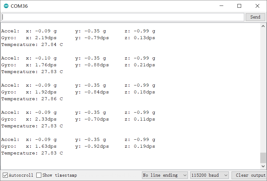
样例代码3-读取陀螺仪、加速度和板载温度数据(getSensorData.ino)
- 选择getSensorData.ino
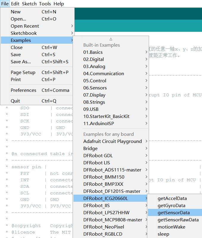
- 烧录程序
/*!
 * @file getSensorData.ino
 * @brief 获取传感器的陀螺仪、加速度和板载温度。
 * @n connected table in SPI
 * -----------------------------------------------------------------------------------------------------
 *  sensor pin  |            MCU                    | ESP32 | ESP8266 |    M0   | micro:bit | Mega2560 |
 *    FSY       | not connected, floating           |   X   |    X    |    X    |     X     |     X    |
 *    INT       | not connected, floating           |   X   |    X    |    X    |     X     |     X    |
 *    CS        | connected to the IO pin of MCU    | 5/D8  |  5/D6   |    5    |     P8    |     5    |
 *    SDO       | connected to miso of mcu'spi      |19/MISO|  MISO   |  MISO   |  P14/MISO |  50/MISO |
 *    SDI       | connected to mosi of mcu'spi      |23/MOSI|  MOSI   |  MOSI   |  P15/MOSI |  51/MOSI |
 *    SCK       | connected to sck of mcu'spi       |18/SCK |  SCK    |  SCK    |  P13/SCK  |  52/SCK  |
 *    GND       | GND                               |  GND  |   GND   |   GND   |    GND    |    GND   |
 *    3V3/VCC   | 3V3/VCC                           |  3V3  |   3V3   |   3V3   |    3V3    |    5V    |
 * -----------------------------------------------------------------------------------------------------
 *
 * @n connected table in IIC
 * ---------------------------------------------------------------------------------------------------
 * sensor pin |            MCU                    | ESP32 | ESP8266 |    M0   | micro:bit | Mega2560 |
 *    FSY     | not connected, floating           |   X   |    X    |    X    |     X     |     X    |
 *    INT     | not connected, floating           |   X   |    X    |    X    |     X     |     X    |
 *    SDA     | connected to SDA of mcu'iic       | 21/SDA|   SDA   |   SDA   |  P20/SDA  |  20/SDA  |
 *    SCL     | connected to scl of mcu'iic       | 22/SCL|   SCL   |   SCL   |  P19/SCL  |  21/SCL  |
 *    GND     | GND                               |  GND  |   GND   |   GND   |    GND    |    GND   |
 *    3V3/VCC | 3V3/VCC                           |  3V3  |   3V3   |   3V3   |    3V3    |    5V    |
 * ---------------------------------------------------------------------------------------------------
 *
 * @copyright   Copyright (c) 2010 DFRobot Co.Ltd (http://www.dfrobot.com)
 * @licence     The MIT License (MIT)
 * @author [Arya](xue.peng@dfrobot.com)
 * @version  V1.0
 * @data  2021-05-24
 * @get from https://www.dfrobot.com
 * @url https://github.com/DFRobot/DFRobot_ICG20660L
 */
#include "DFRobot_ICG20660L.h"

#ifdef ARDUINO_BBC_MICROBIT
#define CS_PIN      8                      //The CS pin of sensor which is connected to the 8 digital io pin of micro:bit,and also can connected to other pin.
#else
#define CS_PIN      5                      //The CS pin of sensor which is connected to the 5 digital io pin of MCU,and also can connected to other pin.
#endif
/**
 * @brief The constructor of the ICG20660L sensor using IIC communication.
 * @param addr:  7-bit IIC address, controlled by SDO pin.
 * @n     IIC_ADDR_SDO_H or 0x69:  SDO pull high.(default)
 * @n     IIC_ADDR_SDO_L or 0x68:  SDO pull down.
 * @param pWire:   TwoWire class pointer.
 */
DFRobot_ICG20660L_IIC icg(/*addr=*/IIC_ADDR_SDO_H, &Wire);
/**
 * @brief The constructor of the ICG20660L sensor using SPI communication.
 * @param csPin:  SPI chip select pin, connected to IO pin of MCU.
 * @param spi: SPIClass class pointer.
 */
//DFRobot_ICG20660L_SPI icg(/*csPin=*/CS_PIN, &SPI);
void setup() {
  Serial.begin(115200);
  while(!Serial){                                                     //Waiting for USB Serial COM port to open.
  }

  Serial.print("Initialization sensor...");
/**
 * @brief 初始化传感器,初始化后,所有传感器都被关闭,需通过enableSensor打开相应的配置.
 * @param mode: Enum variable,from eDataReadMode_t,配置读取传感器数据是从FIFO还是从寄存器。
 * @n     eRegMode:  配置为从寄存器读取传感器数据
 * @n     eFIFOMode: 从512字节FIFO读取数据,注意:从FIFO读取,加速度,陀螺仪、温度必须全部使能,且将其内部采样率必须配置成一致
 * @return status:
 * @n      0 :   Initialization sucess.
 * @n      -1:   Interface Initialization failed(IIC or SPI).
 * @n      -2:   读取设备ID失败,ID不是0x91
 */
  while(icg.begin(/*mode=*/icg.eRegMode) != 0){
      Serial.println("failed. Please check whether the hardware connection is wrong.");
      delay(1000);
      Serial.print("Initialization sensor...");
  }
  Serial.println("done.");

  Serial.print("ICG20660L Device ID: 0x");
  Serial.println(icg.readID(), HEX);

/**
 * @brief Enable sensor, Include Accel of xyz axis, Gyro of xyz, temperature.
 * @param bit: 8位字节数据,每一位都代表使能一个功能位,如下表所示:
 * @n -------------------------------------------------------------------------------------------------------------------
 * @n |       bit7      |     bit6     |      bit5   |    bit4     |     bit3    |     bit2   |    bit1    |    bit0    |
 * @n -------------------------------------------------------------------------------------------------------------------
 * @n |     reserve     |    reserve   | eAccelAxisX | eAccelAxisY | eAccelAxisZ | eGyroAxisX | eGyroAxisY | eGyroAxisZ |
 * @n |                                |            eAccelAxisXYZ                |           eGyroAxisXYZ               |
 * @n |                                |                                eAxisAll                                        |
 * @n -------------------------------------------------------------------------------------------------------------------
 * @n   bit0:  Z-axis of gyro and temperature.
 * @n   bit1:  Y-axis of gyro and temperature.
 * @n   bit2:  X-axis of gyro and temperature.
 * @n   bit3:  Z-axis of acceleration.
 * @n   bit4:  Z-axis of acceleration.
 * @n   bit5:  Z-axis of acceleration.
 * @n   bit6:  reserve.
 * @n   bit7:  reserve.
 * @n Note: 使能陀螺仪的任意轴,都会自动使能传感器板载温度传感器。
 * @n   eGyroAxisZ: The bit0 of the bit, enable gyro's z axis and temperature.
 * @n   eGyroAxisY: The bit1 of the bit, enable gyro's y axis and temperature.
 * @n   eGyroAxisX: The bit2 of the bit, enable gyro's X axis and temperature.
 * @n   eAccelAxisZ: The bit3 of the bit, enable accel's z axis.
 * @n   eAccelAxisY: The bit4 of the bit, enable Accel's y axis.
 * @n   eAccelAxisX: The bit5 of the bit, enable Accel's X axis.
 * @n   eGyroAxisXYZ or eGyroAxisX|eGyroAxisY|eGyroAxisZ: The bit0/bit1/bit2 of the bit, enable gyro's xyz axis and temperature.
 * @n   eAccelAxisXYZ or eAccelAxisX|eAccelAxisY|eAccelAxisZ: The bit3/bit4/bit5 of the bit, enable Accel's xyz axis.
 * @n   eAxisAll or eGyroAxisX|eGyroAxisY|eGyroAxisZ|eAccelAxisX|eAccelAxisY|eAccelAxisZ: The bit0/bit1/bit2/bit3/bit4/bit5 of the bit, enable temperature, Accel's and gyro's xyz axis.
 */
  icg.enableSensor(icg.eAxisAll);
  //icg.enableSensor(icg.eGyroAxisXYZ|icg.eAccelAxisXYZ);
  //icg.enableSensor(icg.eGyroAxisX|icg.eGyroAxisY|icg.eGyroAxisZ|icg.eAccelAxisX|icg.eAccelAxisY|icg.eAccelAxisZ);
/**
 * @brief Config of gyro's full scale 、dlpf bandwidth and internal sample rate.
 * @param scale  The full scale of gyro, unit: dps(Degrees per second).
 * @n     eFSR_G_125DPS:  The full scale range is ±125 dps.
 * @n     eFSR_G_250DPS:  The full scale range is ±250 dps.
 * @n     eFSR_G_500DPS:  The full scale range is ±500 dps.
 * @param bd  Set 3-db bandwidth.
 * @n     eGyro_DLPF_8173_32KHZ:    当信号等于或大于8173Hz时,会出现明显衰减,衰减3-db,内部采样率为32KHz
 * @n     eGyro_DLPF_3281_32KHZ: 当信号等于或大于3281Hz时,会出现明显衰减,衰减3-db,内部采样率为32KHz
 * @n     eGyro_DLPF_250_8KHZ:     当信号等于或大于250Hz时,会出现明显衰减,衰减3-db,内部采样率为8KHz
 * @n     eGyro_DLPF_176_1KHZ:     当信号等于或大于176Hz时,会出现明显衰减,衰减3-db,内部采样率为1KHz
 * @n     eGyro_DLPF_92_1KHZ:      当信号等于或大于92Hz时,会出现明显衰减,衰减3-db,内部采样率为1KHz
 * @n     eGyro_DLPF_3281_8KHZ:  当信号等于或大于3281Hz时,会出现明显衰减,衰减3-db,内部采样率为8KHz
 * @n 注意:当陀螺仪和加速度都使能的时候,如果通过FIFO读取传感器数据,必须保证陀螺仪和加速度的内部采样率一致
 */
  icg.configGyro(/*scale=*/icg.eFSR_G_250DPS, /*bd=*/icg.eGyro_DLPF_176_1KHZ);
/**
 * @brief Config of accel's full scale 、dlpf bandwidth and internal sample rate.
 * @param scale  The full scale of accel, unit: g(1g = 9.80665 m/s²).
 * @n     eFSR_A_2G:  The full scale range is ±2g.
 * @n     eFSR_A_4G:  The full scale range is ±4g.
 * @n     eFSR_A_8G:  The full scale range is ±8g.
 * @n     eFSR_A_16G:  The full scale range is ±16g.
 * @param bd  Set 3-db bandwidth.
 * @n     eAccel_DLPF_5_1KHZ or 0:    当信号小于或等于5Hz时,会出现明显衰减,衰减3-db,内部采样率为1KHz
 * @n     eAccel_DLPF_10_1KHZ or 1:   当信号小于或等于10Hz时,会出现明显衰减,衰减3-db,内部采样率为1KHz
 * @n     eAccel_DLPF_21_1KHZ or 2:   当信号小于或等于21Hz时,会出现明显衰减,衰减3-db,内部采样率为1KHz
 * @n     eAccel_DLPF_44_1KHZ or 3:   当信号小于或等于44Hz时,会出现明显衰减,衰减3-db,内部采样率为1KHz
 * @n     eAccel_DLPF_99_1KHZ or 4:   当信号小于或等于99Hz时,会出现明显衰减,衰减3-db,内部采样率为1KHz
 * @n     eAccel_DLPF_218_1KHZ or 5:  当信号小于或等于218Hz时,会出现明显衰减,衰减3-db,内部采样率为1KHz,支持低功耗模式
 * @n     eAccel_DLPF_420_1KHZ or 6:  当信号小于或等于420Hz时,会出现明显衰减,衰减3-db,内部采样率为1KHz,支持低功耗模式
 * @n     eAccel_DLPF_1046_4KHZ or 7: 当信号小于或等于1046Hz时,会出现明显衰减,衰减3-db,内部采样率为4KHz,支持低功耗模式
 * @n     eAccel_DLPF_55_1KHZ or 8:   当信号小于或等于55Hz时,会出现明显衰减,衰减3-db,内部采样率为1KHz,仅支持低功耗模式
 * @n     eAccel_DLPF_110_1KHZ or 9:  当信号小于或等于110Hz时,会出现明显衰减,衰减3-db,内部采样率为1KHz,仅支持低功耗模式
 * @n 注意:当陀螺仪和加速度都使能的时候,如果通过FIFO读取传感器数据,必须保证陀螺仪和加速度的内部采样率一致
 * @param odr:  Sets the frequency of waking up the chip to take a sample of accel data – the low power accel Output Data Rate.
 * @n     eODR_125Hz or 9:    The low power accel Output Data Rate: 125Hz
 * @n     eODR_250Hz or 10:   The low power accel Output Data Rate: 250Hz
 * @n     eODR_500Hz or 11:   The low power accel Output Data Rate: 500Hz
 * @param lowPowerFlag:  Whether to configure the Acceleration to low power mode.
 * @n     true:          Enter low power mode.
 * @n     false:         Not configure the Acceleration to low power mode.(default)
 */
  icg.configAccel(/*scale=*/icg.eFSR_A_16G, /*bd=*/icg.eAccel_DLPF_218_1KHZ);
/**
 * @brief Set sample rate divider.
 * @param div  Sample rate divider, the range is 0~255.
 * @n     采样率 = 内部采样率/(div+1)
 * @n Note: 如果加速度配置为低功耗模式,即configAccel函数的形参lowPowerFlag为true,则采样率必须和configAccel的形参odr输出率相匹配,如下表所示:
 * @n ----------------------------------------------------------------------------
 * @n |                           configAccel                    |  setSampleDiv  |
 * @n ----------------------------------------------------------------------------|
 * @n |            bd             |      odr      | lowPowerFlag |      div       |
 * @n ----------------------------------------------------------------------------|
 * @n |            X              |       X       |    false     |      0~255     |
 * @n ----------------------------------------------------------------------------|
 * @n |                           |  eODR_125Hz   |    true      |        7       |
 * @n |                           |-----------------------------------------------|
 * @n |  支持低功耗模式的bd       |  eODR_250Hz   |    true      |        3       |
 * @n |                           |-----------------------------------------------|
 * @n |                           |  eODR_500Hz   |    true      |        1       |
 * @n |---------------------------------------------------------------------------|
 */
  icg.setSampleDiv(19);
}

#define printAxisData(sAxis, str) \
  Serial.print(" x: "); \
  Serial.print(sAxis.x); \
  Serial.print(str); \
  Serial.print(" \ty: "); \
  Serial.print(sAxis.y); \
  Serial.print(str); \
  Serial.print(" \tz: "); \
  Serial.print(sAxis.z);\
  Serial.println(str);

void loop() {
  sIcg20660SensorData_t gyro, accel;
  float t;
/**
 * @brief Get Sensor's accel, gyro and temperature data.
 * @param accel: sIcg20660SensorData_t structure pointer which point to accel or NULL.
 * @param gyro: sIcg20660SensorData_t structure pointer which point to gyro or NULL.
 * @param t:  A float pointer which point to temperature or NULL.
 */
  icg.getSensorData(&accel, &gyro, &t);
  Serial.print("Accel: ");printAxisData(accel, " g");
  Serial.print("Gyro:  ");printAxisData(gyro, "dps");
  Serial.print("Temperature: ");Serial.print(t);Serial.println(" C");
  Serial.println();
  delay(1000);
}
- 结果
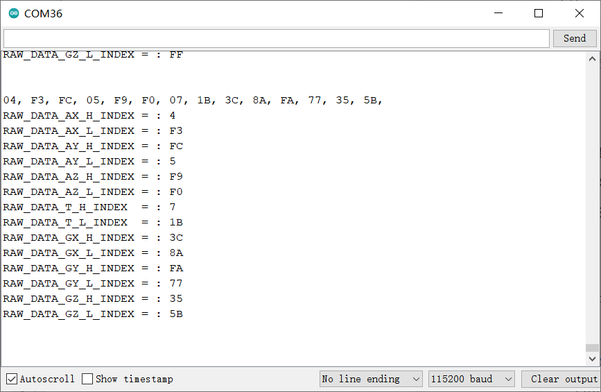
样例代码4-读取加速度,温度、陀螺仪的14字节原始数据(getSensorRawData.ino)
- 选择getSensorRawData.ino
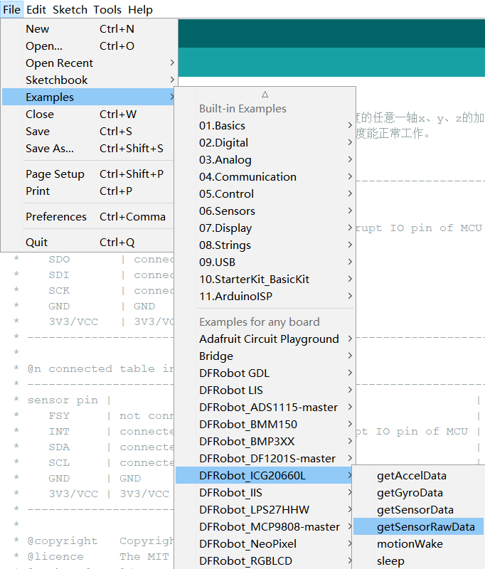
- 烧录程序
/*!
 * @file getSensorRawData.ino
 * @brief 获取14字节原始数据,分别为加速度X、y、z轴数据,温度、陀螺仪X、y、z轴数据
 *
 * @n connected table in SPI
 * -----------------------------------------------------------------------------------------------------
 *  sensor pin  |            MCU                    | ESP32 | ESP8266 |    M0   | micro:bit | Mega2560 |
 *    FSY       | not connected, floating           |   X   |    X    |    X    |     X     |     X    |
 *    INT       | not connected, floating           |   X   |    X    |    X    |     X     |     X    |
 *    CS        | connected to the IO pin of MCU    | 5/D8  |  5/D6   |    5    |     P8    |     5    |
 *    SDO       | connected to miso of mcu'spi      |19/MISO|  MISO   |  MISO   |  P14/MISO |  50/MISO |
 *    SDI       | connected to mosi of mcu'spi      |23/MOSI|  MOSI   |  MOSI   |  P15/MOSI |  51/MOSI |
 *    SCK       | connected to sck of mcu'spi       |18/SCK |  SCK    |  SCK    |  P13/SCK  |  52/SCK  |
 *    GND       | GND                               |  GND  |   GND   |   GND   |    GND    |    GND   |
 *    3V3/VCC   | 3V3/VCC                           |  3V3  |   3V3   |   3V3   |    3V3    |    5V    |
 * -----------------------------------------------------------------------------------------------------
 *
 * @n connected table in IIC
 * ---------------------------------------------------------------------------------------------------
 * sensor pin |            MCU                    | ESP32 | ESP8266 |    M0   | micro:bit | Mega2560 |
 *    FSY     | not connected, floating           |   X   |    X    |    X    |     X     |     X    |
 *    INT     | not connected, floating           |   X   |    X    |    X    |     X     |     X    |
 *    SDA     | connected to SDA of mcu'iic       | 21/SDA|   SDA   |   SDA   |  P20/SDA  |  20/SDA  |
 *    SCL     | connected to scl of mcu'iic       | 22/SCL|   SCL   |   SCL   |  P19/SCL  |  21/SCL  |
 *    GND     | GND                               |  GND  |   GND   |   GND   |    GND    |    GND   |
 *    3V3/VCC | 3V3/VCC                           |  3V3  |   3V3   |   3V3   |    3V3    |    5V    |
 * ---------------------------------------------------------------------------------------------------
 *
 * @copyright   Copyright (c) 2010 DFRobot Co.Ltd (http://www.dfrobot.com)
 * @licence     The MIT License (MIT)
 * @author [Arya](xue.peng@dfrobot.com)
 * @version  V1.0
 * @data  2021-05-24
 * @get from https://www.dfrobot.com
 * @url https://github.com/DFRobot/DFRobot_ICG20660L
 */
#include "DFRobot_ICG20660L.h"

#ifdef ARDUINO_BBC_MICROBIT
#define CS_PIN      8                      //The CS pin of sensor which is connected to the 8 digital io pin of micro:bit,and also can connected to other pin.
#else
#define CS_PIN      5                      //The CS pin of sensor which is connected to the 5 digital io pin of MCU,and also can connected to other pin.
#endif
/**
 * @brief The constructor of the ICG20660L sensor using IIC communication.
 * @param addr:  7-bit IIC address, controlled by SDO pin.
 * @n     IIC_ADDR_SDO_H or 0x69:  SDO pull high.(default)
 * @n     IIC_ADDR_SDO_L or 0x68:  SDO pull down.
 * @param pWire:   TwoWire class pointer.
 */
DFRobot_ICG20660L_IIC icg(/*addr=*/IIC_ADDR_SDO_H, &Wire);
/**
 * @brief The constructor of the ICG20660L sensor using SPI communication.
 * @param csPin:  SPI chip select pin, connected to IO pin of MCU.
 * @param spi: SPIClass class pointer.
 */
//DFRobot_ICG20660L_SPI icg(/*csPin=*/CS_PIN, &SPI);
void setup() {
  Serial.begin(115200);
  while(!Serial){                                                     //Waiting for USB Serial COM port to open.
  }

  Serial.print("Initialization sensor...");
/**
 * @brief 初始化传感器,初始化后,所有传感器都被关闭,需通过enableSensor打开相应的配置.
 * @param mode: Enum variable,from eDataReadMode_t,配置读取传感器数据是从FIFO还是从寄存器。
 * @n     eRegMode:  配置为从寄存器读取传感器数据
 * @n     eFIFOMode: 从512字节FIFO读取数据,注意:从FIFO读取,加速度,陀螺仪、温度必须全部使能,且将其内部采样率必须配置成一致
 * @return status:
 * @n      0 :   Initialization sucess.
 * @n      -1:   Interface Initialization failed(IIC or SPI).
 * @n      -2:   读取设备ID失败,ID不是0x91
 */
  while(icg.begin(/*mode=*/icg.eRegMode) != 0){
      Serial.println("failed. Please check whether the hardware connection is wrong.");
      delay(1000);
      Serial.print("Initialization sensor...");
  }
  Serial.println("done.");

  Serial.print("ICG20660L Device ID: 0x");
  Serial.println(icg.readID(), HEX);

/**
 * @brief Enable sensor, Include Accel of xyz axis, Gyro of xyz, temperature.
 * @param bit: 8位字节数据,每一位都代表使能一个功能位,如下表所示:
 * @n -------------------------------------------------------------------------------------------------------------------
 * @n |       bit7      |     bit6     |      bit5   |    bit4     |     bit3    |     bit2   |    bit1    |    bit0    |
 * @n -------------------------------------------------------------------------------------------------------------------
 * @n |     reserve     |    reserve   | eAccelAxisX | eAccelAxisY | eAccelAxisZ | eGyroAxisX | eGyroAxisY | eGyroAxisZ |
 * @n |                                |            eAccelAxisXYZ                |           eGyroAxisXYZ               |
 * @n |                                |                                eAxisAll                                        |
 * @n -------------------------------------------------------------------------------------------------------------------
 * @n   bit0:  Z-axis of gyro and temperature.
 * @n   bit1:  Y-axis of gyro and temperature.
 * @n   bit2:  X-axis of gyro and temperature.
 * @n   bit3:  Z-axis of acceleration.
 * @n   bit4:  Z-axis of acceleration.
 * @n   bit5:  Z-axis of acceleration.
 * @n   bit6:  reserve.
 * @n   bit7:  reserve.
 * @n Note: 使能陀螺仪的任意轴,都会自动使能传感器板载温度传感器。
 * @n   eGyroAxisZ: The bit0 of the bit, enable gyro's z axis and temperature.
 * @n   eGyroAxisY: The bit1 of the bit, enable gyro's y axis and temperature.
 * @n   eGyroAxisX: The bit2 of the bit, enable gyro's X axis and temperature.
 * @n   eAccelAxisZ: The bit3 of the bit, enable accel's z axis.
 * @n   eAccelAxisY: The bit4 of the bit, enable Accel's y axis.
 * @n   eAccelAxisX: The bit5 of the bit, enable Accel's X axis.
 * @n   eGyroAxisXYZ or eGyroAxisX|eGyroAxisY|eGyroAxisZ: The bit0/bit1/bit2 of the bit, enable gyro's xyz axis and temperature.
 * @n   eAccelAxisXYZ or eAccelAxisX|eAccelAxisY|eAccelAxisZ: The bit3/bit4/bit5 of the bit, enable Accel's xyz axis.
 * @n   eAxisAll or eGyroAxisX|eGyroAxisY|eGyroAxisZ|eAccelAxisX|eAccelAxisY|eAccelAxisZ: The bit0/bit1/bit2/bit3/bit4/bit5 of the bit, enable temperature, Accel's and gyro's xyz axis.
 */
  icg.enableSensor(icg.eAxisAll);
  //icg.enableSensor(icg.eGyroAxisXYZ|icg.eAccelAxisXYZ);
  //icg.enableSensor(icg.eGyroAxisX|icg.eGyroAxisY|icg.eGyroAxisZ|icg.eAccelAxisX|icg.eAccelAxisY|icg.eAccelAxisZ);
/**
 * @brief Config of gyro's full scale 、dlpf bandwidth and internal sample rate.
 * @param scale  The full scale of gyro, unit: dps(Degrees per second).
 * @n     eFSR_G_125DPS:  The full scale range is ±125 dps.
 * @n     eFSR_G_250DPS:  The full scale range is ±250 dps.
 * @n     eFSR_G_500DPS:  The full scale range is ±500 dps.
 * @param bd  Set 3-db bandwidth.
 * @n     eGyro_DLPF_8173_32KHZ:    当信号等于或大于8173Hz时,会出现明显衰减,衰减3-db,内部采样率为32KHz
 * @n     eGyro_DLPF_3281_32KHZ: 当信号等于或大于3281Hz时,会出现明显衰减,衰减3-db,内部采样率为32KHz
 * @n     eGyro_DLPF_250_8KHZ:     当信号等于或大于250Hz时,会出现明显衰减,衰减3-db,内部采样率为8KHz
 * @n     eGyro_DLPF_176_1KHZ:     当信号等于或大于176Hz时,会出现明显衰减,衰减3-db,内部采样率为1KHz
 * @n     eGyro_DLPF_92_1KHZ:      当信号等于或大于92Hz时,会出现明显衰减,衰减3-db,内部采样率为1KHz
 * @n     eGyro_DLPF_3281_8KHZ:  当信号等于或大于3281Hz时,会出现明显衰减,衰减3-db,内部采样率为8KHz
 * @n 注意:当陀螺仪和加速度都使能的时候,如果通过FIFO读取传感器数据,必须保证陀螺仪和加速度的内部采样率一致
 */
  icg.configGyro(/*scale=*/icg.eFSR_G_250DPS, /*bd=*/icg.eGyro_DLPF_176_1KHZ);
/**
 * @brief Config of accel's full scale 、dlpf bandwidth and internal sample rate.
 * @param scale  The full scale of accel, unit: g(1g = 9.80665 m/s²).
 * @n     eFSR_A_2G:  The full scale range is ±2g.
 * @n     eFSR_A_4G:  The full scale range is ±4g.
 * @n     eFSR_A_8G:  The full scale range is ±8g.
 * @n     eFSR_A_16G:  The full scale range is ±16g.
 * @param bd  Set 3-db bandwidth.
 * @n     eAccel_DLPF_5_1KHZ or 0:    当信号小于或等于5Hz时,会出现明显衰减,衰减3-db,内部采样率为1KHz
 * @n     eAccel_DLPF_10_1KHZ or 1:   当信号小于或等于10Hz时,会出现明显衰减,衰减3-db,内部采样率为1KHz
 * @n     eAccel_DLPF_21_1KHZ or 2:   当信号小于或等于21Hz时,会出现明显衰减,衰减3-db,内部采样率为1KHz
 * @n     eAccel_DLPF_44_1KHZ or 3:   当信号小于或等于44Hz时,会出现明显衰减,衰减3-db,内部采样率为1KHz
 * @n     eAccel_DLPF_99_1KHZ or 4:   当信号小于或等于99Hz时,会出现明显衰减,衰减3-db,内部采样率为1KHz
 * @n     eAccel_DLPF_218_1KHZ or 5:  当信号小于或等于218Hz时,会出现明显衰减,衰减3-db,内部采样率为1KHz,支持低功耗模式
 * @n     eAccel_DLPF_420_1KHZ or 6:  当信号小于或等于420Hz时,会出现明显衰减,衰减3-db,内部采样率为1KHz,支持低功耗模式
 * @n     eAccel_DLPF_1046_4KHZ or 7: 当信号小于或等于1046Hz时,会出现明显衰减,衰减3-db,内部采样率为4KHz,支持低功耗模式
 * @n     eAccel_DLPF_55_1KHZ or 8:   当信号小于或等于55Hz时,会出现明显衰减,衰减3-db,内部采样率为1KHz,仅支持低功耗模式
 * @n     eAccel_DLPF_110_1KHZ or 9:  当信号小于或等于110Hz时,会出现明显衰减,衰减3-db,内部采样率为1KHz,仅支持低功耗模式
 * @n 注意:当陀螺仪和加速度都使能的时候,如果通过FIFO读取传感器数据,必须保证陀螺仪和加速度的内部采样率一致
 * @param odr:  Sets the frequency of waking up the chip to take a sample of accel data – the low power accel Output Data Rate.
 * @n     eODR_125Hz or 9:    The low power accel Output Data Rate: 125Hz
 * @n     eODR_250Hz or 10:   The low power accel Output Data Rate: 250Hz
 * @n     eODR_500Hz or 11:   The low power accel Output Data Rate: 500Hz
 * @param lowPowerFlag:  Whether to configure the Acceleration to low power mode.
 * @n     true:          Enter low power mode.
 * @n     false:         Not configure the Acceleration to low power mode.(default)
 */
  icg.configAccel(/*scale=*/icg.eFSR_A_16G, /*bd=*/icg.eAccel_DLPF_218_1KHZ);
/**
 * @brief Set sample rate divider.
 * @param div  Sample rate divider, the range is 0~255.
 * @n     采样率 = 内部采样率/(div+1)
 * @n Note: 如果加速度配置为低功耗模式,即configAccel函数的形参lowPowerFlag为true,则采样率必须和configAccel的形参odr输出率相匹配,如下表所示:
 * @n ----------------------------------------------------------------------------
 * @n |                           configAccel                    |  setSampleDiv  |
 * @n ----------------------------------------------------------------------------|
 * @n |            bd             |      odr      | lowPowerFlag |      div       |
 * @n ----------------------------------------------------------------------------|
 * @n |            X              |       X       |    false     |      0~255     |
 * @n ----------------------------------------------------------------------------|
 * @n |                           |  eODR_125Hz   |    true      |        7       |
 * @n |                           |-----------------------------------------------|
 * @n |  支持低功耗模式的bd       |  eODR_250Hz   |    true      |        3       |
 * @n |                           |-----------------------------------------------|
 * @n |                           |  eODR_500Hz   |    true      |        1       |
 * @n |---------------------------------------------------------------------------|
 */
  icg.setSampleDiv(19);
}

void loop() {
  uint8_t rawData[RAW_DATA_LENGTH];
/**
 * @brief Get 14 bytes raw data, include accel, gyro, and temperature.
 * @param data:  存放14字节原始数据的buffer。
 * @n     The first byte of data :  Acceleration X-axis high byte data.
 * @n     The second byte of data:  Acceleration X-axis low byte data.
 * @n     The third byte of data :  Acceleration Y-axis high byte data.
 * @n     The 4th byte of data   :  Acceleration Y-axis low byte data.
 * @n     The 5th byte of data   :  Acceleration Z-axis high byte data.
 * @n     The 6th byte of data   :  Acceleration Z-axis low byte data.
 * @n     The 7th byte of data   :  Temperature high byte data.
 * @n     The 8th byte of data   :  Temperature low byte data.
 * @n     The 9th byte of data   :  Gyro X-axis high byte data.
 * @n     The 10th byte of data  :  Gyro X-axis low byte data.
 * @n     The 11th byte of data  :  Gyro Y-axis high byte data.
 * @n     The 12th byte of data  :  Gyro Y-axis low byte data.
 * @n     The 13th byte of data  :  Gyro Z-axis high byte data.
 * @n     The 14th byte of data  :  Gyro Z-axis low byte data.
 * @n Note: You can use RAW_DATA_LENGTH to creat data Arrya, and you can use
 * @n RAW_DATA_AX_H_INDEX, RAW_DATA_AX_L_INDEX, RAW_DATA_AY_H_INDEX, RAW_DATA_AY_L_INDEX, RAW_DATA_AZ_H_INDEX, RAW_DATA_AZ_L_INDEX,
 * @n RAW_DATA_T_H_INDEX, RAW_DATA_T_L_INDEX,RAW_DATA_GX_H_INDEX, RAW_DATA_GX_L_INDEX,
 * @n RAW_DATA_GY_H_INDEX, RAW_DATA_GY_L_INDEX, RAW_DATA_GZ_H_INDEX, RAW_DATA_GZ_L_INDEX or 0~13 to index data array.
 * @param len: The length of data array.
 */
  icg.getRawData(rawData,RAW_DATA_LENGTH);
  for(int i = 0; i < RAW_DATA_LENGTH; i++){
      if(rawData[i] < 16){
          Serial.print("0");
      }
      Serial.print(rawData[i],HEX);
      Serial.print(", ");
  }
  Serial.println();
  Serial.print("RAW_DATA_AX_H_INDEX = : ");Serial.println(rawData[RAW_DATA_AX_H_INDEX],HEX);
  Serial.print("RAW_DATA_AX_L_INDEX = : ");Serial.println(rawData[RAW_DATA_AX_L_INDEX],HEX);
  Serial.print("RAW_DATA_AY_H_INDEX = : ");Serial.println(rawData[RAW_DATA_AY_H_INDEX],HEX);
  Serial.print("RAW_DATA_AY_L_INDEX = : ");Serial.println(rawData[RAW_DATA_AY_L_INDEX],HEX);
  Serial.print("RAW_DATA_AZ_H_INDEX = : ");Serial.println(rawData[RAW_DATA_AZ_H_INDEX],HEX);
  Serial.print("RAW_DATA_AZ_L_INDEX = : ");Serial.println(rawData[RAW_DATA_AZ_L_INDEX],HEX);
  Serial.print("RAW_DATA_T_H_INDEX  = : ");Serial.println(rawData[RAW_DATA_T_H_INDEX],HEX);
  Serial.print("RAW_DATA_T_L_INDEX  = : ");Serial.println(rawData[RAW_DATA_T_L_INDEX],HEX);
  Serial.print("RAW_DATA_GX_H_INDEX = : ");Serial.println(rawData[RAW_DATA_GX_H_INDEX],HEX);
  Serial.print("RAW_DATA_GX_L_INDEX = : ");Serial.println(rawData[RAW_DATA_GX_L_INDEX],HEX);
  Serial.print("RAW_DATA_GY_H_INDEX = : ");Serial.println(rawData[RAW_DATA_GY_H_INDEX],HEX);
  Serial.print("RAW_DATA_GY_L_INDEX = : ");Serial.println(rawData[RAW_DATA_GY_L_INDEX],HEX);
  Serial.print("RAW_DATA_GZ_H_INDEX = : ");Serial.println(rawData[RAW_DATA_GZ_H_INDEX],HEX);
  Serial.print("RAW_DATA_GZ_L_INDEX = : ");Serial.println(rawData[RAW_DATA_GZ_L_INDEX],HEX);
  Serial.println('\n');
  delay(1000);
}
- 结果
样例代码5-中断功能(motionWake.ino)
- 选择motionWake.ino
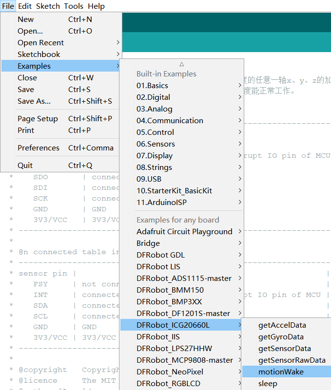
- 烧录程序
/*!
* @file motionWake.ino
* @brief 设置加速度中断唤醒阈值,在低功耗模式下,如果加速度的任意一轴x、y、z的加速度达到此阈值,传感器
* 的中断输出引脚INT将产生一个中断信号。低功耗模式下只有加速度能正常工作。
*
* @n connected table in SPI
* ---------------------------------------------------------------------------------------------------------------------
* Sensor pin | MCU | ESP32 | ESP8266 | M0 | micro:bit | Mega2560 |
* FSY | not connected, floating | X | X | X | X | X |
* INT | connected to the external interrupt IO pin of MCU | 2/D9 | 2/D5 | 2 | P9 | 2 |
* CS | connected to the IO pin of MCU | 5/D8 | 5/D6 | 5 | P8 | 5 |
* SDO | connected to miso of mcu'spi |19/MISO| MISO | MI | P14/MISO | 50/MISO |
* SDI | connected to mosi of mcu'spi |23/MOSI| MOSI | MO | P15/MOSI | 51/MOSI |
* SCK | connected to sck of mcu'spi |18/SCK | SCK | SCK | P13/SCK | 52/SCK |
* GND | GND | GND | GND | GND | GND | GND |
* 3V3/VCC | 3V3/VCC | 3V3 | 3V3 | 3V3 | 3V3 | 5V |
* ---------------------------------------------------------------------------------------------------------------------
*
* @n connected table in IIC
* -------------------------------------------------------------------------------------------------------------------
* sensor pin | MCU | ESP32 | ESP8266 | M0 | micro:bit | Mega2560 |
* FSY | not connected, floating | X | X | X | X | X |
* INT | connected to the external interrupt IO pin of MCU | 2/D9 | 2/D5 | 2 | P9 | 2 |
* SDA | connected to SDA of mcu'iic | 21/SDA| SDA | SDA | P20/SDA | 20/SDA |
* SCL | connected to scl of mcu'iic | 22/SCL| SCL | SCL | P19/SCL | 21/SCL |
* GND | GND | GND | GND | GND | GND | GND |
* 3V3/VCC | 3V3/VCC | 3V3 | 3V3 | 3V3 | 3V3 | 5V |
* -------------------------------------------------------------------------------------------------------------------
*
* @copyright Copyright (c) 2010 DFRobot Co.Ltd (http://www.dfrobot.com)
* @licence The MIT License (MIT)
* @author [Arya](xue.peng@dfrobot.com)
* @version V1.0
* @data 2021-06-01
* @get from https://www.dfrobot.com
* @url https://github.com/DFRobot/DFRobot_ICG20660L
*/
#include "DFRobot_ICG20660L.h"
#if defined(ARDUINO_BBC_MICROBIT)
#define CS_PIN 8 //The CS pin of sensor which is connected to the 8 digital io pin of micro:bit,and also can connected to other pin.
#define INT_PIN 9 //The INT pin of sensor which is connected to the 8 digital io pin of micro:bit,and also can connected to other pin.
#else
#define CS_PIN 5 //The CS pin of sensor which is connected to the 5 digital io pin of MCU,and also can connected to other pin.
#define INT_PIN 2 //The INT pin of sensor which is connected to the 2 digital io pin of MCU,and also can connected to other pin.
#endif
/**
* @brief The constructor of the ICG20660L sensor using IIC communication.
* @param addr: 7-bit IIC address, controlled by SDO pin.
* @n IIC_ADDR_SDO_H or 0x69: SDO pull high.(default)
* @n IIC_ADDR_SDO_L or 0x68: SDO pull down.
* @param pWire: TwoWire class pointer.
*/
DFRobot_ICG20660L_IIC icg(/*addr=*/IIC_ADDR_SDO_H, &Wire);
/**
* @brief The constructor of the ICG20660L sensor using SPI communication.
* @param csPin: SPI chip select pin, connected to IO pin of MCU.
* @param spi: SPIClass class pointer.
*/
//DFRobot_ICG20660L_SPI icg(/*csPin=*/CS_PIN, &SPI);
bool irqFlag = false;
void fun(){
irqFlag = true;
}
void setup() {
Serial.begin(115200);
while(!Serial){ //Waiting for USB Serial COM port to open.
}
Serial.print("Initialization sensor...");
/**
* @brief 初始化传感器,初始化后,所有传感器都被关闭,需通过enableSensor打开相应的配置.
* @param mode: Enum variable,from eDataReadMode_t,配置读取传感器数据是从FIFO还是从寄存器。
* @n eRegMode: 配置为从寄存器读取传感器数据
* @n eFIFOMode: 从512字节FIFO读取数据,注意:从FIFO读取,加速度,陀螺仪、温度必须全部使能,且将其内部采样率必须配置成一致。(此demo不支持)
* @return status:
* @n 0 : Initialization sucess.
* @n -1: Interface Initialization failed(IIC or SPI).
* @n -2: 读取设备ID失败,ID不是0x91
*/
while(icg.begin(/*mode=*/icg.eRegMode) != 0){
Serial.println("failed. Please check whether the hardware connection is wrong.");
delay(1000);
Serial.print("Initialization sensor...");
}
Serial.println("done.");
Serial.print("ICG20660L Device ID: 0x");
Serial.println(icg.readID(), HEX);
/**
* @brief Enable sensor, Include Accel of xyz axis, Gyro of xyz, temperature.
* @param bit: 8位字节数据,每一位都代表使能一个功能位,如下表所示:
* @n -------------------------------------------------------------------------------------------------------------------
* @n | bit7 | bit6 | bit5 | bit4 | bit3 | bit2 | bit1 | bit0 |
* @n -------------------------------------------------------------------------------------------------------------------
* @n | reserve | reserve | eAccelAxisX | eAccelAxisY | eAccelAxisZ | eGyroAxisX | eGyroAxisY | eGyroAxisZ |
* @n | | eAccelAxisXYZ | eGyroAxisXYZ |
* @n | | eAxisAll |
* @n -------------------------------------------------------------------------------------------------------------------
* @n bit0: Z-axis of gyro and temperature.
* @n bit1: Y-axis of gyro and temperature.
* @n bit2: X-axis of gyro and temperature.
* @n bit3: Z-axis of acceleration.
* @n bit4: Z-axis of acceleration.
* @n bit5: Z-axis of acceleration.
* @n bit6: reserve.
* @n bit7: reserve.
* @n Note: 使能陀螺仪的任意轴,都会自动使能传感器板载温度传感器。
* @n eGyroAxisZ: The bit0 of the bit, enable gyro's z axis and temperature.
* @n eGyroAxisY: The bit1 of the bit, enable gyro's y axis and temperature.
* @n eGyroAxisX: The bit2 of the bit, enable gyro's X axis and temperature.
* @n eAccelAxisZ: The bit3 of the bit, enable accel's z axis.
* @n eAccelAxisY: The bit4 of the bit, enable Accel's y axis.
* @n eAccelAxisX: The bit5 of the bit, enable Accel's X axis.
* @n eGyroAxisXYZ or eGyroAxisX|eGyroAxisY|eGyroAxisZ: The bit0/bit1/bit2 of the bit, enable gyro's xyz axis and temperature.
* @n eAccelAxisXYZ or eAccelAxisX|eAccelAxisY|eAccelAxisZ: The bit3/bit4/bit5 of the bit, enable Accel's xyz axis.
* @n eAxisAll or eGyroAxisX|eGyroAxisY|eGyroAxisZ|eAccelAxisX|eAccelAxisY|eAccelAxisZ: The bit0/bit1/bit2/bit3/bit4/bit5 of the bit, enable temperature, Accel's and gyro's xyz axis.
*/
icg.enableSensor(icg.eAccelAxisXYZ);
//icg.enableSensor(icg.eAccelAxisX|icg.eAccelAxisY|icg.eAccelAxisZ);
/**
* @brief Config of accel's full scale 、dlpf bandwidth and internal sample rate.
* @param scale The full scale of accel, unit: g(1g = 9.80665 m/s²).
* @n eFSR_A_2G: The full scale range is ±2g.
* @n eFSR_A_4G: The full scale range is ±4g.
* @n eFSR_A_8G: The full scale range is ±8g.
* @n eFSR_A_16G: The full scale range is ±16g.
* @param bd Set 3-db bandwidth.
* @n eAccel_DLPF_5_1KHZ or 0: 当信号小于或等于5Hz时,会出现明显衰减,衰减3-db,内部采样率为1KHz
* @n eAccel_DLPF_10_1KHZ or 1: 当信号小于或等于10Hz时,会出现明显衰减,衰减3-db,内部采样率为1KHz
* @n eAccel_DLPF_21_1KHZ or 2: 当信号小于或等于21Hz时,会出现明显衰减,衰减3-db,内部采样率为1KHz
* @n eAccel_DLPF_44_1KHZ or 3: 当信号小于或等于44Hz时,会出现明显衰减,衰减3-db,内部采样率为1KHz
* @n eAccel_DLPF_99_1KHZ or 4: 当信号小于或等于99Hz时,会出现明显衰减,衰减3-db,内部采样率为1KHz
* @n eAccel_DLPF_218_1KHZ or 5: 当信号小于或等于218Hz时,会出现明显衰减,衰减3-db,内部采样率为1KHz,支持低功耗模式
* @n eAccel_DLPF_420_1KHZ or 6: 当信号小于或等于420Hz时,会出现明显衰减,衰减3-db,内部采样率为1KHz,支持低功耗模式
* @n eAccel_DLPF_1046_4KHZ or 7: 当信号小于或等于1046Hz时,会出现明显衰减,衰减3-db,内部采样率为4KHz,支持低功耗模式
* @n eAccel_DLPF_55_1KHZ or 8: 当信号小于或等于55Hz时,会出现明显衰减,衰减3-db,内部采样率为1KHz,仅支持低功耗模式
* @n eAccel_DLPF_110_1KHZ or 9: 当信号小于或等于110Hz时,会出现明显衰减,衰减3-db,内部采样率为1KHz,仅支持低功耗模式
* @n 注意:当陀螺仪和加速度都使能的时候,如果通过FIFO读取传感器数据,必须保证陀螺仪和加速度的内部采样率一致
* @param odr: Sets the frequency of waking up the chip to take a sample of accel data – the low power accel Output Data Rate.
* @n eODR_125Hz or 9: The low power accel Output Data Rate: 125Hz
* @n eODR_250Hz or 10: The low power accel Output Data Rate: 250Hz
* @n eODR_500Hz or 11: The low power accel Output Data Rate: 500Hz
* @param lowPowerFlag: Whether to configure the Acceleration to low power mode.
* @n true: Enter low power mode.
* @n false: Not configure the Acceleration to low power mode.(default)
*/
icg.configAccel(icg.eFSR_A_16G, icg.eAccel_DLPF_1046_4KHZ, icg.eODR_500Hz, true);
/**
* @brief Set sample rate divider.
* @param div Sample rate divider, the range is 0~255.
* @n 采样率 = 内部采样率/(div+1)
* @n Note: 如果加速度配置为低功耗模式,即configAccel函数的形参lowPowerFlag为true,则采样率必须和configAccel的形参odr输出率相匹配,如下表所示:
* @n ----------------------------------------------------------------------------
* @n | configAccel | setSampleDiv |
* @n ----------------------------------------------------------------------------|
* @n | bd | odr | lowPowerFlag | div |
* @n ----------------------------------------------------------------------------|
* @n | X | X | false | 0~255 |
* @n ----------------------------------------------------------------------------|
* @n | | eODR_125Hz | true | 7 |
* @n | |-----------------------------------------------|
* @n | 支持低功耗模式的bd | eODR_250Hz | true | 3 |
* @n | |-----------------------------------------------|
* @n | | eODR_500Hz | true | 1 |
* @n |---------------------------------------------------------------------------|
*/
icg.setSampleDiv(1);
/**
* @brief 设置触发加速度传感器唤醒运动中断时,INT引脚的电平极性。
* @param polarity: 触发唤醒运动时,传感器INT引脚的电平信号。
* @n HIGH: INT引脚初始信号为LOW,当产生加速度唤醒运动时,INT引脚电平信号将变为HIGH,需要调用readINTStatus函数,才能清除该信号,重新恢复初始信号。
* @n LOW: INT引脚初始信号为HIGH,当产生加速度唤醒运动时,INT引脚电平信号将变为LOW,需要调用readINTStatus函数,才能清除该信号,重新恢复初始信号。
* @n Note: 触发加速度唤醒运动后,如果不调用readINTStatus函数清除该标志,INT引脚将一直保持触发运动时的电平极性。
*/
icg.setINTPinMotionTriggerPolarity(/*polarity =*/LOW);
/**
* @brief Set the threshold value for the Wake on Motion Interrupt for accelerometer.
* @param level: WoM thresholds are expressed in fixed “mg” independent of the selected Range [0g : 1g]; Resolution 1g/256=~3.9mg
* @n level = 0~255
* @return Actul WoM thresholds, unit : g re_value = (level * 3.9)/1000 g
*/
icg.setWakeOnMotionThresholdForAccel(100);/*rate = 100*3.9/1000 g = 0.39g*/
pinMode(INT_PIN,INPUT);
/**
* @brief Enable the external interrupt pin of MCU.
* @param pin: The external pin of MCU.
* @n Mega2560: The external pin is 2、3、21、20、19、18.
* @n microbit: The external pin is 0~20(P0-P20)
* @n ESP32, ESP8266, M0: The external pin is all digital Pin and analog pin.
* @param fun: Pointer to guide interrupt service function.
* @param mode: Interrupt trigger mode.
* @n LOW: Low level trigger.
* @n HIGH: HIGH level trigger
* @n RISING: Rising edge trigger
* @n FALLING: Falling edge trigger
* @n CHANGE: Double edge transition trigger
*/
attachInterrupt(/*pin=*/digitalPinToInterrupt(INT_PIN),/*fun=*/fun,/*mode =*/FALLING);
}
void loop() {
uint8_t status;
if(irqFlag || (digitalRead(INT_PIN) == icg.getINTPinMotionTriggerPolarity())){
irqFlag = false;
/**
* @brief Read interrupt status register, and clear INT pin's interrupt signal.
* @return Interrupt status register value.
* @n INT_STATUS register:addr:0x3A,acess:rw
* @n ------------------------------------------------------------------------------------
* @n | b7 | b6 | b5 | b4 | b3 | b2 | b1 | b0 |
* @n ------------------------------------------------------------------------------------
* @n | WOM_XYZ_INT | FIFO_OFLOW_INT | rsv | DATA_RDY_INT |
* @n ------------------------------------------------------------------------------------
* @n DATA_RDY_INT : This bit automatically sets to 1 when a Data Ready interrupt is generated. The bit clears to 0 after the register has been read.
* @n rsv : reserve
* @n FIFO_OFLOW_INT: This bit automatically sets to 1 when a FIFO buffer overflow has been generated. The bit clears to 0 after the register has been read.
* @n WOM_XYZ_INT : These bits automatically set to a non-zero number when the X-axis,Y-axis or Z-axis of accelerometer which trigger WOM(wake on motion)
* @n interrupt.Cleared on Read.
*/
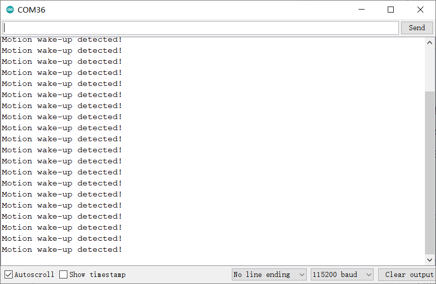
status = icg.readINTStatus();
if(status & ICG20660L_WOM_XYZ_INT){
Serial.println("Motion wake-up detected!");
}else{
Serial.println("Error!");
}
}
}
- 结果
样例代码6-睡眠唤醒功能(sleep.ino)
- 选择sleep.ino
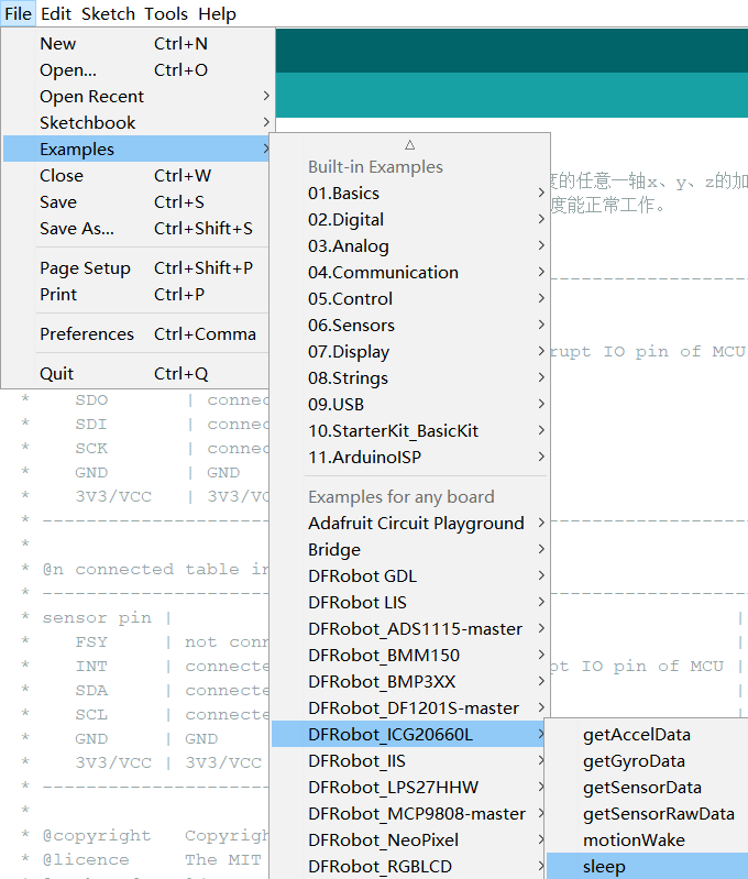
- 烧录程序
/*!
 * @file sleep.ino
 * @brief 采集20次传感器数据后,控制传感器睡眠2s,此时传感器进入低功耗模式,陀螺仪和加速度,将不会工作,再唤醒。
 *
 * @n connected table in SPI
 * -----------------------------------------------------------------------------------------------------
 *  sensor pin  |            MCU                    | ESP32 | ESP8266 |    M0   | micro:bit | Mega2560 |
 *    FSY       | not connected, floating           |   X   |    X    |    X    |     X     |     X    |
 *    INT       | not connected, floating           |   X   |    X    |    X    |     X     |     X    |
 *    CS        | connected to the IO pin of MCU    | 5/D8  |  5/D6   |    5    |     P8    |     5    |
 *    SDO       | connected to miso of mcu'spi      |19/MISO|  MISO   |  MISO   |  P14/MISO |  50/MISO |
 *    SDI       | connected to mosi of mcu'spi      |23/MOSI|  MOSI   |  MOSI   |  P15/MOSI |  51/MOSI |
 *    SCK       | connected to sck of mcu'spi       |18/SCK |  SCK    |  SCK    |  P13/SCK  |  52/SCK  |
 *    GND       | GND                               |  GND  |   GND   |   GND   |    GND    |    GND   |
 *    3V3/VCC   | 3V3/VCC                           |  3V3  |   3V3   |   3V3   |    3V3    |    5V    |
 * -----------------------------------------------------------------------------------------------------
 *
 * @n connected table in IIC
 * ---------------------------------------------------------------------------------------------------
 * sensor pin |            MCU                    | ESP32 | ESP8266 |    M0   | micro:bit | Mega2560 |
 *    FSY     | not connected, floating           |   X   |    X    |    X    |     X     |     X    |
 *    INT     | not connected, floating           |   X   |    X    |    X    |     X     |     X    |
 *    SDA     | connected to SDA of mcu'iic       | 21/SDA|   SDA   |   SDA   |  P20/SDA  |  20/SDA  |
 *    SCL     | connected to scl of mcu'iic       | 22/SCL|   SCL   |   SCL   |  P19/SCL  |  21/SCL  |
 *    GND     | GND                               |  GND  |   GND   |   GND   |    GND    |    GND   |
 *    3V3/VCC | 3V3/VCC                           |  3V3  |   3V3   |   3V3   |    3V3    |    5V    |
 * ---------------------------------------------------------------------------------------------------
 *
 * @copyright   Copyright (c) 2010 DFRobot Co.Ltd (http://www.dfrobot.com)
 * @licence     The MIT License (MIT)
 * @author [Arya](xue.peng@dfrobot.com)
 * @version  V1.0
 * @data  2021-05-24
 * @get from https://www.dfrobot.com
 * @url https://github.com/DFRobot/DFRobot_ICG20660L
 */
#include "DFRobot_ICG20660L.h"

#ifdef ARDUINO_BBC_MICROBIT
#define CS_PIN      8                      //The CS pin of sensor which is connected to the 8 digital io pin of micro:bit,and also can connected to other pin.
#else
#define CS_PIN      5                      //The CS pin of sensor which is connected to the 5 digital io pin of MCU,and also can connected to other pin.
#endif

/**
 * @brief The constructor of the ICG20660L sensor using IIC communication.
 * @param addr:  7-bit IIC address, controlled by SDO pin.
 * @n     IIC_ADDR_SDO_H or 0x69:  SDO pull high.(default)
 * @n     IIC_ADDR_SDO_L or 0x68:  SDO pull down.
 * @param pWire:   TwoWire class pointer.
 */
DFRobot_ICG20660L_IIC icg(/*addr=*/IIC_ADDR_SDO_H, &Wire);
/**
 * @brief The constructor of the ICG20660L sensor using SPI communication.
 * @param csPin:  SPI chip select pin, connected to IO pin of MCU.
 * @param spi: SPIClass class pointer.
 */
//DFRobot_ICG20660L_SPI icg(/*csPin=*/CS_PIN, &SPI);

#define SAMPLE_TIMES    20
uint8_t count = 0;
void setup() {
  Serial.begin(115200);
  while(!Serial){                                                     //Waiting for USB Serial COM port to open.
  }

  Serial.print("Initialization sensor...");
/**
 * @brief 初始化传感器,初始化后,所有传感器都被关闭,需通过enableSensor打开相应的配置.
 * @param mode: Enum variable,from eDataReadMode_t,配置读取传感器数据是从FIFO还是从寄存器。
 * @n     eRegMode:  配置为从寄存器读取传感器数据
 * @n     eFIFOMode: 从512字节FIFO读取数据,注意:从FIFO读取,加速度,陀螺仪、温度必须全部使能,且将其内部采样率必须配置成一致
 * @return status:
 * @n      0 :   Initialization sucess.
 * @n      -1:   Interface Initialization failed(IIC or SPI).
 * @n      -2:   读取设备ID失败,ID不是0x91
 */
  while(icg.begin(/*mode=*/icg.eRegMode) != 0){
      Serial.println("failed. Please check whether the hardware connection is wrong.");
      delay(1000);
      Serial.print("Initialization sensor...");
  }
  Serial.println("done.");

  Serial.print("ICG20660L Device ID: 0x");
  Serial.println(icg.readID(), HEX);

/**
 * @brief Enable sensor, Include Accel of xyz axis, Gyro of xyz, temperature.
 * @param bit: 8位字节数据,每一位都代表使能一个功能位,如下表所示:
 * @n -------------------------------------------------------------------------------------------------------------------
 * @n |       bit7      |     bit6     |      bit5   |    bit4     |     bit3    |     bit2   |    bit1    |    bit0    |
 * @n -------------------------------------------------------------------------------------------------------------------
 * @n |     reserve     |    reserve   | eAccelAxisX | eAccelAxisY | eAccelAxisZ | eGyroAxisX | eGyroAxisY | eGyroAxisZ |
 * @n |                                |            eAccelAxisXYZ                |           eGyroAxisXYZ               |
 * @n |                                |                                eAxisAll                                        |
 * @n -------------------------------------------------------------------------------------------------------------------
 * @n   bit0:  Z-axis of gyro and temperature.
 * @n   bit1:  Y-axis of gyro and temperature.
 * @n   bit2:  X-axis of gyro and temperature.
 * @n   bit3:  Z-axis of acceleration.
 * @n   bit4:  Z-axis of acceleration.
 * @n   bit5:  Z-axis of acceleration.
 * @n   bit6:  reserve.
 * @n   bit7:  reserve.
 * @n Note: 使能陀螺仪的任意轴,都会自动使能传感器板载温度传感器。
 * @n   eGyroAxisZ: The bit0 of the bit, enable gyro's z axis and temperature.
 * @n   eGyroAxisY: The bit1 of the bit, enable gyro's y axis and temperature.
 * @n   eGyroAxisX: The bit2 of the bit, enable gyro's X axis and temperature.
 * @n   eAccelAxisZ: The bit3 of the bit, enable accel's z axis.
 * @n   eAccelAxisY: The bit4 of the bit, enable Accel's y axis.
 * @n   eAccelAxisX: The bit5 of the bit, enable Accel's X axis.
 * @n   eGyroAxisXYZ or eGyroAxisX|eGyroAxisY|eGyroAxisZ: The bit0/bit1/bit2 of the bit, enable gyro's xyz axis and temperature.
 * @n   eAccelAxisXYZ or eAccelAxisX|eAccelAxisY|eAccelAxisZ: The bit3/bit4/bit5 of the bit, enable Accel's xyz axis.
 * @n   eAxisAll or eGyroAxisX|eGyroAxisY|eGyroAxisZ|eAccelAxisX|eAccelAxisY|eAccelAxisZ: The bit0/bit1/bit2/bit3/bit4/bit5 of the bit, enable temperature, Accel's and gyro's xyz axis.
 */
  icg.enableSensor(icg.eAxisAll);
  //icg.enableSensor(icg.eGyroAxisXYZ|icg.eAccelAxisXYZ);
  //icg.enableSensor(icg.eGyroAxisX|icg.eGyroAxisY|icg.eGyroAxisZ|icg.eAccelAxisX|icg.eAccelAxisY|icg.eAccelAxisZ);
/**
 * @brief Config of gyro's full scale 、dlpf bandwidth and internal sample rate.
 * @param scale  The full scale of gyro, unit: dps(Degrees per second).
 * @n     eFSR_G_125DPS:  The full scale range is ±125 dps.
 * @n     eFSR_G_250DPS:  The full scale range is ±250 dps.
 * @n     eFSR_G_500DPS:  The full scale range is ±500 dps.
 * @param bd  Set 3-db bandwidth.
 * @n     eGyro_DLPF_8173_32KHZ:    当信号等于或大于8173Hz时,会出现明显衰减,衰减3-db,内部采样率为32KHz
 * @n     eGyro_DLPF_3281_32KHZ: 当信号等于或大于3281Hz时,会出现明显衰减,衰减3-db,内部采样率为32KHz
 * @n     eGyro_DLPF_250_8KHZ:     当信号等于或大于250Hz时,会出现明显衰减,衰减3-db,内部采样率为8KHz
 * @n     eGyro_DLPF_176_1KHZ:     当信号等于或大于176Hz时,会出现明显衰减,衰减3-db,内部采样率为1KHz
 * @n     eGyro_DLPF_92_1KHZ:      当信号等于或大于92Hz时,会出现明显衰减,衰减3-db,内部采样率为1KHz
 * @n     eGyro_DLPF_3281_8KHZ:  当信号等于或大于3281Hz时,会出现明显衰减,衰减3-db,内部采样率为8KHz
 * @n 注意:当陀螺仪和加速度都使能的时候,如果通过FIFO读取传感器数据,必须保证陀螺仪和加速度的内部采样率一致
 */
  icg.configGyro(icg.eFSR_G_250DPS, icg.eGyro_DLPF_92_1KHZ);
/**
 * @brief Config of accel's full scale 、dlpf bandwidth and internal sample rate.
 * @param scale  The full scale of accel, unit: g(1g = 9.80665 m/s²).
 * @n     eFSR_A_2G:  The full scale range is ±2g.
 * @n     eFSR_A_4G:  The full scale range is ±4g.
 * @n     eFSR_A_8G:  The full scale range is ±8g.
 * @n     eFSR_A_16G:  The full scale range is ±16g.
 * @param bd  Set 3-db bandwidth.
 * @n     eAccel_DLPF_5_1KHZ or 0:    当信号小于或等于5Hz时,会出现明显衰减,衰减3-db,内部采样率为1KHz
 * @n     eAccel_DLPF_10_1KHZ or 1:   当信号小于或等于10Hz时,会出现明显衰减,衰减3-db,内部采样率为1KHz
 * @n     eAccel_DLPF_21_1KHZ or 2:   当信号小于或等于21Hz时,会出现明显衰减,衰减3-db,内部采样率为1KHz
 * @n     eAccel_DLPF_44_1KHZ or 3:   当信号小于或等于44Hz时,会出现明显衰减,衰减3-db,内部采样率为1KHz
 * @n     eAccel_DLPF_99_1KHZ or 4:   当信号小于或等于99Hz时,会出现明显衰减,衰减3-db,内部采样率为1KHz
 * @n     eAccel_DLPF_218_1KHZ or 5:  当信号小于或等于218Hz时,会出现明显衰减,衰减3-db,内部采样率为1KHz,支持低功耗模式
 * @n     eAccel_DLPF_420_1KHZ or 6:  当信号小于或等于420Hz时,会出现明显衰减,衰减3-db,内部采样率为1KHz,支持低功耗模式
 * @n     eAccel_DLPF_1046_4KHZ or 7: 当信号小于或等于1046Hz时,会出现明显衰减,衰减3-db,内部采样率为4KHz,支持低功耗模式
 * @n     eAccel_DLPF_55_1KHZ or 8:   当信号小于或等于55Hz时,会出现明显衰减,衰减3-db,内部采样率为1KHz,仅支持低功耗模式
 * @n     eAccel_DLPF_110_1KHZ or 9:  当信号小于或等于110Hz时,会出现明显衰减,衰减3-db,内部采样率为1KHz,仅支持低功耗模式
 * @n 注意:当陀螺仪和加速度都使能的时候,如果通过FIFO读取传感器数据,必须保证陀螺仪和加速度的内部采样率一致
 * @param odr:  Sets the frequency of waking up the chip to take a sample of accel data – the low power accel Output Data Rate.
 * @n     eODR_125Hz or 9:    The low power accel Output Data Rate: 125Hz
 * @n     eODR_250Hz or 10:   The low power accel Output Data Rate: 250Hz
 * @n     eODR_500Hz or 11:   The low power accel Output Data Rate: 500Hz
 * @param lowPowerFlag:  Whether to configure the Acceleration to low power mode.
 * @n     true:          Enter low power mode.
 * @n     false:         Not configure the Acceleration to low power mode.(default)
 */
  icg.configAccel(icg.eFSR_A_16G, icg.eAccel_DLPF_99_1KHZ);
/**
 * @brief Set sample rate divider.
 * @param div  Sample rate divider, the range is 0~255.
 * @n     采样率 = 内部采样率/(div+1)
 * @n Note: 如果加速度配置为低功耗模式,即configAccel函数的形参lowPowerFlag为true,则采样率必须和configAccel的形参odr输出率相匹配,如下表所示:
 * @n ----------------------------------------------------------------------------
 * @n |                           configAccel                    |  setSampleDiv  |
 * @n ----------------------------------------------------------------------------|
 * @n |            bd             |      odr      | lowPowerFlag |      div       |
 * @n ----------------------------------------------------------------------------|
 * @n |            X              |       X       |    false     |      0~255     |
 * @n ----------------------------------------------------------------------------|
 * @n |                           |  eODR_125Hz   |    true      |        7       |
 * @n |                           |-----------------------------------------------|
 * @n |  支持低功耗模式的bd       |  eODR_250Hz   |    true      |        3       |
 * @n |                           |-----------------------------------------------|
 * @n |                           |  eODR_500Hz   |    true      |        1       |
 * @n |---------------------------------------------------------------------------|
 */
  icg.setSampleDiv(19);
}

#define printAxisData(sAxis, str) \
  Serial.print(" x: "); \
  Serial.print(sAxis.x); \
  Serial.print(str); \
  Serial.print(" \ty: "); \
  Serial.print(sAxis.y); \
  Serial.print(str); \
  Serial.print(" \tz: "); \
  Serial.print(sAxis.z);\
  Serial.println(str);

void loop() {
  sIcg20660SensorData_t gyro, accel;
  float t;
  if(count > SAMPLE_TIMES){
      count = 0;
      icg.sleep();
      Serial.println("Sleep 2s...");
      delay(2000);

      Serial.println("Waking up sensor.");
      icg.wakeup();
  }
/**
 * @brief Get Sensor's accel, gyro and temperature data.
 * @param accel: sIcg20660SensorData_t structure pointer which point to accel or NULL.
 * @param gyro: sIcg20660SensorData_t structure pointer which point to gyro or NULL.
 * @param t:  A float pointer which point to temperature or NULL.
 */
  icg.getSensorData(&accel, &gyro, &t);
  count++;
  Serial.print("Accel: ");printAxisData(accel, " g");
  Serial.print("Gyro:  ");printAxisData(gyro, "dps");
  Serial.print("Temperature: ");Serial.print(t);Serial.println(" C\n");
  delay(500);
}
- 结果
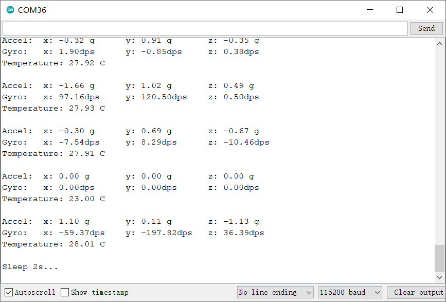
树莓派使用教程
准备
-
硬件
- 树莓派4代B型(或类似)主控板 x 1
- 六轴MEMS传感器 x 1
- 若干杜邦线 x 1
-
软件
接线图
-
将模块与树莓派按照连线图相连。I2C地址默认为0x69

安装驱动
- 启动树莓派的I2C接口。如已开启,可跳过该步骤。
打开终端(Terminal),键入如下指令,并回车:
sudo raspi-config
然后用上下键选择“ 5 Interfacing Options ”, 按回车进入,选择 “ P5 I2C ”, 按回车确认“ YES ”即可。重启树莓派主控板。
- 安装Python依赖库与git,树莓派需要联网。如已安装,可跳过该步骤。
在终端中,依次键入如下指令,并回车:
sudo apt-get update
sudo apt-get install build-essential python-dev python-smbus git
- 下载LIS系列驱动库。在终端中,依次键入如下指令,并回车:
cd Desktop
git clone https://github.com/DFRobot/DFRobot_ICG20660L
样例代码
- 样例代码1-读取x,y,z轴加速度数据(demo_get_accel_data.py)
- 样例代码2-读取陀螺仪的x,y,z轴的数据(demo_get_gyro_data.py)
- 样例代码3-读取陀螺仪、加速度和板载温度数据(demo_get_sensor_data.py)
- 样例代码4-读取加速度,温度、陀螺仪的14字节原始数据(demo_get_sensor_raw_data.py)
- 样例代码5-中断功能(demo_motion_wakr.py)
- 样例代码6-睡眠唤醒功能(demo_sleep.py)
样例代码1-读取x,y,z轴加速度数据(demo_get_accel_data.py)
- 在终端中,键入如下指令并回车,运行样例代码:
cd DFRobot_ICG20660L/Python/raspberrypi/examples
python demo_get_accel_data.py
- 晃动传感器结果如图

样例代码2-读取陀螺仪的x,y,z轴的数据(demo_get_gyro_data.py)
- 在终端中,键入如下指令并回车,运行样例代码:
cd DFRobot_ICG20660L/Python/raspberrypi/examples
python demo_get_gyro_data.py
- 晃动传感器结果如图

样例代码3-读取陀螺仪、加速度和板载温度数据(demo_get_sensor_data.py)
- 在终端中,键入如下指令并回车,运行样例代码:
cd DFRobot_ICG20660L/Python/raspberrypi/examples
- 晃动传感器结果如图
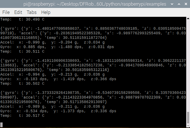
样例代码4-读取加速度,温度、陀螺仪的14字节原始数据(demo_get_sensor_raw_data.py)
- 在终端中,键入如下指令并回车,运行样例代码:
cd DFRobot_ICG20660L/Python/raspberrypi/examples
python demo_get_sensor_raw_data.py
- 晃动传感器结果如图

样例代码5-中断功能(demo_motion_wakr.py)
- 在终端中,键入如下指令并回车,运行样例代码:
cd DFRobot_ICG20660L/Python/raspberrypi/examples
python demo_motion_wakr.py
- 晃动传感器结果如图
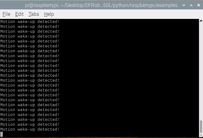
样例代码6-睡眠唤醒功能(demo_sleep.py)
- 在终端中,键入如下指令并回车,运行样例代码:
cd DFRobot_ICG20660L/Python/raspberrypi/examples
python demo_sleep.py
-
晃动传感器结果如图

常见问题
还没有客户对此产品有任何问题,欢迎通过qq或者论坛联系我们!
更多问题及有趣的应用,可以 访问论坛 进行查阅或发帖。
