产品简介
LIS2DW12三轴加速度计是一款超低功耗的线性加速度计,该传感器拥有两个独立的可编程中断及专用内部引擎,可实现超多功能,例如自由落体检测、纵向/横向检测、朝向检测、可配置的单击/双击识别、运动检测、运动唤醒以实现高级省电等。我们为您提供了以上功能的示例程序,方便您在项目中轻松使用。
该传感器具有±2g /±4g /±8g /±16g的用户可选全刻度,并能够以1.6 Hz至1600 Hz的输出数据速率测量加速度。它内置多种带宽的多种运行模式,您可以按需选择合适的模式。
注意:Gravity版本没有引出两个可编程中断引脚,若需要使用外部中断的高级功能,请购买Breakout版本
特性
- 可选量程:±2g /±4g /±8g /±16g
- 16位数据输出
- 简单易用的Gravity接口,无需焊接
- 拨扭开关可方便切换I2C地址
技术规格

- 工作电压:3.3V~5V
- 工作电流:8~10uA(低功耗低噪声模式)/0.12mA(高性能模式)
- 接口方式:Gravity-I2C接口
- I2C地址:0x19(默认地址)/0x18(可选)
- 可选标尺:±2g /±4g /±8g /±16g
- 频率:1.6Hz~1600Hz
- 16位数据输出
- 睡眠唤醒功能
- 超低噪声:1.3 mg RMS(低功耗模式)
- 32级FIFO(先进先出缓冲区)
- 万克高抗撞击能力
- ECOPACK®RoHS和“绿色”标准
- 工作温度:-40℃~+85℃
- 模块尺寸:27 x 27(mm)
- 安装孔尺寸:内径3.1mm/外径6mm
应用
- 自由落体检测
- 运动检测及记录
- 单击/双击检测
- 自平衡机器人
- 飞行器
- 人体动作识别
- 空气鼠标
- 游戏手柄
- 冲击检测及记录
引脚说明
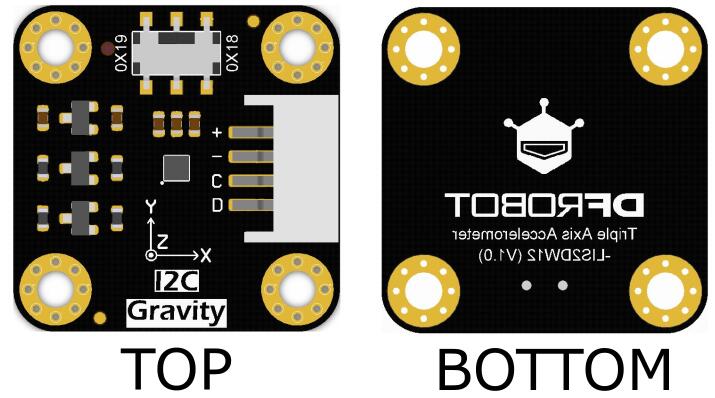
| 序号 | 丝印 | 功能描述 |
|---|---|---|
| 1 | VCC/+ | 5V / 3V3 |
| 2 | GND/- | GND |
| 3 | SCL/C | I2C时钟线 |
| 4 | SDA/D | I2C数据线 |
注意:拨钮开关可选择I2C地址为0x18或0x19。micro:bit(v1.5版本)的I2C地址与传感器I2C地址0x19冲突,所以请选择0x18。
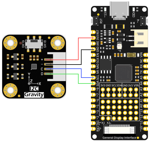
M0使用教程
请按接线图所示将传感器与M0(或其它主板)相连接即可。
准备
- 硬件
- 1 x Firebeetle Board-M0
- 1 x LIS2DW12三轴加速度计
- 若干 杜邦线
- 软件
- Arduino IDE, 点击下载Arduino IDE
- LIS系列库文件和示例程序
关于如何安装库文件,点击链接
-
样例代码
-
主要API接口函数列表
   DFRobot_LIS2DW12();

  /**
   * @brief Initialize the function
   * @return true(Initialization succeed)/fasle(Initialization failed)
   */
  bool begin(void);

  /**
   * @brief Get chip id
   * @return 8 bit serial number
   */
  uint8_t getID();

  /**
   * @brief Software reset to restore the value of all registers to the default value
   */
  void softReset();

  /**
   * @brief Enable the chip to continuously collect data
   * @param enable  true(continuous update)/false( output registers not updated until MSB and LSB read)
   */
  void continRefresh(bool enable);

  /**
   * @brief Set the filter processing mode
   * @param path path of filtering
                 eLPF   = 0x00,/< low-pass filter path selected>/
                 eHPF   = 0x10,/<high-pass filter path selected>/
   */
  void setFilterPath(ePath_t path);

  /**
   * @brief Set the  bandwidth of the data
   * @param bw bandwidth
                 eRateDiv_2  ,/<Rate/2 (up to Rate = 800 Hz, 400 Hz when Rate = 1600 Hz)>/
                 eRateDiv_4  ,/<Rate/4 (High Power/Low power)>*
                 eRateDiv_10 ,/<Rate/10 (HP/LP)>/
                 eRateDiv_20 ,/<Rate/20 (HP/LP)>/
   */
  void setFilterBandwidth(eBWFilter_t bw);

  /**
   * @brief Set power mode, there are two modes for the sensor to measure acceleration
   * @n       1.Continuous measurement In this mode, the sensor will continuously measure and store data in its register
   * @n       2.Single data conversion on demand mode In this mode, the sensor will not make a measurement unless it receives an external request
   * @param mode  power modes to choose from
                  eHighPerformance_14bit         /<High-Performance Mode,14-bit resolution>/
                  eContLowPwr4_14bit             /<Continuous measurement,Low-Power Mode 4(14-bit resolution)>/
                  eContLowPwr3_14bit             /<Continuous measurement,Low-Power Mode 3(14-bit resolution)>/
                  eContLowPwr2_14bit             /<Continuous measurement,Low-Power Mode 2(14-bit resolution)/
                  eContLowPwr1_12bit             /<Continuous measurement,Low-Power Mode 1(12-bit resolution)>/
                  eSingleLowPwr4_14bit           /<Single data conversion on demand mode,Low-Power Mode 4(14-bit resolution)>/
                  eSingleLowPwr3_14bit           /<Single data conversion on demand mode,Low-Power Mode 3(14-bit resolution)>/
                  eSingleLowPwr2_14bit           /<Single data conversion on demand mode,Low-Power Mode 2(14-bit resolution)>/
                  eSingleLowPwr1_12bit           /<Single data conversion on demand mode,Low-Power Mode 1(12-bit resolution)>/
                  eHighPerformanceLowNoise_14bit /<High-Performance Mode,Low-noise enabled,14-bit resolution>/
                  eContLowPwrLowNoise4_14bit     /<Continuous measurement,Low-Power Mode 4(14-bit resolution,Low-noise enabled)>/
                  eContLowPwrLowNoise3_14bit     /<Continuous measurement,Low-Power Mode 3(14-bit resolution,Low-noise enabled)>/
                  eContLowPwrLowNoise2_14bit     /<Continuous measurement,Low-Power Mode 2(14-bit resolution,Low-noise enabled)>/
                  eContLowPwrLowNoise1_12bit     /<Continuous measurement,Low-Power Mode 1(12-bit resolution,Low-noise enabled)>/
                  eSingleLowPwrLowNoise4_14bit   /<Single data conversion on demand mode,Low-Power Mode 4(14-bit resolution),Low-noise enabled>/
                  eSingleLowPwrLowNoise3_14bit   /<Single data conversion on demand mode,Low-Power Mode 3(14-bit resolution),Low-noise enabled>/
                  eSingleLowPwrLowNoise2_14bit   /<Single data conversion on demand mode,Low-Power Mode 2(14-bit resolution),Low-noise enabled>/
                  eSingleLowPwrLowNoise1_12bit   /<Single data conversion on demand mode,Low-Power Mode 1(12-bit resolution),Low-noise enabled>/
   */
  void setPowerMode(ePowerMode_t mode);

  /**
   * @brief Chip data collection rate setting
   * @param rate  Accelerometer frequency, 0-1600hz selection
                  eRate_0hz            /<Measurement off>/
                  eRate_1hz6           /<1.6hz, use only under low-power mode>/
                  eRate_12hz5          /<12.5hz>/
                  eRate_25hz
                  eRate_50hz
                  eRate_100hz
                  eRate_200hz
                  eRate_400hz         /<Use only under High-Performance mode>/
                  eRate_800hz         /<Use only under High-Performance mode>/
                  eRate_1k6hz         /<Use only under High-Performance mode>/
                  eSetSwTrig          /<The software triggers a single measurement>/
   */
  void setDataRate(eRate_t rate);

  /**
   * @brief Set the free fall time, or the number of free-fall samples. In a measurement, it will not be determined as a free fall event unless the samples are enough.
   * @param dur Freefall samples, range:0~31
   * @n time = dur * (1/rate)(unit:s)
     |                            An example of a linear relationship between an argument and time                            |
     |------------------------------------------------------------------------------------------------------------------------|
     |                |                     |                          |                          |                           |
     |  Data rate     |       25 Hz         |         100 Hz           |          400 Hz          |         = 800 Hz          |
     |------------------------------------------------------------------------------------------------------------------------|
     |   time         |dur*(1s/25)= dur*40ms|  dur*(1s/100)= dur*10ms  |  dur*(1s/400)= dur*2.5ms |  dur*(1s/800)= dur*1.25ms |
     |------------------------------------------------------------------------------------------------------------------------|
   */
  void setFreeFallDur(uint8_t dur);

  /**
   * @brief Select the interrupt event generated on the int1 pin
   * @param event  Interrupt event, when it occurs, a level jump will be generated on the int1 pin
                   eDoubleTap    = 0x08,/<Double tap event>/
                   eFreeFall     = 0x10,/<Free-fall event>/
                   eWakeUp       = 0x20,/<Wake-up event>/
                   eSingleTap    = 0x40,/<Single tap event>/
                   e6D           = 0x80,/<An event that changes the status of facing up/down/left/right/forward/back>/
   */
  void setInt1Event(eInt1Event_t event);

  /**
   * @brief Select the interrupt event generated on the int2 pin
   * @param event Interrupt event, when it occurs, a level jump will be generated on the int2 pin
                  eSleepChange = 0x40,/<Sleep change status routed to INT2 pad>/
                  eSleepState  = 0x80,/<Enable routing of SLEEP_STATE on INT2 pad>/
   */
  void setInt2Event(eInt2Event_t event);

  /**
   * @brief Set wake-up duration, when using the detection mode of eDetectAct in setActMode() function, it will collect data at a normal rate
   * @n     after the chip is awakened. Then after a period of time, the chip will continue to hibernate, collecting data at a frequency of 12.5hz.
   * @param dur duration,range: 0~3
     @n time = dur * (1/rate)(unit:s)
     |                           An example of a linear relationship between an argument and time                             |
     |------------------------------------------------------------------------------------------------------------------------|
     |                |                     |                          |                          |                           |
     |  Data rate     |       25 Hz         |         100 Hz           |          400 Hz          |         = 800 Hz          |
     |------------------------------------------------------------------------------------------------------------------------|
     |   time         |dur*(1s/25)= dur*40ms|  dur*(1s/100)= dur*10ms  |  dur*(1s/400)= dur*2.5ms |  dur*(1s/800)= dur*1.25ms |
     |------------------------------------------------------------------------------------------------------------------------|
   */
  void setWakeUpDur(uint8_t dur);

  /**
   * @brief Set the wake-up threshold, when the acceleration in a certain direction is greater than this value, a wake-up event will be triggered
   * @param th threshold ,unit:mg, the value is within the measurement range
   */
  void setWakeUpThreshold(float th);

  /**
   * @brief Set the mode of motion detection, the first mode will not detect whether the module is moving; the second, once set, will measure data at a lower
   * @n frequency to save consumption, and return to normal after detecting motion; the third can only detect whether the module is in sleep state.
   * @param mode Motion detection mode
                eNoDetection         /<No detection>/
                eDetectAct           /<Detect movement,the chip automatically goes to 12.5 Hz rate in the low-power mode>/
                eDetectStatMotion    /<Detect Motion, the chip detects acceleration below a fixed threshold but does not change either rate or operating mode>/
   */
  void setActMode(eActDetect_t mode);

  /**
   * @brief Set the range
   * @param range 量程
                   e2_g     = 2, /<±2g>/
                   e4_g     = 4, /<±4g>/
                   e8_g     = 8, /<±8g>/
                   e16_g    = 16, /< ±16g>/
   */
  void setRange(eRange_t range);

  /**
   * @brief Enable detect tap events in the Z direction
   * @param enable ture(Enable tap detection)\false(Disable tap detection)
   */
  void enableTapDetectionOnZ(bool enable);

  /**
   * @brief Enable detect tap events in the Y direction
   * @param enable ture(Enable tap detection)\false(Disable tap detection)
   */
  void enableTapDetectionOnY(bool enable);

  /**
   * @brief Enable detect tap events in the X direction
   * @param enable ture(Enable tap detection)\false(Disable tap detection)
   */
  void enableTapDetectionOnX(bool enable);

  /**
   * @brief Set the tap threshold in the X direction
   * @param th Threshold(mg),Can only be used in the range of 0~2g
   */
  void setTapThresholdOnX(float th);

  /**
   * @brief Set the tap threshold in the Y direction
   * @param th Threshold(mg),Can only be used in the range of 0~2g
   */
  void setTapThresholdOnY(float th);

  /**
   * @brief Set the tap threshold in the Z direction
   * @param th Threshold(mg),Can only be used in the range of 0~2g
   */
  void setTapThresholdOnZ(float th);

  /**
   * @brief Duration of maximum time gap for double-tap recognition. When double-tap
   * @n recognition is enabled, this register expresses the maximum time between two
   * @n successive detected taps to determine a double-tap event.
   * @param dur duration, range:0~15
   * @n time = dur * (1/rate)(unit:s)
     |                        An example of a linear relationship between an argument and time                                |
     |------------------------------------------------------------------------------------------------------------------------|
     |                |                     |                          |                          |                           |
     |  Data rate     |       25 Hz         |         100 Hz           |          400 Hz          |         = 800 Hz          |
     |------------------------------------------------------------------------------------------------------------------------|
     |   time         |dur*(1s/25)= dur*40ms|  dur*(1s/100)= dur*10ms  |  dur*(1s/400)= dur*2.5ms |  dur*(1s/800)= dur*1.25ms |
     |------------------------------------------------------------------------------------------------------------------------|
   */
  void setTapDur(uint8_t dur);

  /**
   * @brief Set the tap detection mode, detect single tap or both single tap and double tap
   * @param mode Tap detection mode
                     eOnlySingle   /<Detect single tap>/
                     eBothSingleDouble /<Detect both single tap and double tap>/
   */
  void setTapMode(eTapMode_t mode);

  /**
   * @brief Set Thresholds for 4D/6D, when the threshold of rotation exceeds the specified angle, a direction change event will occur.
   * @param degree   eDegrees80   /<80°>/
                     eDegrees70   /<70°>/
                     eDegrees60   /<60°>/
                     eDegrees50   /<50°>/
   */
  void set6DThreshold(e6DTh_t degree);

  /**
   * @brief Read the acceleration in the x direction
   * @return  Acceleration data from x(mg), the measurement range is ±2g, ±4g, ±8g or ±16g, set by the setRange() funciton.
   */
  int16_t readAccX();

  /**
   * @brief Read the acceleration in the y direction
   * @return  Acceleration data from y(mg), the measurement range is ±2g, ±4g, ±8g or ±16g, set by the setRange() funciton.
   */
  int16_t readAccY();

  /**
   * @brief Read the acceleration in the z direction
   * @return  Acceleration data from z(mg), the measurement range is ±2g, ±4g, ±8g or ±16g, set by the setRange() funciton.
   */
  int16_t readAccZ();

  /**
   * @brief Detect motion
   * @return true(Motion generated)/false(No motion)
   */
  bool actDetected();

  /**
   * @brief Detect free fall
   * @return true(Free-fall detected)/false(No free-fall)
   */
  bool freeFallDetected();

  /**
   * @brief Detect whether the direction of the chip changes when the chip is facing up/down/left/right/forward/back (ie 6D)
   * @return true(a change in position detected)/false(no event detected)
   */
  bool oriChangeDetected();

  /**
   * @brief Only in 6D (facing up/down/left/right/forward/backward) state can the function get the orientation of the sensor relative to the positive z-axis.
   * @return    eXDown  /<X is now down>/
                eXUp    /<X is now up>/
                eYDown  /<Y is now down>/
                eYUp    /<Y is now up>/
                eZDown  /<Z is now down>/
                eZUp    /<Z is now up>/
   */
  eOrient_t getOrientation();

  /**
   * @brief Tap detection, can detect it is double tap or single tap
   * @return   eSTap       /<Single Tap>/
               eDTap       /<double Tap>/
               eNoTap,     //No tap
                */
  eTap_t tapDetect();

  /**
   * @brief Tap direction source detection
   * @return   eDirXUp   /<Tap is detected in the positive direction of X>/
               eDirXDown /<Tap is detected in the negative direction of X>/
               eDirYUp   /<Tap is detected in the positive direction of Y>/
               eDirYDown /<Tap is detected in the negative direction of Y>/
               eDirZUp   /<Tap is detected in the positive direction of Z>/
               eDirZDown /<Tap is detected in the negative direction of Z>/
   */
  eTapDir_t getTapDirection();

  /**
   * @brief Wake-up motion direction detection
   * @return   eDirX    /<The chip is woken up by the motion in X direction>/
               eDirY    /<The chip is woken up by the motion in Y direction>/
               eDirZ    /<The chip is woken up by the motion in Z direction>/
               eDirError,/<Error detected>/
   */
  eWakeUpDir_t getWakeUpDir();

  /**
   * @brief In Single data conversion on demand mode, request a measurement.
   */
  void demandData();
样例代码1-读取x,y,z轴加速度(getAcceleration.ino)
- 选择getAcceleration.ino
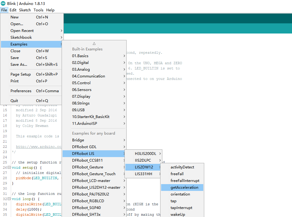
- 烧录程序
/**!
* @file getAcceleration.ino
* @brief Get the acceleration in the three directions of xyz, the range can be ±2g, ±4g, ±8g or ±16g, set by the setRange() function
* @n In this example, the continuous measurement mode is selected by default -- the acceleration data will be measured continuously according to the measuring rate.
* @n You can also use the single data conversion on demand mode 1. You need to select a suitable conversion mode in the setPowerMode() function
* @n 2. Fill in the setDataRate() function with the eSetSwTrig parameter
* @n 3. Request a measurement by the demandData() function
* @n When using SPI, chip select pin can be modified by changing the value of LIS2DW12_CS
* @copyright Copyright (c) 2010 DFRobot Co.Ltd (https://www.dfrobot.com)
* @licence The MIT License (MIT)
* @author [fengli](li.feng@dfrobot.com)
* @version V1.0
* @date 2021-01-16
* @get from https://www.dfrobot.com
* @https://github.com/DFRobot/DFRobot_LIS
*/
#include <DFRobot_LIS2DW12.h>
//When using I2C communication, use the following program to construct an object by DFRobot_LIS2DW12_I2C
/*!
* @brief Constructor
* @param pWire I2c controller
* @param addr I2C address(0x18/0x19)
*/
//DFRobot_LIS2DW12_I2C acce(&Wire,0x18);
DFRobot_LIS2DW12_I2C acce;
//When using SPI communication, use the following program to construct an object by DFRobot_LIS2DW12_SPI
#if defined(ESP32) || defined(ESP8266)
#define LIS2DW12_CS D3
#elif defined(__AVR__) || defined(ARDUINO_SAM_ZERO)
#define LIS2DW12_CS 3
#elif (defined NRF5)
#define LIS2DW12_CS 2 //The pin on the development board with the corresponding silkscreen printed as P2
#endif
/*!
* @brief Constructor
* @param cs Chip selection pinChip selection pin
* @param spi SPI controller
*/
//DFRobot_LIS2DW12_SPI acce(/*cs = */LIS2DW12_CS,&SPI);
//DFRobot_LIS2DW12_SPI acce(/*cs = */LIS2DW12_CS);
void setup(void){
Serial.begin(9600);
while(!acce.begin()){
Serial.println("Communication failed, check the connection and I2C address setting when using I2C communication.");
delay(1000);
}
Serial.print("chip id : ");
Serial.println(acce.getID(),HEX);
//Chip soft reset
acce.softReset();
//Set whether to collect data continuously
acce.continRefresh(true);
/**!
Set the sensor data collection rate:
eRate_0hz /<Measurement off>/
eRate_1hz6 /<1.6hz, use only under low-power mode>/
eRate_12hz5 /<12.5hz>/
eRate_25hz
eRate_50hz
eRate_100hz
eRate_200hz
eRate_400hz /<Use only under High-Performance mode>/
eRate_800hz /<Use only under High-Performance mode>/
eRate_1k6hz /<Use only under High-Performance mode>/
eSetSwTrig /<The software triggers a single measurement>/
*/
acce.setDataRate(DFRobot_LIS2DW12::eRate_50hz);
/**!
Set the sensor measurement range:
e2_g /<±2g>/
e4_g /<±4g>/
e8_g /<±8g>/
e16_g /< ±16g>/
*/
acce.setRange(DFRobot_LIS2DW12::e2_g);
/**!
Filter settings:
eLPF (Low pass filter)
eHPF (High pass filter)
*/
acce.setFilterPath(DFRobot_LIS2DW12::eLPF);
/**!
Set bandwidth:
eRateDiv_2 /<Rate/2 (up to Rate = 800 Hz, 400 Hz when Rate = 1600 Hz)>/
eRateDiv_4 /<Rate/4 (High Power/Low power)>*
eRateDiv_10 /<Rate/10 (HP/LP)>/
eRateDiv_20 /< Rate/20 (HP/LP)>/
*/
acce.setFilterBandwidth(DFRobot_LIS2DW12::eRateDiv_4);
/**!
Set power mode:
eHighPerformance_14bit /<High-Performance Mode,14-bit resolution>/
eContLowPwr4_14bit /<Continuous measurement,Low-Power Mode 4(14-bit resolution)>/
eContLowPwr3_14bit /<Continuous measurement,Low-Power Mode 3(14-bit resolution)>/
eContLowPwr2_14bit /<Continuous measurement,Low-Power Mode 2(14-bit resolution)/
eContLowPwr1_12bit /<Continuous measurement,Low-Power Mode 1(12-bit resolution)>/
eSingleLowPwr4_14bit /<Single data conversion on demand mode,Low-Power Mode 4(14-bit resolution)>/
eSingleLowPwr3_14bit /<Single data conversion on demand mode,Low-Power Mode 3(14-bit resolution)>/
eSingleLowPwr2_14bit /<Single data conversion on demand mode,Low-Power Mode 2(14-bit resolution)>/
eSingleLowPwr1_12bit /<Single data conversion on demand mode,Low-Power Mode 1(12-bit resolution)>/
eHighPerformanceLowNoise_14bit /<High-Performance Mode,Low-noise enabled,14-bit resolution>/
eContLowPwrLowNoise4_14bit /<Continuous measurement,Low-Power Mode 4(14-bit resolution,Low-noise enabled)>/
eContLowPwrLowNoise3_14bit /<Continuous measurement,Low-Power Mode 3(14-bit resolution,Low-noise enabled)>/
eContLowPwrLowNoise2_14bit /<Continuous measurement,Low-Power Mode 2(14-bit resolution,Low-noise enabled)>/
eContLowPwrLowNoise1_12bit /<Continuous measurement,Low-Power Mode 1(12-bit resolution,Low-noise enabled)>/
eSingleLowPwrLowNoise4_14bit /<Single data conversion on demand mode,Low-Power Mode 4(14-bit resolution),Low-noise enabled>/
eSingleLowPwrLowNoise3_14bit /<Single data conversion on demand mode,Low-Power Mode 3(14-bit resolution),Low-noise enabled>/
eSingleLowPwrLowNoise2_14bit /<Single data conversion on demand mode,Low-Power Mode 2(14-bit resolution),Low-noise enabled>/
eSingleLowPwrLowNoise1_12bit /<Single data conversion on demand mode,Low-Power Mode 1(12-bit resolution),Low-noise enabled>/
*/
acce.setPowerMode(DFRobot_LIS2DW12::eContLowPwrLowNoise2_14bit);
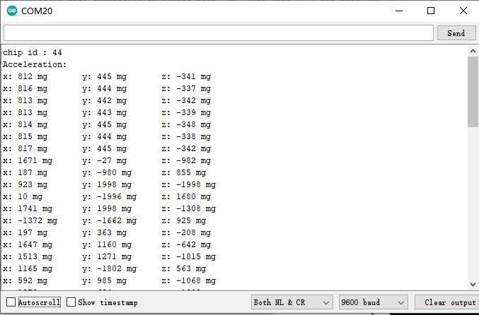
Serial.print("Acceleration:\n");
delay(100);
}
void loop(void){
//Request a measurement under single data conversion on demand mode
//acce.demandData();
//The mearsurement range is ±2g,±4g,±8g or ±16g, set by the setRange() function.
Serial.print("x: ");
//Read the acceleration in the x direction
Serial.print(acce.readAccX());
Serial.print(" mg \ty: ");
//Read the acceleration in the y direction
Serial.print(acce.readAccY());
Serial.print(" mg \tz: ");
//Read the acceleration in the z direction
Serial.print(acce.readAccZ());
Serial.println(" mg");
delay(300);
}
结果
样例代码2-睡眠唤醒功能(wakeUp.ino)
- 选择wakeUp.ino
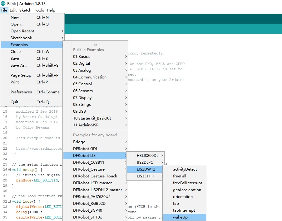
- 烧录程序
/**!
* @file wakeUp.ino
* @brief When the acceleration change in x, y or z direction is detected to exceed the threshold we set before, the chip will generate a wake-up event.
* @n By accessing the chip register, we can know which direction of movement wakes up the chip.
* @n In this example, it is necessary to set the wake-up duration by setWakeUpDur().
* @n When woken up, the chip will last for a while before it enters the sleep state.
* @n And to set the threshold by setWakeUpThreshold(). When the acceleration change exceeds this value, the eWakeUp event will be triggered.
* @n When using SPI, chip select pin can be modified by changing the value of LIS2DW12_CS
* @copyright Copyright (c) 2010 DFRobot Co.Ltd (https://www.dfrobot.com)
* @licence The MIT License (MIT)
* @author [fengli](li.feng@dfrobot.com)
* @version V1.0
* @date 2021-01-16
* @get from https://www.dfrobot.com
* @https://github.com/DFRobot/DFRobot_LIS
*/
#include <DFRobot_LIS2DW12.h>
//When using I2C communication, use the following program to construct an object by DFRobot_LIS2DW12_I2C
/*!
* @brief Constructor
* @param pWire I2c controller
* @param addr I2C address(0x18/0x19)
*/
//DFRobot_LIS2DW12_I2C acce(&Wire,0x18);
DFRobot_LIS2DW12_I2C acce;
//When using SPI communication, use the following program to construct an object by DFRobot_LIS2DW12_SPI
#if defined(ESP32) || defined(ESP8266)
#define LIS2DW12_CS D3
#elif defined(__AVR__) || defined(ARDUINO_SAM_ZERO)
#define LIS2DW12_CS 3
#elif (defined NRF5)
#define LIS2DW12_CS 2 //The pin on the development board with the corresponding silkscreen printed as P2
#endif
/*!
* @brief Constructor
* @param cs Chip selection pinChip selection pin
* @param spi SPI controller
*/
//DFRobot_LIS2DW12_SPI acce(/*cs = */LIS2DW12_CS,&SPI);
//DFRobot_LIS2DW12_SPI acce(/*cs = */LIS2DW12_CS);
void setup(void){
Serial.begin(9600);
while(!acce.begin()){
Serial.println("Communication failed, check the connection and I2C address setting when using I2C communication.");
delay(1000);
}
Serial.print("chip id : ");
Serial.println(acce.getID(),HEX);
//Chip soft reset
acce.softReset();
/**!
Set the sensor measurement range:
e2_g /<±2g>/
e4_g /<±4g>/
e8_g /<±8g>/
e16_g /< ±16g>/
*/
acce.setRange(DFRobot_LIS2DW12::e2_g);
/**!
Set power mode:
eHighPerformance_14bit /<High-Performance Mode,14-bit resolution>/
eContLowPwr4_14bit /<Continuous measurement,Low-Power Mode 4(14-bit resolution)>/
eContLowPwr3_14bit /<Continuous measurement,Low-Power Mode 3(14-bit resolution)>/
eContLowPwr2_14bit /<Continuous measurement,Low-Power Mode 2(14-bit resolution)/
eContLowPwr1_12bit /<Continuous measurement,Low-Power Mode 1(12-bit resolution)>/
eSingleLowPwr4_14bit /<Single data conversion on demand mode,Low-Power Mode 4(14-bit resolution)>/
eSingleLowPwr3_14bit /<Single data conversion on demand mode,Low-Power Mode 3(14-bit resolution)>/
eSingleLowPwr2_14bit /<Single data conversion on demand mode,Low-Power Mode 2(14-bit resolution)>/
eSingleLowPwr1_12bit /<Single data conversion on demand mode,Low-Power Mode 1(12-bit resolution)>/
eHighPerformanceLowNoise_14bit /<High-Performance Mode,Low-noise enabled,14-bit resolution>/
eContLowPwrLowNoise4_14bit /<Continuous measurement,Low-Power Mode 4(14-bit resolution,Low-noise enabled)>/
eContLowPwrLowNoise3_14bit /<Continuous measurement,Low-Power Mode 3(14-bit resolution,Low-noise enabled)>/
eContLowPwrLowNoise2_14bit /<Continuous measurement,Low-Power Mode 2(14-bit resolution,Low-noise enabled)>/
eContLowPwrLowNoise1_12bit /<Continuous measurement,Low-Power Mode 1(12-bit resolution,Low-noise enabled)>/
eSingleLowPwrLowNoise4_14bit /<Single data conversion on demand mode,Low-Power Mode 4(14-bit resolution),Low-noise enabled>/
eSingleLowPwrLowNoise3_14bit /<Single data conversion on demand mode,Low-Power Mode 3(14-bit resolution),Low-noise enabled>/
eSingleLowPwrLowNoise2_14bit /<Single data conversion on demand mode,Low-Power Mode 2(14-bit resolution),Low-noise enabled>/
eSingleLowPwrLowNoise1_12bit /<Single data conversion on demand mode,Low-Power Mode 1(12-bit resolution),Low-noise enabled>/
*/
acce.setPowerMode(DFRobot_LIS2DW12::eContLowPwrLowNoise1_12bit);
/**!
Set the sensor data collection rate:
eRate_0hz /<Measurement off>/
eRate_1hz6 /<1.6hz, use only under low-power mode>/
eRate_12hz5 /<12.5hz>/
eRate_25hz
eRate_50hz
eRate_100hz
eRate_200hz
eRate_400hz /<Use only under High-Performance mode>/
eRate_800hz /<Use only under High-Performance mode>/
eRate_1k6hz /<Use only under High-Performance mode>/
eSetSwTrig /<The software triggers a single measurement>/
*/
acce.setDataRate(DFRobot_LIS2DW12::eRate_200hz);
/**!
Filter settings:
eLPF(Low pass filter)
eHPF(High pass filter)
*/
acce.setFilterPath(DFRobot_LIS2DW12::eLPF);
/**
The wake-up duration – when woken up, the chip will last for a while before it enters the sleep state.
dur (0 ~ 3)
time = dur * (1/Rate)(unit:s)
| An example of a linear relationship between an argument and time |
|------------------------------------------------------------------------------------------------------------------------|
| | | | | |
| Data rate | 25 Hz | 100 Hz | 400 Hz | = 800 Hz |
|------------------------------------------------------------------------------------------------------------------------|
| time |dur*(1s/25)= dur*40ms| dur*(1s/100)= dur*10ms | dur*(1s/400)= dur*2.5ms | dur*(1s/800)= dur*1.25ms |
|------------------------------------------------------------------------------------------------------------------------|
*/
acce.setWakeUpDur(/*dur =*/2);
//Set wakeup threshold, when the acceleration change exceeds this value, the eWakeUp event will be triggered, unit:mg
//The value is within the range
acce.setWakeUpThreshold(/*threshold = */0.5);
/**!
Set the interrupt event of the int1 pin:
eDoubleTap(Double click)
eFreeFall(Free fall)
eWakeUp(wake)
eSingleTap(single-Click)
e6D(Orientation change check)
*/
acce.setInt1Event(DFRobot_LIS2DW12::eWakeUp);
/**!
Set the interrupt event of the int1 pin:
eSleepChange = 0x40,/<Sleep change status routed to INT2 pad>/
eSleepState = 0x80,/<Enable routing of SLEEP_STATE on INT2 pad>/
*/
//acce.setInt2Event(DFRobot_LIS2DW12::eSleepChange);
delay(100);
}
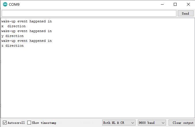
void loop(void){
//Wake-up event detected
if(acce.actDetected()){
Serial.print("wake-up event happened in ");
//Wake-up motion direction detection
DFRobot_LIS2DW12::eWakeUpDir_t dir = acce.getWakeUpDir();
if(dir == DFRobot_LIS2DW12::eDirX){
Serial.println("x direction");
}
if(dir == DFRobot_LIS2DW12::eDirY){
Serial.println("y direction");
}
if(dir == DFRobot_LIS2DW12::eDirZ){
Serial.println("z direction");
}
delay(100);
}
}
结果
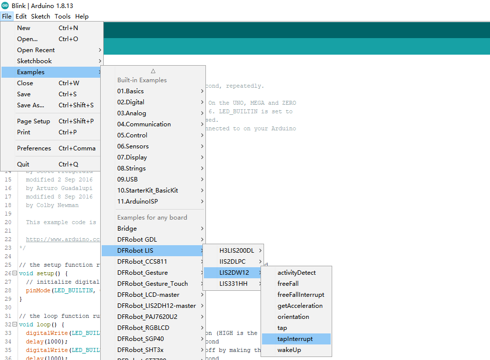
样例代码3-敲击检测功能(tap.ino)
- 选择tap.ino
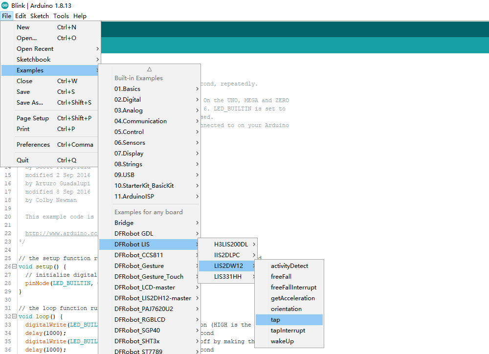
- 烧录程序
/**!
* @file tap.ino
* @brief Single tap and double tap detection, tapping the module or the desktop near the module both can trigger the tap event
* @n You can select to detect single tap or to detect both single tap and double tap by the setTapMode() function
* @n When using SPI, chip select pin can be modified by changing the value of LIS2DW12_CS
* @copyright Copyright (c) 2010 DFRobot Co.Ltd (https://www.dfrobot.com)
* @licence The MIT License (MIT)
* @author [fengli](li.feng@dfrobot.com)
* @version V1.0
* @date 2021-01-16
* @get from https://www.dfrobot.com
* @https://github.com/DFRobot/DFRobot_LIS
*/
#include <DFRobot_LIS2DW12.h>
//When using I2C communication, use the following program to construct an object by DFRobot_LIS2DW12_I2C
/*!
* @brief Constructor
* @param pWire I2c controller
* @param addr I2C address(0x18/0x19)
*/
//DFRobot_LIS2DW12_I2C acce(&Wire,0x18);
DFRobot_LIS2DW12_I2C acce;
//When using SPI communication, use the following program to construct an object by DFRobot_LIS2DW12_SPI
#if defined(ESP32) || defined(ESP8266)
#define LIS2DW12_CS D3
#elif defined(__AVR__) || defined(ARDUINO_SAM_ZERO)
#define LIS2DW12_CS 3
#elif (defined NRF5)
#define LIS2DW12_CS 2 //The pin on the development board with the corresponding silkscreen printed as P2
#endif
/*!
* @brief Constructor
* @param cs Chip selection pinChip selection pin
* @param spi SPI controller
*/
//DFRobot_LIS2DW12_SPI acce(/*cs = */LIS2DW12_CS,&SPI);
//DFRobot_LIS2DW12_SPI acce(/*cs = */LIS2DW12_CS);
void setup(void){
Serial.begin(9600);
while(!acce.begin()){
Serial.println("Communication failed, check the connection and I2C address setting when using I2C communication.");
delay(1000);
}
Serial.print("chip id : ");
Serial.println(acce.getID(),HEX);
//Chip soft reset
acce.softReset();
/**!
Set the sensor measurement range:
e2_g /<±2g>/
e4_g /<±4g>/
e8_g /<±8g>/
e16_g /< ±16g>/
*/
acce.setRange(DFRobot_LIS2DW12::e2_g);
/**!
Set power mode:
eHighPerformance_14bit /<High-Performance Mode,14-bit resolution>/
eContLowPwr4_14bit /<Continuous measurement,Low-Power Mode 4(14-bit resolution)>/
eContLowPwr3_14bit /<Continuous measurement,Low-Power Mode 3(14-bit resolution)>/
eContLowPwr2_14bit /<Continuous measurement,Low-Power Mode 2(14-bit resolution)/
eContLowPwr1_12bit /<Continuous measurement,Low-Power Mode 1(12-bit resolution)>/
eSingleLowPwr4_14bit /<Single data conversion on demand mode,Low-Power Mode 4(14-bit resolution)>/
eSingleLowPwr3_14bit /<Single data conversion on demand mode,Low-Power Mode 3(14-bit resolution)>/
eSingleLowPwr2_14bit /<Single data conversion on demand mode,Low-Power Mode 2(14-bit resolution)>/
eSingleLowPwr1_12bit /<Single data conversion on demand mode,Low-Power Mode 1(12-bit resolution)>/
eHighPerformanceLowNoise_14bit /<High-Performance Mode,Low-noise enabled,14-bit resolution>/
eContLowPwrLowNoise4_14bit /<Continuous measurement,Low-Power Mode 4(14-bit resolution,Low-noise enabled)>/
eContLowPwrLowNoise3_14bit /<Continuous measurement,Low-Power Mode 3(14-bit resolution,Low-noise enabled)>/
eContLowPwrLowNoise2_14bit /<Continuous measurement,Low-Power Mode 2(14-bit resolution,Low-noise enabled)>/
eContLowPwrLowNoise1_12bit /<Continuous measurement,Low-Power Mode 1(12-bit resolution,Low-noise enabled)>/
eSingleLowPwrLowNoise4_14bit /<Single data conversion on demand mode,Low-Power Mode 4(14-bit resolution),Low-noise enabled>/
eSingleLowPwrLowNoise3_14bit /<Single data conversion on demand mode,Low-Power Mode 3(14-bit resolution),Low-noise enabled>/
eSingleLowPwrLowNoise2_14bit /<Single data conversion on demand mode,Low-Power Mode 2(14-bit resolution),Low-noise enabled>/
eSingleLowPwrLowNoise1_12bit /<Single data conversion on demand mode,Low-Power Mode 1(12-bit resolution),Low-noise enabled>/
*/
acce.setPowerMode(DFRobot_LIS2DW12::eContLowPwrLowNoise1_12bit);
/**!
Set the sensor data collection rate:
eRate_0hz /<Measurement off>/
eRate_1hz6 /<1.6hz, use only under low-power mode>/
eRate_12hz5 /<12.5hz>/
eRate_25hz
eRate_50hz
eRate_100hz
eRate_200hz
eRate_400hz /<Use only under High-Performance mode>/
eRate_800hz /<Use only under High-Performance mode>/
eRate_1k6hz /<Use only under High-Performance mode>/
eSetSwTrig /<The software triggers a single measurement>/
*/
acce.setDataRate(DFRobot_LIS2DW12::eRate_800hz);
//Enable tap detection in the Z direction
acce.enableTapDetectionOnZ(true);
//Enable tap detection in Y direction
acce.enableTapDetectionOnY(true);
//Enable tap detection in the X direction
acce.enableTapDetectionOnX(true);
//The threshold setting in the X direction
//Threshold(mg),Can only be used in the range of ±2g
acce.setTapThresholdOnX(/*Threshold = */0.5);
//The threshold setting in the Y direction //Threshold(mg),Can only be used in the range of ±2g
acce.setTapThresholdOnY(/*Threshold = */0.5);
//The threshold setting in the Z direction //Threshold(mg),Can only be used in the range of ±2g)
acce.setTapThresholdOnZ(/*Threshold = */0.5);
/*
Set the interval time between two taps when detecting double tap
dur duration(0 ~ 15)
time = dur * (1/ODR)(unit:s)
| An example of a linear relationship between an argument and time |
|------------------------------------------------------------------------------------------------------------------------|
| | | | | |
| Data rate | 25 Hz | 100 Hz | 400 Hz | = 800 Hz |
|------------------------------------------------------------------------------------------------------------------------|
| time |dur*(1s/25)= dur*40ms| dur*(1s/100)= dur*10ms | dur*(1s/400)= dur*2.5ms | dur*(1s/800)= dur*1.25ms |
|------------------------------------------------------------------------------------------------------------------------|
*/
acce.setTapDur(/*dur=*/6);
/**!
Set tap detection mode:
eOnlySingle(Single tap)
eBothSingleDouble(Single tap and double tap)
*/
acce.setTapMode(DFRobot_LIS2DW12::eBothSingleDouble);
/**!
Set the interrupt source of the int1 pin:
eDoubleTap(Double tap)
eFreeFall(Free fall)
eWakeUp(wake)
eSingleTap(single-tap)
e6D(Orientation change check)
*/
acce.setInt1Event(DFRobot_LIS2DW12::eDoubleTap);
delay(1000);
}
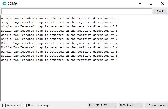
void loop(void){
//tap detected
DFRobot_LIS2DW12:: eTap_t tapEvent = acce.tapDetect();
//Tap source detection
DFRobot_LIS2DW12::eTapDir_t dir = acce.getTapDirection();
uint8_t tap = 0;
if(tapEvent == DFRobot_LIS2DW12::eSTap){
Serial.print("Single Tap Detected :");
tap = 1;
}
if(tapEvent == DFRobot_LIS2DW12::eDTap){
Serial.print("Double Tap Detected :");
tap = 1;
}
if(tap == 1){
if(dir == DFRobot_LIS2DW12::eDirXUp){
Serial.println("tap is detected in the positive direction of X");
}else if(dir == DFRobot_LIS2DW12::eDirXDown){
Serial.println("tap is detected in the negative direction of X");
}else if(dir == DFRobot_LIS2DW12::eDirYUp){
Serial.println("tap is detected in the positive direction of Y");
}else if(dir == DFRobot_LIS2DW12::eDirYDown){
Serial.println("tap is detected in the negative direction of Y");
}else if(dir == DFRobot_LIS2DW12::eDirZUp){
Serial.println("tap is detected in the positive direction of Z");
}else if(dir == DFRobot_LIS2DW12::eDirZDown){
Serial.println("tap is detected in the negative direction of Z");
}
delay(500);
tap = 0;
}
}
结果
样例代码4-敲击中断功能(tapInterrupt.ino) (仅Breakout版本可使用)
- 选择tapInterrupt.ino
- 烧录程序
/**!
 * @file tapInterrupt.ino
 * @brief tap interrupt detection, tapping the module and the desktop near the module can both trigger the interrupt level on pin int1.
 * @n When using SPI, chip select pin can be modified by changing the value of macro LIS2DW12_CS
 * @n In this example, the int2/int1 pin on the module needs to be connected to the interrupt pin on the motherboard. Default UNO(2),
 * @n                   Mega2560(2), Leonardo(3), microbit(P0),FireBeetle-ESP8266(D6),FireBeetle-ESP32((D6),FireBeetle-M0(6)
 * @copyright  Copyright (c) 2010 DFRobot Co.Ltd (https://www.dfrobot.com)
 * @licence     The MIT License (MIT)
 * @author [fengli](li.feng@dfrobot.com)
 * @version  V1.0
 * @date  2021-01-16
 * @get from https://www.dfrobot.com
 * @https://github.com/DFRobot/DFRobot_LIS
 */


#include <DFRobot_LIS2DW12.h>

//When using I2C communication, use the following program to construct an object by DFRobot_LIS2DW12_I2C
/*!
 * @brief Constructor
 * @param pWire I2c controller
 * @param addr  I2C address(0x18/0x19)
 */
//DFRobot_LIS2DW12_I2C acce(&Wire,0x18);
DFRobot_LIS2DW12_I2C acce;


//When using SPI communication, use the following program to construct an object by DFRobot_LIS2DW12_SPI
#if defined(ESP32) || defined(ESP8266)
#define LIS2DW12_CS  D3
#elif defined(__AVR__) || defined(ARDUINO_SAM_ZERO)
#define LIS2DW12_CS 3
#elif (defined NRF5)
#define LIS2DW12_CS 2  //The pin on the development board with the corresponding silkscreen printed as P2
#endif
/*!
 * @brief Constructor
 * @param cs  Chip selection pinChip selection pin
 * @param spi SPI controller
 */
//DFRobot_LIS2DW12_SPI acce(/*cs = */LIS2DW12_CS,&SPI);
//DFRobot_LIS2DW12_SPI acce(/*cs = */LIS2DW12_CS);

volatile uint8_t intFlag = 0;
void interEvent(){
  intFlag = 1;
}

void setup(void){

  Serial.begin(9600);
  while(!acce.begin()){
     Serial.println("Communication failed, check the connection and I2C address setting when using I2C communication.");
     delay(1000);
  }
  Serial.print("chip id : ");
  Serial.println(acce.getID(),HEX);
  //Chip soft reset
  acce.softReset();
  #if defined(ESP32) || defined(ESP8266)
  //The D6 pin is used as the interrupt pin by default, and other non-conflicting pins can also be selected as the external interrupt pin
  attachInterrupt(digitalPinToInterrupt(D6)/*Query the interrupt number of the D6 pin*/,interEvent,CHANGE);
  #elif defined(ARDUINO_SAM_ZERO)
  //The 5 pin is used as the interrupt pin by default, and other non-conflicting pins can also be selected as the external interrupt pin
  attachInterrupt(digitalPinToInterrupt(5)/*Query the interrupt number of the 5 pin*/,interEvent,CHANGE);
  #else
  /*    The Correspondence Table of AVR Series Arduino Interrupt Pins And Terminal Numbers
   * ---------------------------------------------------------------------------------------
   * |                                        |  DigitalPin  | 2  | 3  |                   |
   * |    Uno, Nano, Mini, other 328-based    |--------------------------------------------|
   * |                                        | Interrupt No | 0  | 1  |                   |
   * |-------------------------------------------------------------------------------------|
   * |                                        |    Pin       | 2  | 3  | 21 | 20 | 19 | 18 |
   * |               Mega2560                 |--------------------------------------------|
   * |                                        | Interrupt No | 0  | 1  | 2  | 3  | 4  | 5  |
   * |-------------------------------------------------------------------------------------|
   * |                                        |    Pin       | 3  | 2  | 0  | 1  | 7  |    |
   * |    Leonardo, other 32u4-based          |--------------------------------------------|
   * |                                        | Interrupt No | 0  | 1  | 2  | 3  | 4  |    |
   * |--------------------------------------------------------------------------------------
   */
  /*                      The Correspondence Table of micro:bit Interrupt Pins And Terminal Numbers
   * ---------------------------------------------------------------------------------------------------------------------------------------------
   * |             micro:bit                       | DigitalPin |P0-P20 can be used as an external interrupt                                     |
   * |  (When using as an external interrupt,      |---------------------------------------------------------------------------------------------|
   * |no need to set it to input mode with pinMode)|Interrupt No|Interrupt number is a pin digital value, such as P0 interrupt number 0, P1 is 1 |
   * |-------------------------------------------------------------------------------------------------------------------------------------------|
   */
  attachInterrupt(/*Interrupt No*/0,interEvent,CHANGE);//Open the external interrupt 0, connect INT1/2 to the digital pin of the main control:
     //UNO(2), Mega2560(2), Leonardo(3), microbit(P0).
  #endif

  /**!
    Set the sensor measurement range:
                   e2_g   /<±2g>/
                   e4_g   /<±4g>/
                   e8_g   /<±8g>/
                   e16_g  /< ±16g>/
  */
  acce.setRange(DFRobot_LIS2DW12::e2_g);

  /**!
   Set power mode:
       eHighPerformance_14bit         /<High-Performance Mode,14-bit resolution>/
       eContLowPwr4_14bit             /<Continuous measurement,Low-Power Mode 4(14-bit resolution)>/
       eContLowPwr3_14bit             /<Continuous measurement,Low-Power Mode 3(14-bit resolution)>/
       eContLowPwr2_14bit             /<Continuous measurement,Low-Power Mode 2(14-bit resolution)/
       eContLowPwr1_12bit             /<Continuous measurement,Low-Power Mode 1(12-bit resolution)>/
       eSingleLowPwr4_14bit           /<Single data conversion on demand mode,Low-Power Mode 4(14-bit resolution)>/
       eSingleLowPwr3_14bit           /<Single data conversion on demand mode,Low-Power Mode 3(14-bit resolution)>/
       eSingleLowPwr2_14bit           /<Single data conversion on demand mode,Low-Power Mode 2(14-bit resolution)>/
       eSingleLowPwr1_12bit           /<Single data conversion on demand mode,Low-Power Mode 1(12-bit resolution)>/
       eHighPerformanceLowNoise_14bit /<High-Performance Mode,Low-noise enabled,14-bit resolution>/
       eContLowPwrLowNoise4_14bit     /<Continuous measurement,Low-Power Mode 4(14-bit resolution,Low-noise enabled)>/
       eContLowPwrLowNoise3_14bit     /<Continuous measurement,Low-Power Mode 3(14-bit resolution,Low-noise enabled)>/
       eContLowPwrLowNoise2_14bit     /<Continuous measurement,Low-Power Mode 2(14-bit resolution,Low-noise enabled)>/
       eContLowPwrLowNoise1_12bit     /<Continuous measurement,Low-Power Mode 1(12-bit resolution,Low-noise enabled)>/
       eSingleLowPwrLowNoise4_14bit   /<Single data conversion on demand mode,Low-Power Mode 4(14-bit resolution),Low-noise enabled>/
       eSingleLowPwrLowNoise3_14bit   /<Single data conversion on demand mode,Low-Power Mode 3(14-bit resolution),Low-noise enabled>/
       eSingleLowPwrLowNoise2_14bit   /<Single data conversion on demand mode,Low-Power Mode 2(14-bit resolution),Low-noise enabled>/
       eSingleLowPwrLowNoise1_12bit   /<Single data conversion on demand mode,Low-Power Mode 1(12-bit resolution),Low-noise enabled>/
  */
  acce.setPowerMode(DFRobot_LIS2DW12::eContLowPwrLowNoise1_12bit);

  /**!
    Set the sensor data collection rate:
               eRate_0hz           /<Measurement off>/
               eRate_1hz6          /<1.6hz, Measurement off>/
               eRate_12hz5         /<12.5hz>/
               eRate_25hz
               eRate_50hz
               eRate_100hz
               eRate_200hz
               eRate_400hz       /<Use only under High-Performance mode>/
               eRate_800hz       /<Use only under High-Performance mode>/
               eRate_1k6hz       /<Use only under High-Performance mode>/
               eSetSwTrig        /<The software triggers a single measurement>/
  */
  acce.setDataRate(DFRobot_LIS2DW12::eRate_800hz);

  //Enable tap detection in the Z direction
  acce.enableTapDetectionOnZ(true);
  //Enable tap detection in Y direction
  acce.enableTapDetectionOnY(true);
  //Enable tap detection in the X direction
  acce.enableTapDetectionOnX(true);
  //The threshold setting in the X direction
  //Threshold(mg),Can only be used in the range of ±2g
  acce.setTapThresholdOnX(/*Threshold = */0.5);
  //The threshold setting in the Y direction   //Threshold(mg),Can only be used in the range of ±2g
  acce.setTapThresholdOnY(/*Threshold = */0.5);
  //The threshold setting in the Z direction   //Threshold(mg),Can only be used in the range of ±2g)
  acce.setTapThresholdOnZ(/*Threshold = */0.5);

  /*
    Set the interval time between two taps when detecting double tap
    dur duration(0 ~ 15)
    time = dur * (1/ODR)(unit:s)
    |                      An example of a linear relationship between an argument and time                                  |
    |------------------------------------------------------------------------------------------------------------------------|
    |                |                     |                          |                          |                           |
    |  Data rate     |       25 Hz         |         100 Hz           |          400 Hz          |         = 800 Hz          |
    |------------------------------------------------------------------------------------------------------------------------|
    |   time         |dur*(1s/25)= dur*40ms|  dur*(1s/100)= dur*10ms  |  dur*(1s/400)= dur*2.5ms |  dur*(1s/800)= dur*1.25ms |
    |------------------------------------------------------------------------------------------------------------------------|
  */
  acce.setTapDur(/*dur=*/6);

  /**!
    Set tap detection mode:
      eOnlySingle(single tap)
      eBothSingleDouble(Single tap and double tap)
  */
  acce.setTapMode(DFRobot_LIS2DW12::eBothSingleDouble);

  /**!
    Set the interrupt source of the int1 pin:
      eDoubleTap(Double tap)
      eFreeFall(Free fall)
      eWakeUp(wake)
      eSingleTap(single-tap)
      e6D(Orientation change check)
  */
  acce.setInt1Event(DFRobot_LIS2DW12::eDoubleTap);
  delay(1000);
}

void loop(void){
  if(intFlag == 1){
   //Tap detected
     DFRobot_LIS2DW12:: eTap_t tapEvent = acce.tapDetect();
    //Tap direction source detection
     DFRobot_LIS2DW12::eTapDir_t dir = acce.getTapDirection();
     if(tapEvent  == DFRobot_LIS2DW12::eSTap){
         Serial.print("Single Tap Detected :");
     }
     if(tapEvent  == DFRobot_LIS2DW12::eDTap){
         Serial.print("Double Tap Detected :");
     }
     if(dir == DFRobot_LIS2DW12::eDirXUp){
       Serial.println("tap is detected in the positive direction of X");
     }else if(dir == DFRobot_LIS2DW12::eDirXDown){
       Serial.println("tap is detected in the negative direction of X");
     }else if(dir == DFRobot_LIS2DW12::eDirYUp){
       Serial.println("tap is detected in the positive direction of Y");
     }else if(dir == DFRobot_LIS2DW12::eDirYDown){
       Serial.println("tap is detected in the negative direction of Y");
     }else if(dir == DFRobot_LIS2DW12::eDirZUp){
       Serial.println("tap is detected in the positive direction of Z");
     }else if(dir == DFRobot_LIS2DW12::eDirZDown){
       Serial.println("tap is detected in the negative direction of Z");
     }
     delay(500);
     intFlag = 0;

  }
}
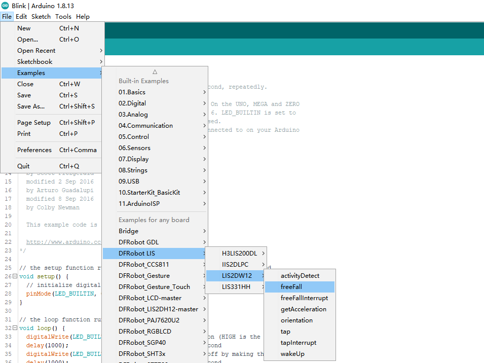
样例代码5-自由落体检测功能(freeFall.ino)
- 选择freeFall.ino
- 烧录程序
/**!
 * @file freeFall.ino
 * @brief Sensor module free fall detection, set the free fall time with the setFrDur() function to adjust the sensitivity of the detection.
 * @n The shorter the free fall time we set, the easier for the module to detect the free fall event
 * @n When using SPI, chip select pin can be modified by changing the value of LIS2DW12_CS
 * @copyright  Copyright (c) 2010 DFRobot Co.Ltd (https://www.dfrobot.com)
 * @licence     The MIT License (MIT)
 * @author [fengli](li.feng@dfrobot.com)
 * @version  V1.0
 * @date  2021-01-16
 * @get from https://www.dfrobot.com
 * @https://github.com/DFRobot/DFRobot_LIS
 */

#include <DFRobot_LIS2DW12.h>

//When using I2C communication, use the following program to construct an object by DFRobot_LIS2DW12_I2C
/*!
 * @brief Constructor
 * @param pWire I2c controller
 * @param addr  I2C address(0x18/0x19)
 */
//DFRobot_LIS2DW12_I2C acce(&Wire,0x18);
DFRobot_LIS2DW12_I2C acce;

//When using SPI communication, use the following program to construct an object by DFRobot_LIS2DW12_SPI
#if defined(ESP32) || defined(ESP8266)
#define LIS2DW12_CS  D3
#elif defined(__AVR__) || defined(ARDUINO_SAM_ZERO)
#define LIS2DW12_CS 3
#elif (defined NRF5)
#define LIS2DW12_CS 2  //The pin on the development board with the corresponding silkscreen printed as P2
#endif
/*!
 * @brief Constructor
 * @param cs  Chip selection pinChip selection pin
 * @param spi SPI controller
 */
//DFRobot_LIS2DW12_SPI acce(/*cs = */LIS2DW12_CS);
//DFRobot_LIS2DW12_SPI acce(/*cs = */LIS2DW12_CS,&SPI);

void setup(void){
  Serial.begin(9600);
  while(!acce.begin()){
     Serial.println("Communication failed, check the connection and I2C address setting when using I2C communication.");
     delay(1000);
  }
  Serial.print("chip id : ");
  Serial.println(acce.getID(),HEX);
  //Chip soft reset
  acce.softReset();
  //Set whether to collect data continuously
  acce.continRefresh(true);

  /**!
   Set power mode:
       eHighPerformance_14bit         /<High-Performance Mode,14-bit resolution>/
       eContLowPwr4_14bit             /<Continuous measurement,Low-Power Mode 4(14-bit resolution)>/
       eContLowPwr3_14bit             /<Continuous measurement,Low-Power Mode 3(14-bit resolution)>/
       eContLowPwr2_14bit             /<Continuous measurement,Low-Power Mode 2(14-bit resolution)/
       eContLowPwr1_12bit             /<Continuous measurement,Low-Power Mode 1(12-bit resolution)>/
       eSingleLowPwr4_14bit           /<Single data conversion on demand mode,Low-Power Mode 4(14-bit resolution)>/
       eSingleLowPwr3_14bit           /<Single data conversion on demand mode,Low-Power Mode 3(14-bit resolution)>/
       eSingleLowPwr2_14bit           /<Single data conversion on demand mode,Low-Power Mode 2(14-bit resolution)>/
       eSingleLowPwr1_12bit           /<Single data conversion on demand mode,Low-Power Mode 1(12-bit resolution)>/
       eHighPerformanceLowNoise_14bit /<High-Performance Mode,Low-noise enabled,14-bit resolution>/
       eContLowPwrLowNoise4_14bit     /<Continuous measurement,Low-Power Mode 4(14-bit resolution,Low-noise enabled)>/
       eContLowPwrLowNoise3_14bit     /<Continuous measurement,Low-Power Mode 3(14-bit resolution,Low-noise enabled)>/
       eContLowPwrLowNoise2_14bit     /<Continuous measurement,Low-Power Mode 2(14-bit resolution,Low-noise enabled)>/
       eContLowPwrLowNoise1_12bit     /<Continuous measurement,Low-Power Mode 1(12-bit resolution,Low-noise enabled)>/
       eSingleLowPwrLowNoise4_14bit   /<Single data conversion on demand mode,Low-Power Mode 4(14-bit resolution),Low-noise enabled>/
       eSingleLowPwrLowNoise3_14bit   /<Single data conversion on demand mode,Low-Power Mode 3(14-bit resolution),Low-noise enabled>/
       eSingleLowPwrLowNoise2_14bit   /<Single data conversion on demand mode,Low-Power Mode 2(14-bit resolution),Low-noise enabled>/
       eSingleLowPwrLowNoise1_12bit   /<Single data conversion on demand mode,Low-Power Mode 1(12-bit resolution),Low-noise enabled>/
  */
  acce.setPowerMode(DFRobot_LIS2DW12::eContLowPwr4_14bit);

  /**!
    Set the sensor data collection rate:
               eRate_0hz           /<Measurement off>/
               eRate_1hz6          /<1.6hz, use only under low-power mode>/
               eRate_12hz5         /<12.5hz>/
               eRate_25hz
               eRate_50hz
               eRate_100hz
               eRate_200hz
               eRate_400hz       /<Use only under High-Performance mode>/
               eRate_800hz       /<Use only under High-Performance mode>/
               eRate_1k6hz       /<Use only under High-Performance mode>/
               eSetSwTrig        /<The software triggers a single measurement>/
  */
  acce.setDataRate(DFRobot_LIS2DW12::eRate_100hz);

  /**!
    Set the sensor measurement range:
                   e2_g   /<±2g>/
                   e4_g   /<±4g>/
                   e8_g   /<±8g>/
                   e16_g  /< ±16g>/
  */
  acce.setRange(DFRobot_LIS2DW12::e2_g);

  /**
   * Set the free fall time (Or the number of free-fall samples. In a measurement, it will not be determined as a free-fall event unless the free-fall samples are sufficient.)
    dur (0 ~ 31)
    time = dur * (1/Rate)(unit:s)
    |                     An example of a linear relationship between an argument and time                                   |
    |------------------------------------------------------------------------------------------------------------------------|
    |                |                     |                          |                          |                           |
    |  Data rate     |       25 Hz         |         100 Hz           |          400 Hz          |         = 800 Hz          |
    |------------------------------------------------------------------------------------------------------------------------|
    |   time         |dur*(1s/25)= dur*40ms|  dur*(1s/100)= dur*10ms  |  dur*(1s/400)= dur*2.5ms |  dur*(1s/800)= dur*1.25ms |
    |------------------------------------------------------------------------------------------------------------------------|
  */
  acce.setFreeFallDur(/*dur = */3);

  /**!
    Set the interrupt source of the int1 pin:
    eDoubleTap(Double click)
    eFreeFall(Free fall)
    eWakeUp(wake)
    eSingleTap(single-Click)
    e6D(Orientation change check)
  */
  acce.setInt1Event(DFRobot_LIS2DW12::eFreeFall);
  delay(100);
}

void loop(void){
   //Free fall event detected
   if(acce.freeFallDetected()){
      Serial.println("free fall detected");
      delay(300);
   }
}
结果

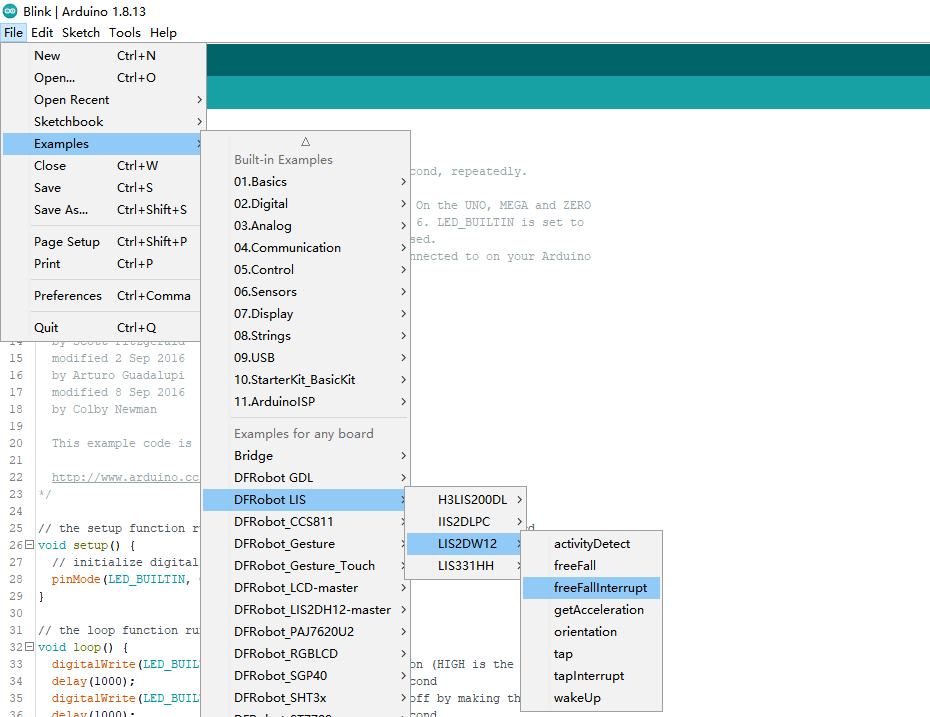
样例代码6-自由落体中断功能(freeFallInterrupt.ino)(仅Breakout版本可使用)
- 选择freeFallInterrupt.ino
- 烧录程序
/**!
 * @file freeFallInterrupt.ino
 * @brief Interrupt detection of free fall, an interrupt signal will be generated in int1 once a free fall event occurs.
 * @n When a free-fall motion is detected, it will be printed on the serial port.
 * @n When using SPI, chip select pin can be modified by changing the value of LIS2DW12_CS
 * @n In this example, the int2/int1 pin on the module needs to be connected to the interrupt pin on the motherboard. Default UNO(2),
 * @n                                 Mega2560(2), Leonardo(3), microbit(P0),FireBeetle-ESP8266(D6),FireBeetle-ESP32((D6),FireBeetle-M0(6)
 * @copyright  Copyright (c) 2010 DFRobot Co.Ltd (https://www.dfrobot.com)
 * @licence     The MIT License (MIT)
 * @author [fengli](li.feng@dfrobot.com)
 * @version  V1.0
 * @date  2021-01-16
 * @get from https://www.dfrobot.com
 * @https://github.com/DFRobot/DFRobot_LIS
 */
#include <DFRobot_LIS2DW12.h>

//When using I2C communication, use the following program to construct an object by DFRobot_LIS2DW12_I2C
/*!
 * @brief Constructor
 * @param pWire I2c controller
 * @param addr  I2C address(0x18/0x19)
 */
//DFRobot_LIS2DW12_I2C acce(&Wire,0x18);
DFRobot_LIS2DW12_I2C acce;

//When using SPI communication, use the following program to construct an object by DFRobot_LIS2DW12_SPI
#if defined(ESP32) || defined(ESP8266)
#define LIS2DW12_CS  D3
#elif defined(__AVR__) || defined(ARDUINO_SAM_ZERO)
#define LIS2DW12_CS 3
#elif (defined NRF5)
#define LIS2DW12_CS P3
#endif
/*!
 * @brief Constructor
 * @param cs Chip selection pinChip selection pin
 * @param spi SPI controller
 */
//DFRobot_LIS2DW12_SPI acce(/*cs = */LIS2DW12_CS,&SPI);
//DFRobot_LIS2DW12_SPI acce(/*cs = */LIS2DW12_CS);

volatile uint8_t intFlag = 0;
void interEvent(){
  intFlag = 1;
}

void setup(void){

  Serial.begin(9600);
  while(!acce.begin()){
     Serial.println("Communication failed, check the connection and I2C address setting when using I2C communication.");
     delay(1000);
  }
  Serial.print("chip id : ");
  Serial.println(acce.getID(),HEX);

  #if defined(ESP32) || defined(ESP8266)
  //By default, the D6 pin is used as the interrupt pin, and other non-conflicting pins can also be selected as the external interrupt pin.
  attachInterrupt(digitalPinToInterrupt(D6)/*Query the interrupt number of the D6 pin*/,interEvent,CHANGE);
  #elif defined(ARDUINO_SAM_ZERO)
  //By default, the 5 pin is used as the interrupt pin, and other non-conflicting pins can also be selected as the external interrupt pin.
  attachInterrupt(digitalPinToInterrupt(5)/*Query the interrupt number of the pin 5*/,interEvent,CHANGE);
  #else
  /*    The Correspondence Table of AVR Series Arduino Interrupt Pins And Terminal Numbers
   * ---------------------------------------------------------------------------------------
   * |                                        |  DigitalPin  | 2  | 3  |                   |
   * |    Uno, Nano, Mini, other 328-based    |--------------------------------------------|
   * |                                        | Interrupt No | 0  | 1  |                   |
   * |-------------------------------------------------------------------------------------|
   * |                                        |    Pin       | 2  | 3  | 21 | 20 | 19 | 18 |
   * |               Mega2560                 |--------------------------------------------|
   * |                                        | Interrupt No | 0  | 1  | 2  | 3  | 4  | 5  |
   * |-------------------------------------------------------------------------------------|
   * |                                        |    Pin       | 3  | 2  | 0  | 1  | 7  |    |
   * |    Leonardo, other 32u4-based          |--------------------------------------------|
   * |                                        | Interrupt No | 0  | 1  | 2  | 3  | 4  |    |
   * |--------------------------------------------------------------------------------------
   */
  /*                      The Correspondence Table of micro:bit Interrupt Pins And Terminal Numbers
   * ---------------------------------------------------------------------------------------------------------------------------------------------
   * |             micro:bit                       | DigitalPin |P0-P20 can be used as an external interrupt                                     |
   * |  (When using as an external interrupt,      |---------------------------------------------------------------------------------------------|
   * |no need to set it to input mode with pinMode)|Interrupt No|Interrupt number is a pin digital value, such as P0 interrupt number 0, P1 is 1 |
   * |-------------------------------------------------------------------------------------------------------------------------------------------|
   */
  attachInterrupt(/*Interrupt No*/0,interEvent,CHANGE);//Enable the external interrupt 0, connect INT1/2 to the digital pin of the main control:
     //UNO(2), Mega2560(2), Leonardo(3), microbit(P0).
  #endif

  //Chip soft reset
  acce.softReset();
  //Set whether to collect data continuously
  acce.continRefresh(true);

  /**!
   Set power mode:
       eHighPerformance_14bit         /<High-Performance Mode,14-bit resolution>/
       eContLowPwr4_14bit             /<Continuous measurement,Low-Power Mode 4(14-bit resolution)>/
       eContLowPwr3_14bit             /<Continuous measurement,Low-Power Mode 3(14-bit resolution)>/
       eContLowPwr2_14bit             /<Continuous measurement,Low-Power Mode 2(14-bit resolution)/
       eContLowPwr1_12bit             /<Continuous measurement,Low-Power Mode 1(12-bit resolution)>/
       eSingleLowPwr4_14bit           /<Single data conversion on demand mode,Low-Power Mode 4(14-bit resolution)>/
       eSingleLowPwr3_14bit           /<Single data conversion on demand mode,Low-Power Mode 3(14-bit resolution)>/
       eSingleLowPwr2_14bit           /<Single data conversion on demand mode,Low-Power Mode 2(14-bit resolution)>/
       eSingleLowPwr1_12bit           /<Single data conversion on demand mode,Low-Power Mode 1(12-bit resolution)>/
       eHighPerformanceLowNoise_14bit /<High-Performance Mode,Low-noise enabled,14-bit resolution>/
       eContLowPwrLowNoise4_14bit     /<Continuous measurement,Low-Power Mode 4(14-bit resolution,Low-noise enabled)>/
       eContLowPwrLowNoise3_14bit     /<Continuous measurement,Low-Power Mode 3(14-bit resolution,Low-noise enabled)>/
       eContLowPwrLowNoise2_14bit     /<Continuous measurement,Low-Power Mode 2(14-bit resolution,Low-noise enabled)>/
       eContLowPwrLowNoise1_12bit     /<Continuous measurement,Low-Power Mode 1(12-bit resolution,Low-noise enabled)>/
       eSingleLowPwrLowNoise4_14bit   /<Single data conversion on demand mode,Low-Power Mode 4(14-bit resolution),Low-noise enabled>/
       eSingleLowPwrLowNoise3_14bit   /<Single data conversion on demand mode,Low-Power Mode 3(14-bit resolution),Low-noise enabled>/
       eSingleLowPwrLowNoise2_14bit   /<Single data conversion on demand mode,Low-Power Mode 2(14-bit resolution),Low-noise enabled>/
       eSingleLowPwrLowNoise1_12bit   /<Single data conversion on demand mode,Low-Power Mode 1(12-bit resolution),Low-noise enabled>/
  */
  acce.setPowerMode(DFRobot_LIS2DW12::eContLowPwr4_14bit);

  /**!
    Set the sensor data collection rate:
               eRate_0hz           /<Measurement off>/
               eRate_1hz6          /<1.6hz, use only under low-power mode>/
               eRate_12hz5         /<12.5hz>/
               eRate_25hz
               eRate_50hz
               eRate_100hz
               eRate_200hz
               eRate_400hz       /<Use only under High-Performance mode>/
               eRate_800hz       /<Use only under High-Performance mode>/
               eRate_1k6hz       /<Use only under High-Performance mode>/
               eSetSwTrig        /<The software triggers a single measurement.>/
  */
  acce.setDataRate(DFRobot_LIS2DW12::eRate_100hz);

  /**!
    Set the sensor measurement range:
                   e2_g   /<±2g>/
                   e4_g   /<±4g>/
                   e8_g   /<±8g>/
                   e16_g  /< ±16g>/
  */
  acce.setRange(DFRobot_LIS2DW12::e2_g);

  //The duration of free fall (0~31), the larger the value, the longer it takes to detect a free fall event
  /**
   * Set the free fall time (Or the number of free-fall samples. In a measurement, it will not be determined as a free fall event unless the samples are enough.)
    dur range(0 ~ 31)
    time = dur * (1/Rate)(unit:s)
    |                                 An example of a linear relationship between an argument and time                                                        |
    |------------------------------------------------------------------------------------------------------------------------|
    |                |                     |                          |                          |                           |
    |  Data rate     |       25 Hz         |         100 Hz           |          400 Hz          |         = 800 Hz          |
    |------------------------------------------------------------------------------------------------------------------------|
    |   time         |dur*(1s/25)= dur*40ms|  dur*(1s/100)= dur*10ms  |  dur*(1s/400)= dur*2.5ms |  dur*(1s/800)= dur*1.25ms |
    |------------------------------------------------------------------------------------------------------------------------|
   */
  acce.setFreeFallDur(/*dur = */3);

  /**!
    Set the interrupt source of the int1 pin:
    eDoubleTap(Double click)
    eFreeFall(Free fall)
    eWakeUp(wake)
    eSingleTap(single-Click)
    e6D(Orientation change check)
  */
  acce.setInt1Event(DFRobot_LIS2DW12::eFreeFall);
  delay(100);
}

void loop(void){

   if(intFlag == 1){
   //Free fall event detected
   delay(100);
   if(acce.freeFallDetected()){
      Serial.println("free fall detected");
      delay(200);
   }
    intFlag = 0;
   }
}
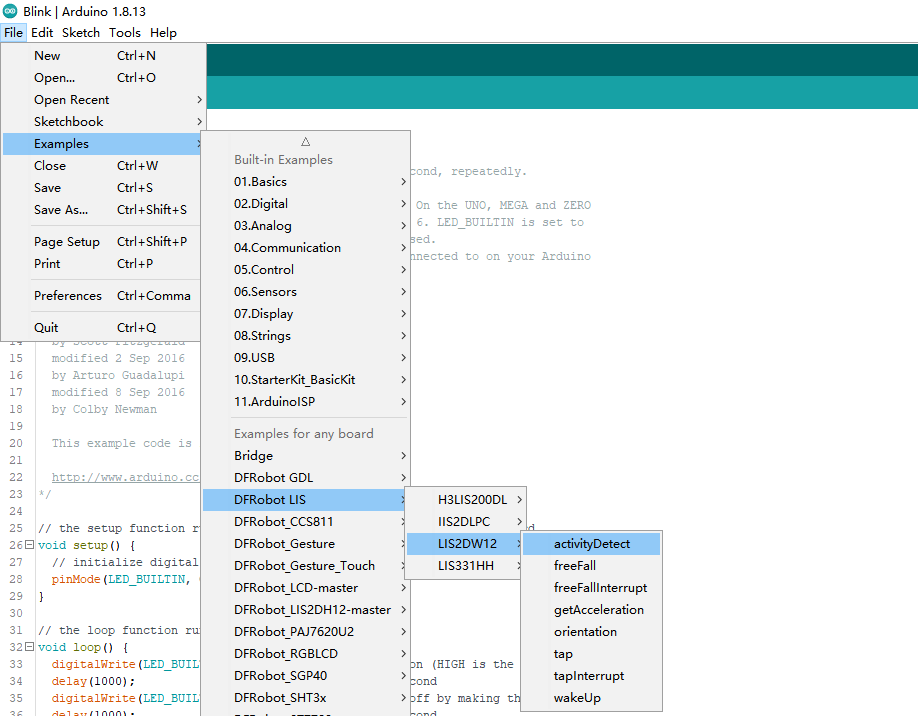
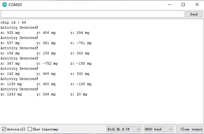
样例代码7-运动检测功能(activityDetect.ino)
- 选择activityDetect.ino
- 烧录程序
/**!
 * @file activityDetect.ino
 * @brief Motion detection, can detect whether the module is moving
 * @n It’s necessary to go into low power mode before using this function. Then call setActMode() to make the chip in sleep mode.
 * @n In this state, the measurement rate is 12.5hz.
 * @n When the acceleration change in a certain direction is detected to exceed the threshold, the measurement rate will be increased
 * @n to the normal rate we set before. The threshold can be set by the setWakeUpThreshold() function.
 * @n But if the move stops moving, also, the acceleration change in the three directions is less than the threshold, the chip will turn into sleep
 * @n mode after a period of time. This duration time can be set by the setWakeUpDur() function.
 * @n When using SPI, chip select pin can be modified by changing the value of LIS2DW12_CS.
 * @copyright  Copyright (c) 2010 DFRobot Co.Ltd (https://www.dfrobot.com)
 * @licence     The MIT License (MIT)
 * @author [fengli](li.feng@dfrobot.com)
 * @version  V1.0
 * @date  2021-01-16
 * @get from https://www.dfrobot.com
 * @https://github.com/DFRobot/DFRobot_LIS
 */

#include <DFRobot_LIS2DW12.h>

//When using I2C communication, use the following program to construct an object by DFRobot_LIS2DW12_I2C
/*!
 * @brief Constructor
 * @param pWire I2c controller
 * @param addr  I2C address(0x18/0x19)
 */
//DFRobot_LIS2DW12_I2C acce(&Wire,0x18);
DFRobot_LIS2DW12_I2C acce;

//When using SPI communication, use the following program to construct an object by DFRobot_LIS2DW12_SPI
#if defined(ESP32) || defined(ESP8266)
#define LIS2DW12_CS  D3
#elif defined(__AVR__) || defined(ARDUINO_SAM_ZERO)
#define LIS2DW12_CS 3
#elif (defined NRF5)
#define LIS2DW12_CS 2  //The pin on the development board with the corresponding silkscreen printed as P2
#endif
/*!
 * @brief Constructor
 * @param cs  Chip selection pinChip selection pin
 * @param spi SPI controller
 */
//DFRobot_LIS2DW12_SPI acce(/*cs = */LIS2DW12_CS);
//DFRobot_LIS2DW12_SPI acce(/*cs = */LIS2DW12_CS,&SPI);

void setup(void){
  Serial.begin(9600);
  while(!acce.begin()){
     Serial.println("Communication failed, check the connection and I2C address setting when using I2C communication.");
     delay(1000);
  }
  Serial.print("chip id : ");
  Serial.println(acce.getID(),HEX);
  //Software reset
  acce.softReset();

  /**!
    Set the sensor measurement range:
                   e2_g   /<±2g>/
                   e4_g   /<±4g>/
                   e8_g   /<±8g>/
                   e16_g  /<±16g>/
  */
  acce.setRange(DFRobot_LIS2DW12::e2_g);

  /**!
    Filter settings:
           eLPF(Low pass filter)
           eHPF(High pass filter)
  */
  acce.setFilterPath(DFRobot_LIS2DW12::eLPF);

  /**!
    Set bandwidth:
        eRateDiv_2  ,/<Rate/2 (up to Rate = 800 Hz, 400 Hz when Rate = 1600 Hz)>/
        eRateDiv_4  ,/<Rate/4 (High Power/Low power)>*
        eRateDiv_10 ,/<Rate/10 (HP/LP)>/
        eRateDiv_20 ,/< Rate/20 (HP/LP)>/
  */
  acce.setFilterBandwidth(DFRobot_LIS2DW12::eRateDiv_4);

  /**
     Wake-up duration: when using the detection mode of eDetectAct in the setActMode() function, it will collect data
   at a normal rate after the chip is awakened. Then after a period of time, the chip will continue to hibernate, collecting data at a frequency of 12.5hz.
    dur (0 ~ 3)
    time = dur * (1/Rate)(unit:s)
    |                    An example of a linear relationship between an argument and time                                    |
    |------------------------------------------------------------------------------------------------------------------------|
    |                |                     |                          |                          |                           |
    |  Data rate     |       25 Hz         |         100 Hz           |          400 Hz          |         = 800 Hz          |
    |------------------------------------------------------------------------------------------------------------------------|
    |   time         |dur*(1s/25)= dur*40ms|  dur*(1s/100)= dur*10ms  |  dur*(1s/400)= dur*2.5ms |  dur*(1s/800)= dur*1.25ms |
    |------------------------------------------------------------------------------------------------------------------------|
   */
  acce.setWakeUpDur(/*dur = */2);

  //Set wakeup threshold, when the acceleration change exceeds this value, the eWakeUp event will be triggered, unit:mg
  //The value is within the range.
  acce.setWakeUpThreshold(/*threshold = */0.2);

  /**!
   Set power mode:
       eHighPerformance_14bit         /<High-Performance Mode,14-bit resolution>/
       eContLowPwr4_14bit             /<Continuous measurement,Low-Power Mode 4(14-bit resolution)>/
       eContLowPwr3_14bit             /<Continuous measurement,Low-Power Mode 3(14-bit resolution)>/
       eContLowPwr2_14bit             /<Continuous measurement,Low-Power Mode 2(14-bit resolution)/
       eContLowPwr1_12bit             /<Continuous measurement,Low-Power Mode 1(12-bit resolution)>/
       eSingleLowPwr4_14bit           /<Single data conversion on demand mode,Low-Power Mode 4(14-bit resolution)>/
       eSingleLowPwr3_14bit           /<Single data conversion on demand mode,Low-Power Mode 3(14-bit resolution)>/
       eSingleLowPwr2_14bit           /<Single data conversion on demand mode,Low-Power Mode 2(14-bit resolution)>/
       eSingleLowPwr1_12bit           /<Single data conversion on demand mode,Low-Power Mode 1(12-bit resolution)>/
       eHighPerformanceLowNoise_14bit /<High-Performance Mode,Low-noise enabled,14-bit resolution>/
       eContLowPwrLowNoise4_14bit     /<Continuous measurement,Low-Power Mode 4(14-bit resolution,Low-noise enabled)>/
       eContLowPwrLowNoise3_14bit     /<Continuous measurement,Low-Power Mode 3(14-bit resolution,Low-noise enabled)>/
       eContLowPwrLowNoise2_14bit     /<Continuous measurement,Low-Power Mode 2(14-bit resolution,Low-noise enabled)>/
       eContLowPwrLowNoise1_12bit     /<Continuous measurement,Low-Power Mode 1(12-bit resolution,Low-noise enabled)>/
       eSingleLowPwrLowNoise4_14bit   /<Single data conversion on demand mode,Low-Power Mode 4(14-bit resolution),Low-noise enabled>/
       eSingleLowPwrLowNoise3_14bit   /<Single data conversion on demand mode,Low-Power Mode 3(14-bit resolution),Low-noise enabled>/
       eSingleLowPwrLowNoise2_14bit   /<Single data conversion on demand mode,Low-Power Mode 2(14-bit resolution),Low-noise enabled>/
       eSingleLowPwrLowNoise1_12bit   /<Single data conversion on demand mode,Low-Power Mode 1(12-bit resolution),Low-noise enabled>/
  */
  acce.setPowerMode(DFRobot_LIS2DW12::eContLowPwrLowNoise1_12bit);

  /**!
    Set the mode of motion detection:
    eNoDetection       /<No detection>/
    eDetectAct         /<If set this mode, the rate of the chip will drop to 12.5hz and turn into normal measurement frequency
                        after the eWakeUp event is generated.>/
    eDetectStatMotion  /<In this mode, it can only detect if the chip is in sleep mode without changing the measurement frequency
                         and power mode, continuously measuring the data at normal frequency.>/
  */
  acce.setActMode(DFRobot_LIS2DW12::eDetectAct);

  /**!
    Set the interrupt source of the int1 pin:
    eDoubleTap(Double click)
    eFreeFall(Free fall)
    eWakeUp(wake up)
    eSingleTap(single-Click)
    e6D(Orientation change check)
  */
  acce.setInt1Event(DFRobot_LIS2DW12::eWakeUp);

  /**!
    Set the sensor data collection rate:
               eRate_0hz           /<Measurement off>/
               eRate_1hz6          /<1.6hz, use only under low-power mode>/
               eRate_12hz5         /<12.5hz>/
               eRate_25hz
               eRate_50hz
               eRate_100hz
               eRate_200hz
               eRate_400hz       /<Use only under High-Performance mode>/
               eRate_800hz       /<Use only under High-Performance mode>/
               eRate_1k6hz       /<Use only under High-Performance mode>/
               eSetSwTrig        /<The software triggers a single measurement>/
  */
  acce.setDataRate(DFRobot_LIS2DW12::eRate_200hz);
  delay(100);
}

void loop(void){
    //Motion detected
    if(acce.actDetected()){
        Serial.println("Activity Detected!");
        Serial.print("x: ");
        Serial.print(acce.readAccX());
        Serial.print(" mg \t y: ");
        Serial.print(acce.readAccY());
        Serial.print(" mg \t z: ");
        Serial.print(acce.readAccZ());
        Serial.println(" mg");
        delay(100);
    }
}
结果
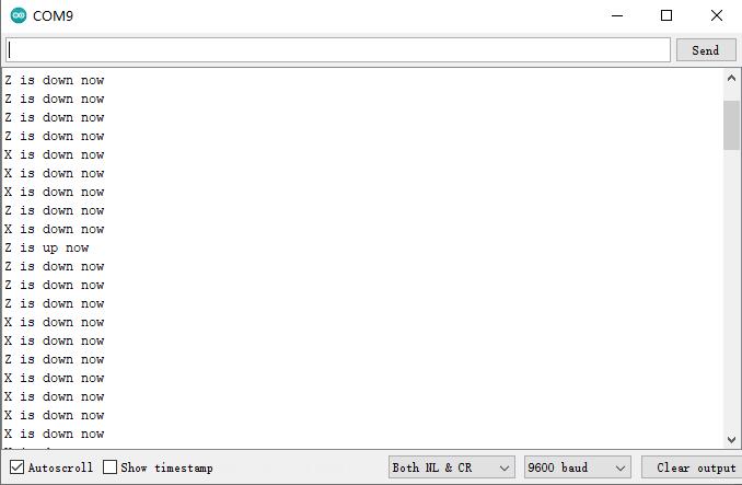
样例代码8-朝向检测功能(orientation.ino)
- 选择orientation.ino
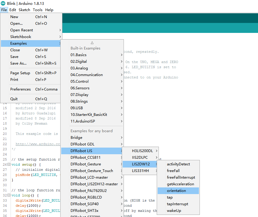
- 烧录程序
/**!
 * @file orientation.ino
 * @brief When detecting the orientation of the module, the sensor can detect the following six events:
 * @n Positive z-axis is facing up
 * @n Positive z-axis is facing down
 * @n Positive y-axis is facing up
 * @n Positive y-axis is facing down
 * @n Positive x-axis is facing up
 * @n Positive x-axis is facing down
 * @n When using SPI, chip select pin can be modified by changing the value of macro LIS2DW12_CS
 * @copyright  Copyright (c) 2010 DFRobot Co.Ltd (https://www.dfrobot.com)
 * @licence     The MIT License (MIT)
 * @author [fengli](li.feng@dfrobot.com)
 * @version  V1.0
 * @date  2021-01-16
 * @get from https://www.dfrobot.com
 * @https://github.com/DFRobot/DFRobot_LIS
 */
#include <DFRobot_LIS2DW12.h>

//When using I2C communication, use the following program to construct an object by DFRobot_LIS2DW12_I2C
/*!
 * @brief Constructor
 * @param pWire I2c controller
 * @param addr  I2C address(0x18/0x19)
 */
//DFRobot_LIS2DW12_I2C acce(&Wire,0x18);
DFRobot_LIS2DW12_I2C acce;


//When using SPI communication, use the following program to construct an object by DFRobot_LIS2DW12_SPI
#if defined(ESP32) || defined(ESP8266)
#define LIS2DW12_CS  D3
#elif defined(__AVR__) || defined(ARDUINO_SAM_ZERO)
#define LIS2DW12_CS 3
#elif (defined NRF5)
#define LIS2DW12_CS 2  //The pin on the development board with the corresponding silkscreen printed as P2
#endif
/*!
 * @brief Constructor
 * @param cs Chip selection pinChip selection pin
 * @param spi SPI controller
 */
//DFRobot_LIS2DW12_SPI acce(/*cs = */LIS2DW12_CS,&SPI);
//DFRobot_LIS2DW12_SPI acce(/*cs = */LIS2DW12_CS);

int lastOrientation = 0; //No event happened

void setup(void){

  Serial.begin(9600);
  while(!acce.begin()){
     Serial.println("Communication failed, check the connection and I2C address setting when using I2C communication.");
     delay(1000);
  }
  Serial.print("chip id : ");
  Serial.println(acce.getID(),HEX);
  //Chip soft reset
  acce.softReset();

  /**!
    Set the sensor measurement range:
                   e2_g   /<±2g>/
                   e4_g   /<±4g>/
                   e8_g   /<±8g>/
                   e16_g  /< ±16g>/
  */
  acce.setRange(DFRobot_LIS2DW12::e2_g);

  /**!
   Set power mode:
       eHighPerformance_14bit         /<High-Performance Mode,14-bit resolution>/
       eContLowPwr4_14bit             /<Continuous measurement,Low-Power Mode 4(14-bit resolution)>/
       eContLowPwr3_14bit             /<Continuous measurement,Low-Power Mode 3(14-bit resolution)>/
       eContLowPwr2_14bit             /<Continuous measurement,Low-Power Mode 2(14-bit resolution)/
       eContLowPwr1_12bit             /<Continuous measurement,Low-Power Mode 1(12-bit resolution)>/
       eSingleLowPwr4_14bit           /<Single data conversion on demand mode,Low-Power Mode 4(14-bit resolution)>/
       eSingleLowPwr3_14bit           /<Single data conversion on demand mode,Low-Power Mode 3(14-bit resolution)>/
       eSingleLowPwr2_14bit           /<Single data conversion on demand mode,Low-Power Mode 2(14-bit resolution)>/
       eSingleLowPwr1_12bit           /<Single data conversion on demand mode,Low-Power Mode 1(12-bit resolution)>/
       eHighPerformanceLowNoise_14bit /<High-Performance Mode,Low-noise enabled,14-bit resolution>/
       eContLowPwrLowNoise4_14bit     /<Continuous measurement,Low-Power Mode 4(14-bit resolution,Low-noise enabled)>/
       eContLowPwrLowNoise3_14bit     /<Continuous measurement,Low-Power Mode 3(14-bit resolution,Low-noise enabled)>/
       eContLowPwrLowNoise2_14bit     /<Continuous measurement,Low-Power Mode 2(14-bit resolution,Low-noise enabled)>/
       eContLowPwrLowNoise1_12bit     /<Continuous measurement,Low-Power Mode 1(12-bit resolution,Low-noise enabled)>/
       eSingleLowPwrLowNoise4_14bit   /<Single data conversion on demand mode,Low-Power Mode 4(14-bit resolution),Low-noise enabled>/
       eSingleLowPwrLowNoise3_14bit   /<Single data conversion on demand mode,Low-Power Mode 3(14-bit resolution),Low-noise enabled>/
       eSingleLowPwrLowNoise2_14bit   /<Single data conversion on demand mode,Low-Power Mode 2(14-bit resolution),Low-noise enabled>/
       eSingleLowPwrLowNoise1_12bit   /<Single data conversion on demand mode,Low-Power Mode 1(12-bit resolution),Low-noise enabled>/
  */
  acce.setPowerMode(DFRobot_LIS2DW12::eContLowPwrLowNoise1_12bit);

  /**!
    Set the sensor data collection rate:
               eRate_0hz           /<Measurement off>/
               eRate_1hz6          /<1.6hz, use only under low-power mode>/
               eRate_12hz5         /<12.5hz>/
               eRate_25hz
               eRate_50hz
               eRate_100hz
               eRate_200hz
               eRate_400hz       /<Use only under High-Performance mode>/
               eRate_800hz       /<Use only under High-Performance mode>/
               eRate_1k6hz       /<Use only under High-Performance mode>/
               eSetSwTrig        /<The software triggers a single measurement>/
  */
  acce.setDataRate(DFRobot_LIS2DW12::eRate_200hz);

  /**!
    Set the threshold of the angle when turning:
                     eDegrees80   (80°)
                     eDegrees70   (70°)
                     eDegrees60   (60°)
                     eDegrees50   (50°)
  */
  acce.set6DThreshold(DFRobot_LIS2DW12::eDegrees60);

  /**!
    Set the interrupt source of the int1 pin:
    eDoubleTap(Double click)
    eFreeFall(Free fall)
    eWakeUp(wake)
    eSingleTap(single-Click)
    e6D(Orientation change check)
  */
  acce.setInt1Event(DFRobot_LIS2DW12::e6D);

  delay(1000);
}

void loop(void){
    //check Changes detected in six directions
    if(acce.oriChangeDetected()){
        DFRobot_LIS2DW12::eOrient_t orientation = acce.getOrientation();
        if(lastOrientation != orientation){
            if(orientation == DFRobot_LIS2DW12::eXDown){
             Serial.println("X is down now");
            }
            if(orientation == DFRobot_LIS2DW12::eXUp){
             Serial.println("X is up now");
            }
            if(orientation == DFRobot_LIS2DW12::eYDown){
             Serial.println("Y is down now");
            }
            if(orientation == DFRobot_LIS2DW12::eYUp){
             Serial.println("Y is up now");
            }
            if(orientation == DFRobot_LIS2DW12::eZDown){
             Serial.println("Z is down now");
            }
            if(orientation == DFRobot_LIS2DW12::eZUp){
             Serial.println("Z is up now");
            }
            lastOrientation = orientation;
        }
    }
}
结果
树莓派使用教程
准备
-
硬件
- 树莓派4代B型(或类似)主控板 x 1
- LIS2DW12三轴加速度计 x 1
- 若干杜邦线 x 1
-
软件
接线图
- 将模块与树莓派按照连线图相连。I2C地址默认为0x19
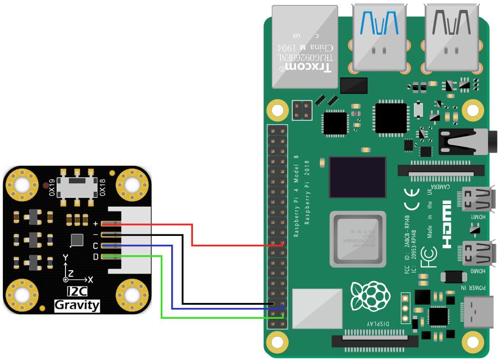
安装驱动
- 启动树莓派的I2C接口。如已开启,可跳过该步骤。
打开终端(Terminal),键入如下指令,并回车:
sudo raspi-config
然后用上下键选择“ 5 Interfacing Options ”, 按回车进入,选择 “ P5 I2C ”, 按回车确认“ YES ”即可。重启树莓派主控板。
- 安装Python依赖库与git,树莓派需要联网。如已安装,可跳过该步骤。
在终端中,依次键入如下指令,并回车:
sudo apt-get update
sudo apt-get install build-essential python-dev python-smbus git
- 下载LIS系列驱动库。在终端中,依次键入如下指令,并回车:
cd Desktop
git clone https://github.com/DFRobot/DFRobot_LIS
注意:
若您选择使用I2C(0X18)的通信方式,需要修改demo至相应的通信,您可能会遇到没有权限修改示例程序的情况,以下是解决办法:
1.在要修改的文件目录下查询权限,命令为:
ls -al
2.修改该文件权限,命令为:
sudo chmod a+w XXX.py
此时,所有人都对该文件具备写权限了。
样例代码
- 样例代码1-读取x,y,z轴加速度(get_acceleration.py)
- 样例代码2-睡眠唤醒功能(wake_up.py)
- 样例代码3-敲击检测功能(tap.py)
- 样例代码4-自由落体检测功能(free_fall.py)
- 样例代码5-自由落体中断功能(interrupt.py)(仅在Breakout版本可使用)
- 样例代码6-运动检测功能(activity_detect.py)
- 样例代码7-朝向检测功能(orientation.py)
样例代码1-读取x,y,z轴加速度(get_acceleration.py)
- 在终端中,键入如下指令并回车,运行样例代码:
cd home/pi/Desktop/DFRobot_LIS/python/raspberrypi/examples/LIS2DW12
cd get_acceleration
python get_acceleration.py
- 结果
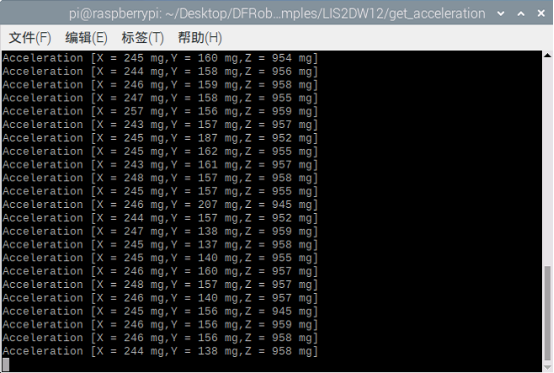
样例代码2-睡眠唤醒功能(wake_up.py)
- 在终端中,键入如下指令并回车,运行样例代码:
cd home/pi/Desktop/DFRobot_LIS/python/raspberrypi/examples/LIS2DW12
cd wake_up
python wake_up.py
- 结果

样例代码3-敲击检测功能(tap.py)
- 在终端中,键入如下指令并回车,运行样例代码:
cd home/pi/Desktop/DFRobot_LIS/python/raspberrypi/examples/LIS2DW12
cd tap
python tap.py
- 结果
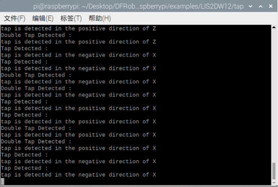
样例代码4-自由落体检测功能(free_fall.py)
- 在终端中,键入如下指令并回车,运行样例代码:
cd home/pi/Desktop/DFRobot_LIS/python/raspberrypi/examples/LIS2DW12
cd free_fall
python free_fall.py
- 结果
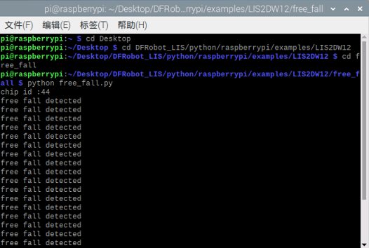
样例代码5-自由落体中断功能(interrupt.py)(仅在Breakout版本可使用)
- 在终端中,键入如下指令并回车,运行样例代码:
cd home/pi/Desktop/DFRobot_LIS/python/raspberrypi/examples/LIS2DW12
cd interrupt
python interrupt.py
样例代码6-运动检测功能(activity_detect.py)
- 在终端中,键入如下指令并回车,运行样例代码:
cd home/pi/Desktop/DFRobot_LIS/python/raspberrypi/examples/LIS2DW12
cd activity_detect
python activity_detect.py
- 结果
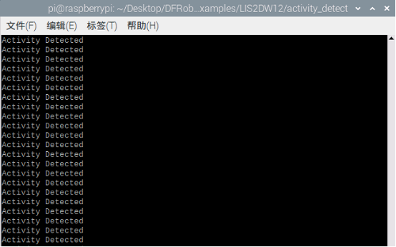
样例代码7-朝向检测功能(orientation.py)
- 在终端中,键入如下指令并回车,运行样例代码:
cd home/pi/Desktop/DFRobot_LIS/python/raspberrypi/examples/LIS2DW12
cd orientation
python orientation.py
- 结果
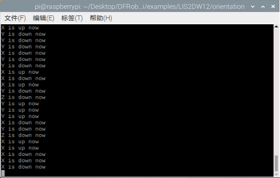
常见问题
如果有客户对此产品有任何问题,欢迎通过qq或者论坛联系我们!
更多问题及有趣的应用,可以 访问论坛 进行查阅或发帖。

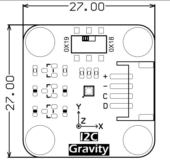