概述
红外定位摄像头可追踪4个移动的红外点,分辨率是1024 X 768。红外定位摄像头,具有高分辨率,高灵敏度,高精确度的优点,同时有体积小、重量轻、方便安装的特点。可以广泛应用在机器人自动寻源装置、机器人足球比赛、移动轨迹识别等各种需要定点定位的地方。红外定位摄像头可以通过arduino等各种具有I2C接口的控制器通过串口连接到processing上面,实时的显示出检测到的目标的坐标位置及数值。不要感觉这些是很不可思议的事情,强大的红外摄像头还具有更多好玩的功能,可以和processing做出各种各样的互动产品,只要你是喜欢玩的人、肯花心思思考这些都可以轻松实现。
参数
1、工作电压:5V、3.3V
2、检测距离:0~3m
3、接口:I2C接口
4、不同距离可检测的范围
距离(cm)——水平距离(cm)—— 垂直距离(cm)
10(cm)————8.5(cm)————7.5(cm)
50(cm)————42(cm)—————32(cm)
100(cm)———70(cm)——————60(cm)
注:其他距离规律相同。
引脚定义
1、红线:接电源5V或者3.3V
2、黑线:接地
3、黄线:SDA
4、绿线:SCL
功能描述
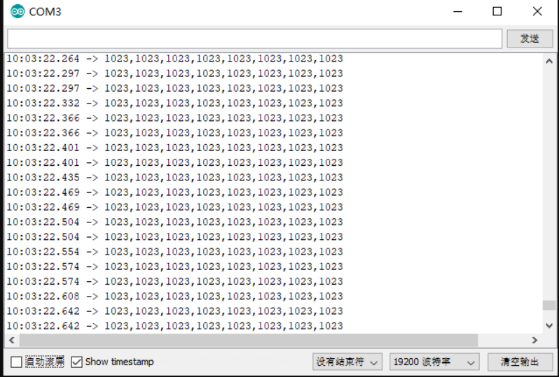
红外定位摄像头可以用arduino、AVR等各种有I2C接口的控制器控制。最多可以追踪4个移动的红外点,并且把这些数据提供给主机。水平视角是33度,垂直视角是23度。一次返回四个点的坐标,当红外定位摄像头识别一个对象。它相应的坐标就是在第一组坐标位置,其他坐标位置为空(返回1023,1023)。如果识别多个目标则,按照检测到的先后顺序依次排列,如果其中有的运动目标移动出了视野,则相应的位置为空(返回1023,1023)。其余坐标位置保持不变。
与Arduino ide互动
准备
- 硬件
- 1 x Arduino UNO控制板
- 1 x 红外定位探头
- 软件
- Arduino IDE, 点击下载Arduino IDE
- 示例代码
// Wii Remote IR sensor  test sample code  by kako https://www.kako.com
// modified output for Wii-BlobTrack program by RobotFreak https://www.letsmakerobots.com/user/1433
// modified for https://DFRobot.com by Lumi, Jan. 2014
#include <Wire.h>
	int IRsensorAddress = 0xB0;
	//int IRsensorAddress = 0x58;
	int slaveAddress;
	int ledPin = 13;
	boolean ledState = false;
	byte data_buf[16];
	int i;

	int Ix[4];
	int Iy[4];
	int s;

	void Write_2bytes(byte d1, byte d2)
	{
		Wire.beginTransmission(slaveAddress);
		Wire.write(d1); Wire.write(d2);
		Wire.endTransmission();
	}

	void setup()
	{
		slaveAddress = IRsensorAddress >> 1;   // This results in 0x21 as the address to pass to TWI
		Serial.begin(19200);
		pinMode(ledPin, OUTPUT);      // Set the LED pin as output
		Wire.begin();
		// IR sensor initialize
		Write_2bytes(0x30,0x01); delay(10);
		Write_2bytes(0x30,0x08); delay(10);
		Write_2bytes(0x06,0x90); delay(10);
		Write_2bytes(0x08,0xC0); delay(10);
		Write_2bytes(0x1A,0x40); delay(10);
		Write_2bytes(0x33,0x33); delay(10);
		delay(100);
	}
	void loop()
	{
		ledState = !ledState;
		if (ledState) { digitalWrite(ledPin,HIGH); } else { digitalWrite(ledPin,LOW); }

		//IR sensor read
		Wire.beginTransmission(slaveAddress);
		Wire.write(0x36);
		Wire.endTransmission();

		Wire.requestFrom(slaveAddress, 16);        // Request the 2 byte heading (MSB comes first)
		for (i=0;i<16;i++) { data_buf[i]=0; }
		i=0;
		while(Wire.available() && i < 16) {
			data_buf[i] = Wire.read();
			i++;
		}

		Ix[0] = data_buf[1];
		Iy[0] = data_buf[2];
		s   = data_buf[3];
		Ix[0] += (s & 0x30) <<4;
		Iy[0] += (s & 0xC0) <<2;

		Ix[1] = data_buf[4];
		Iy[1] = data_buf[5];
		s   = data_buf[6];
		Ix[1] += (s & 0x30) <<4;
		Iy[1] += (s & 0xC0) <<2;

		Ix[2] = data_buf[7];
		Iy[2] = data_buf[8];
		s   = data_buf[9];
		Ix[2] += (s & 0x30) <<4;
		Iy[2] += (s & 0xC0) <<2;

		Ix[3] = data_buf[10];
		Iy[3] = data_buf[11];
		s   = data_buf[12];
		Ix[3] += (s & 0x30) <<4;
		Iy[3] += (s & 0xC0) <<2;

		for(i=0; i<4; i++)
		{
		  if (Ix[i] < 1000)
			Serial.print("");
		  if (Ix[i] < 100)
			Serial.print("");
		  if (Ix[i] < 10)
			Serial.print("");
		  Serial.print( int(Ix[i]) );
		  Serial.print(",");
		  if (Iy[i] < 1000)
			Serial.print("");
		  if (Iy[i] < 100)
			Serial.print("");
		  if (Iy[i] < 10)
			Serial.print("");
		  Serial.print( int(Iy[i]) );
		  if (i<3)
			Serial.print(",");
		}
		Serial.println("");
		delay(15);
	}
打开Arduino IDE,复制提供的示例代码,连接对应的端口,上传到UNO主板上:
运行结果示例如下:
与Processing互动
准备
- 硬件
- 1 x Arduino UNO控制板
- 1 x 红外定位探头
- 1 x 数字红外信号发射模块
- 软件
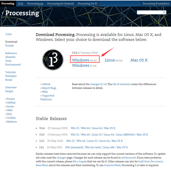
- Processing, 点击下载Processing
- 大家根据自己的系统选择对应的安装包。
- 下载安装包,并且解压。
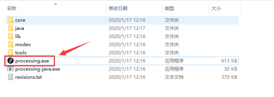
- 打开软件
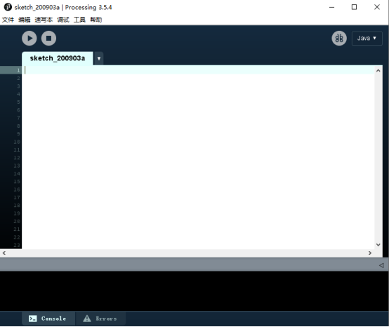
- 示例代码(将代码复制到Processing中)
	import processing.serial.*;

	int lf = 10;    // Linefeed in ASCII
	String myString = null;
	Serial myPort;  // The serial port

	void setup() {
	  // List all the available serial ports
	  //println(Serial.list());
	  // Open the port you are using at the rate you want:
	  myPort = new Serial(this, Serial.list()[0], 19200);
	  myPort.clear();
	  // Throw out the first reading, in case we started reading
	  // in the middle of a string from the sender.
	  myString = myPort.readStringUntil(lf);
	  myString = null;
	  size(800,800);
	  //frameRate(30);
	}

	void draw() {
	  background(77);
		myString = myPort.readStringUntil(lf);
		if (myString != null) {
		  int[] output = int (split(myString, ','));
		if(output.length!=8)
		  return;
		  println(myString); // display the incoming string

		  int xx = output[0];
		  int yy = output[1];

		  int ww = output[2];
		  int zz = output[3];

		  int xxx = output[4];
		  int yyy = output[5];

		  int www = output[6];
		  int zzz = output[7];

		  ellipseMode(RADIUS);  // Set ellipseMode to RADIUS
		  fill(255, 0, 0);  // Set fill to red
		  ellipse(xx, yy, 20, 20);
		  ellipseMode(RADIUS);  // Set ellipseMode to RADIUS
		  fill(0, 255, 0);  // Set fill to green
		  ellipse(ww, zz, 20, 20);

		  ellipseMode(RADIUS);  // Set ellipseMode to RADIUS
		  fill(0, 0, 255);  // Set fill to blue
		  ellipse(xxx, yyy, 20, 20);
		  ellipseMode(RADIUS);  // Set ellipseMode to RADIUS
		  fill(255);  // Set fill to white
		  ellipse(www, zzz, 20, 20);

		}
	}
- 注意:
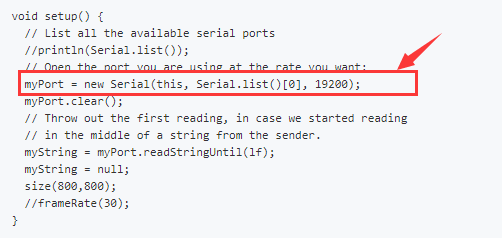
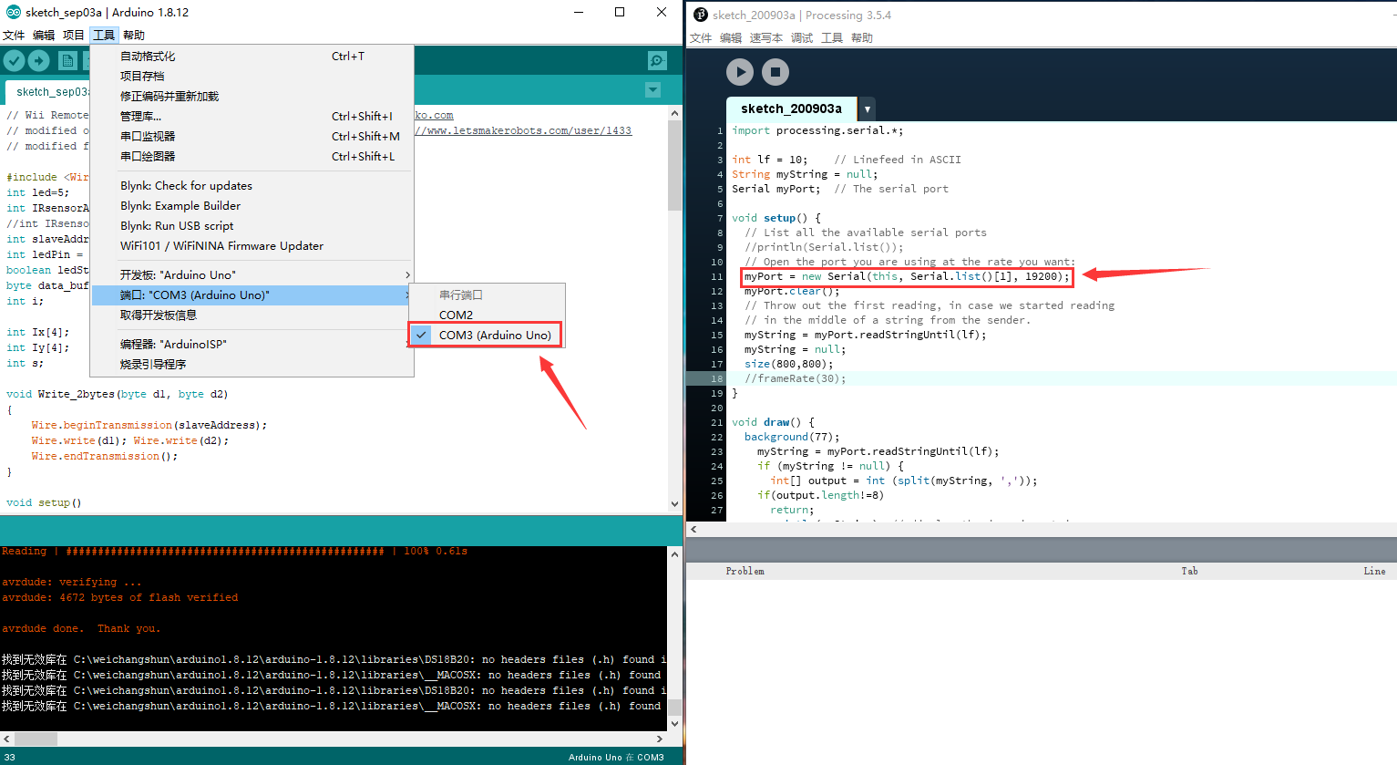
这里需要根据Arduino IDE中的端口顺序进行调整,如果在Arduino IDE中 ,主板的端口位于第一位,这里的索引就为0;如果在Arduino IDE中,读出的主板端口位于第二位(如图所示,显示的COM3),就需要把索引调整为1:
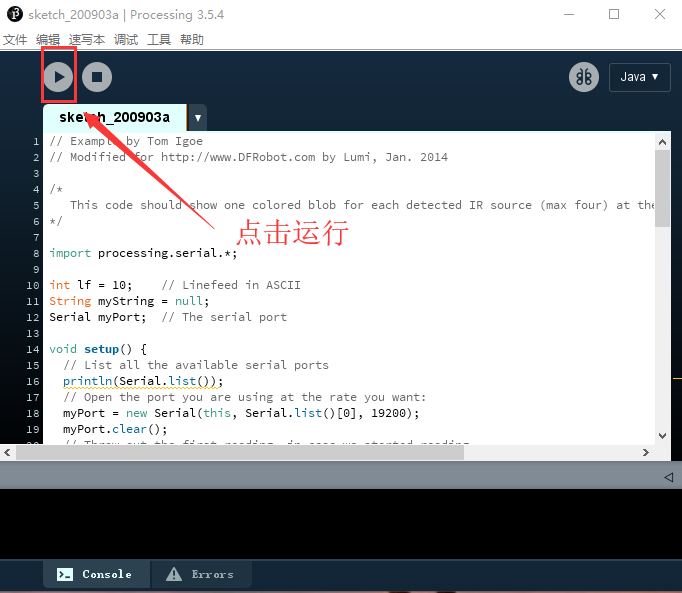
点击运行:
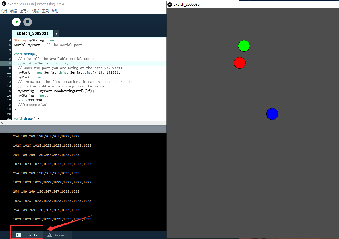
运行结果:
点击“console”,可以看到窗口打印的数据
常见问题
为什么可以在显示栏发现多个点?
主要的原因是由于在使用数字红外信号发射模块的时候,
会受到由于器件摆放方式不同,产生反射,折射等物理现象就会在processing中显示多个点,并且波动比较大。
验证这一问题的方法就是使用一个能发送单一的红外信号,如此就只会在processing中产生一个红外斑点。
比如,我们可以使用红外遥控器,就能发送单一的信号源。
Mind+图形化编程
1、下载及安装软件。下载地址:https://mindplus.cc 详细教程:安装教程
2、切换到“上传模式”。 详细教程:Mind+基础wiki教程-上传模式编程流程
3、“扩展”中选择“主控板”中的“Arduino Uno”。用户库中搜索红外定位加载扩展库。 详细教程:Mind+基础wiki教程-加载扩展库流程
4、进行编程,程序如下图:
5、菜单“连接设备”,“上传到设备”
6、程序上传完毕后,打开串口即可看到数据输出。详细教程:Mind+基础wiki教程-串口打印

 购买
购买