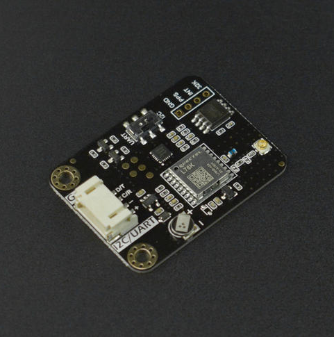
简介
该产品是一款集成了GNSS和RTC芯片的模块。可接收北斗、GPS等多种卫星信号,获取准确的时间信息,并为RTC校时,以确保时间的高精度和稳定性。它为用户提供了一种简单、便捷的方式来校准和维护设备的时间,适用于各种需要精确时间同步的应用场景。
在无法获取GNSS信号的情况下,可以使用板载的RTC芯片获取时间。
当在户外需要低功耗的的场景中,也可以通过API切断GNSS的供电来大幅降低功耗。
产品参数
-
工作电压: 3.3V~5V DC
-
输出信号:I2C/UART
-
定位精度:2.0m CEP
-
首次定位时间:冷启动30S 热启动2S
-
功耗:46mA(GNSS芯片开启), <1mA (GNSS芯片关闭)。以上均为5V状况测试。
-
天线接口: IPEX一代
-
产品尺寸:32mm * 42mm
引脚说明
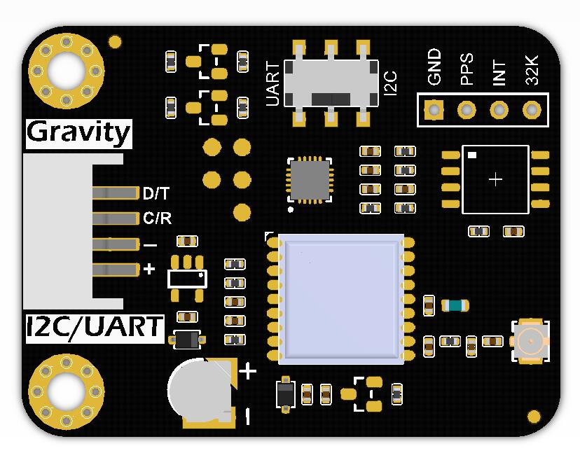
| 标号 | 名称 | 功能描述 |
|---|---|---|
| 1 | D/T | I2C数据线SDA UART数据传输-TX |
| 2 | C/R | I2C时钟线SCL UART数据接收-RX |
| 3 | - | GND电源负极 |
| 4 | + | 电源正极 |
| 5 | PPS | GNSS芯片每秒脉冲输出 |
| 6 | INT | 低电平有效中断或者1Hz方波输出 |
| 7 | 32K | 32.768KHz脉冲输出 |
Arduino使用教程
一、软硬件准备
-
硬件
-
软件
- Arduino IDE 点击下载Arduino IDE
- 下载并安装DFRobot_GNSS and RTC库
-
接线图

样例代码 1 - 获取GNSS定位
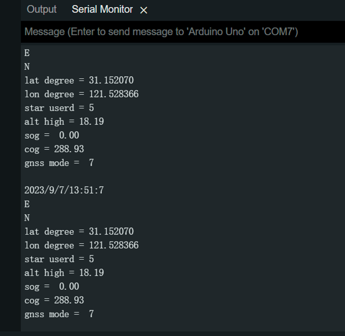
调用所有GNSS相关API,获得经纬度,卫星数量,卫星数量等参数。
示例代码为I2C通讯。
/*!
 * @file  getGNSS.ino
 * @brief Get gnss simple data
 * @copyright Copyright (c) 2010 DFRobot Co.Ltd (http://www.dfrobot.com)
 * @license The MIT License (MIT)
 * @author [qsjhyy](yihuan.huang@dfrobot.com)
 * @version V1.0
 * @date 2022-08-30
 * @url https://github.com/DFRobot/DFRobot_GNSSAndRTC
 */

#include "DFRobot_GNSSAndRTC.h"

#define I2C_COMMUNICATION  //use I2C for communication, but use the serial port for communication if the line of codes were masked

#ifdef  I2C_COMMUNICATION
DFRobot_GNSSAndRTC_I2C gnss(&Wire, MODULE_I2C_ADDRESS);
#else
 /* ---------------------------------------------------------------------------------------------------------------------
  *    board   |             MCU                | Leonardo/Mega2560/M0 |    UNO    | ESP8266 | ESP32 |  microbit  |   m0  |
  *     VCC    |            3.3V/5V             |        VCC           |    VCC    |   VCC   |  VCC  |     X      |  vcc  |
  *     GND    |              GND               |        GND           |    GND    |   GND   |  GND  |     X      |  gnd  |
  *     RX     |              TX                |     Serial1 TX1      |     5     |   5/D6  |  D2   |     X      |  tx1  |
  *     TX     |              RX                |     Serial1 RX1      |     4     |   4/D7  |  D3   |     X      |  rx1  |
  * ----------------------------------------------------------------------------------------------------------------------*/
  /* Baud rate cannot be changed */
#if defined(ARDUINO_AVR_UNO) || defined(ESP8266)
SoftwareSerial mySerial(4, 5);
DFRobot_GNSSAndRTC_UART gnss(&mySerial, UART_BAUDRATE);
#elif defined(ESP32)
DFRobot_GNSSAndRTC_UART gnss(&Serial1, UART_BAUDRATE,/*rx*/D2,/*tx*/D3);
#else
DFRobot_GNSSAndRTC_UART gnss(&Serial1, UART_BAUDRATE);
#endif
#endif

void setup()
{
	Serial.begin(115200);
	while (!gnss.begin()) {
		Serial.println("NO Deivces !");
		delay(1000);
}

	gnss.enablePower();      // Enable gnss power

	/** Set GNSS to be used
	 *   eGPS              use gps
	 *   eBeiDou           use beidou
	 *   eGPS_BeiDou       use gps + beidou
	 *   eGLONASS          use glonass
	 *   eGPS_GLONASS      use gps + glonass
	 *   eBeiDou_GLONASS   use beidou +glonass
	 *   eGPS_BeiDou_GLONASS use gps + beidou + glonass
	 */
	gnss.setGnss(gnss.eGPS_BeiDou_GLONASS);

	// gnss.disablePower();      // Disable GNSS, the data will not be refreshed after disabling
}

void loop()
{
	DFRobot_GNSSAndRTC::sTim_t utc = gnss.getUTC();
	DFRobot_GNSSAndRTC::sTim_t date = gnss.getDate();
	DFRobot_GNSSAndRTC::sLonLat_t lat = gnss.getLat();
	DFRobot_GNSSAndRTC::sLonLat_t lon = gnss.getLon();
	double high = gnss.getAlt();
	uint8_t starUserd = gnss.getNumSatUsed();
	double sog = gnss.getSog();
	double cog = gnss.getCog();

	Serial.println("");
	Serial.print(date.year);
	Serial.print("/");
	Serial.print(date.month);
	Serial.print("/");
	Serial.print(date.date);
	Serial.print("/");
	Serial.print(utc.hour);
	Serial.print(":");
	Serial.print(utc.minute);
	Serial.print(":");
	Serial.print(utc.second);
	Serial.println();
	Serial.println((char)lat.latDirection);
	Serial.println((char)lon.lonDirection);

	// Serial.print("lat DDMM.MMMMM = ");
	// Serial.println(lat.latitude, 5);
	// Serial.print("lon DDDMM.MMMMM = ");
	// Serial.println(lon.lonitude, 5);
	Serial.print("lat degree = ");
	Serial.println(lat.latitudeDegree, 6);
	Serial.print("lon degree = ");
	Serial.println(lon.lonitudeDegree, 6);

	Serial.print("star userd = ");
	Serial.println(starUserd);
	Serial.print("alt high = ");
	Serial.println(high);
	Serial.print("sog =  ");
	Serial.println(sog);
	Serial.print("cog = ");
	Serial.println(cog);
	Serial.print("gnss mode =  ");
	Serial.println(gnss.getGnssMode());
	delay(1000);
}
结果
样例代码 2 - 获取RTC时间
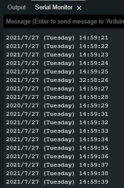
获取授时模块板载RTC芯片的时间。
此示例代码为I2C通讯
/*!
* @file getTime.ino
* @brief Run this routine, set internal clock first, and then circularly get clock, temperature and voltage data
* @copyright    Copyright (c) 2010 DFRobot Co.Ltd (http://www.dfrobot.com)
* @license      The MIT License (MIT)
* @author [qsjhyy](yihuan.huang@dfrobot.com)
* @version V1.0
* @date 2022-08-30
* @url https://github.com/DFRobot/DFRobot_GNSSAndRTC
*/
#include "DFRobot_GNSSAndRTC.h"

#define I2C_COMMUNICATION  //use I2C for communication, but use the serial port for communication if the line of codes were masked

#ifdef  I2C_COMMUNICATION
DFRobot_GNSSAndRTC_I2C rtc(&Wire, MODULE_I2C_ADDRESS);
#else
/* ---------------------------------------------------------------------------------------------------------------------
    *    board   |             MCU                | Leonardo/Mega2560/M0 |    UNO    | ESP8266 | ESP32 |  microbit  |   m0  |
    *     VCC    |            3.3V/5V             |        VCC           |    VCC    |   VCC   |  VCC  |     X      |  vcc  |
    *     GND    |              GND               |        GND           |    GND    |   GND   |  GND  |     X      |  gnd  |
    *     RX     |              TX                |     Serial1 TX1      |     5     |   5/D6  |  D2   |     X      |  tx1  |
    *     TX     |              RX                |     Serial1 RX1      |     4     |   4/D7  |  D3   |     X      |  rx1  |
    * ----------------------------------------------------------------------------------------------------------------------*/
/* Baud rate cannot be changed  */
#if defined(ARDUINO_AVR_UNO) || defined(ESP8266)
SoftwareSerial mySerial(4, 5);
DFRobot_GNSSAndRTC_UART rtc(&mySerial, UART_BAUDRATE);
#elif defined(ESP32)
DFRobot_GNSSAndRTC_UART rtc(&Serial1, UART_BAUDRATE,/*rx*/D2,/*tx*/D3);
#else
DFRobot_GNSSAndRTC_UART rtc(&Serial1, UART_BAUDRATE);
#endif
#endif

void setup()
{
  Serial.begin(115200);
  /*Wait for the chip to be initialized completely, and then exit*/
  while(!rtc.begin()){
  	Serial.println("Failed to init chip, please check if the chip connection is fine. ");
  	delay(1000);
  }
  rtc.setHourSystem(rtc.e24hours);//Set display format
  rtc.setTime(2021,7,27,14,59,0);//Initialize time
  // //Get internal temperature
  // Serial.print(rtc.getTemperatureC());
  // Serial.println(" C");
  // //Get battery voltage
  // Serial.print(rtc.getVoltage());
  // Serial.println(" V");
}

void loop()
{
  DFRobot_GNSSAndRTC::sTimeData_t sTime;
  sTime = rtc.getRTCTime();
  Serial.print(sTime.year, DEC);//year
  Serial.print('/');
  Serial.print(sTime.month, DEC);//month
  Serial.print('/');
  Serial.print(sTime.day, DEC);//day
  Serial.print(" (");
  Serial.print(sTime.week);//week
  Serial.print(") ");
  Serial.print(sTime.hour, DEC);//hour
  Serial.print(':');
  Serial.print(sTime.minute, DEC);//minute
  Serial.print(':');
  Serial.print(sTime.second, DEC);//second
  Serial.println(' ');
  /*Enable 12-hour time format*/
  // Serial.print(rtc.getAMorPM());
  // Serial.println();
  delay(1000);
}
结果
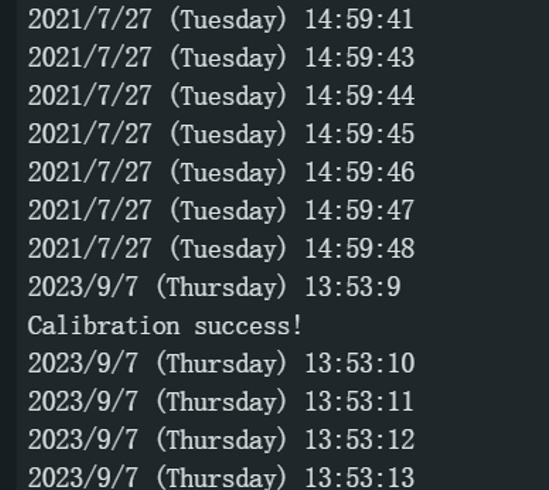
样例代码 3 - GNSS校准RTC时间
通过GNSS时间来校准RTC芯片。校时过程需要2~3秒,这段时间内无法正常获取时间。
校时完成后串行监视器打印"Calibration success"。
此示例代码为I2C通讯
/*!
 * @file gnssCalibRTC.ino
 * @brief Run this routine, calibration internal clock first, and then circularly get clock
 * @copyright    Copyright (c) 2010 DFRobot Co.Ltd (http://www.dfrobot.com)
 * @license      The MIT License (MIT)
 * @author [qsjhyy](yihuan.huang@dfrobot.com)
 * @version V1.0
 * @date 2022-08-30
 * @url https://github.com/DFRobot/DFRobot_GNSSAndRTC
 */
#include "DFRobot_GNSSAndRTC.h"

#define I2C_COMMUNICATION  //use I2C for communication, but use the serial port for communication if the line of codes were masked

#ifdef  I2C_COMMUNICATION
DFRobot_GNSSAndRTC_I2C rtc(&Wire, MODULE_I2C_ADDRESS);
#else
/* ---------------------------------------------------------------------------------------------------------------------
      *    board   |             MCU                | Leonardo/Mega2560/M0 |    UNO    | ESP8266 | ESP32 |  microbit  |   m0  |
      *     VCC    |            3.3V/5V             |        VCC           |    VCC    |   VCC   |  VCC  |     X      |  vcc  |
      *     GND    |              GND               |        GND           |    GND    |   GND   |  GND  |     X      |  gnd  |
      *     RX     |              TX                |     Serial1 TX1      |     5     |   5/D6  |  D2   |     X      |  tx1  |
      *     TX     |              RX                |     Serial1 RX1      |     4     |   4/D7  |  D3   |     X      |  rx1  |
* ----------------------------------------------------------------------------------------------------------------------*/
/* Baud rate cannot be changed  */
#if defined(ARDUINO_AVR_UNO) || defined(ESP8266)
SoftwareSerial mySerial(4, 5);
DFRobot_GNSSAndRTC_UART rtc(&mySerial, UART_BAUDRATE);
#elif defined(ESP32)
DFRobot_GNSSAndRTC_UART rtc(&Serial1, UART_BAUDRATE,/*rx*/D2,/*tx*/D3);
#else
DFRobot_GNSSAndRTC_UART rtc(&Serial1, UART_BAUDRATE);
#endif
#endif

void setup()
{
	Serial.begin(115200);
	/*Wait for the chip to be initialized completely, and then exit*/
	while (!rtc.begin()) {
		Serial.println("Failed to init chip, please check if the chip connection is fine. ");
		delay(1000);
	}
	rtc.setHourSystem(rtc.e24hours);//Set display format

	/**
	 * @brief Calibrate RTC immediately with GNSS
	 * @note This is a single calibration;
	 * @n If the GNSS module signal is weak, time calibration may encounter issues.
	 * @return None
	 */
	// rtc.calibRTC();

	/**
	* @brief The loop automatically performs GNSS timing based on the set interval
	* @param hour Automatic calibration of the time interval. range: 0~255, unit: hour.
	* @note When set to zero, automatic time calibration is disabled.
	* @n Enabling it will trigger an immediate calibration.
	* @n If the GNSS module signal is weak, time calibration may encounter issues.
	* @return None
	*/
	rtc.calibRTC(1);
}
	uint8_t underCalibCount = 0;

void loop()
{
	/**
	* @brief Current clock calibration status
	* @param mode By default, it is set to true, indicating access to the calibration status only.
	* @n  If continuous calibration for one minute does not return a successful calibration,
	* @n  you can pass in false to manually terminate this calibration session.
	* @return uint8_t type, indicates current clock calibration status
	* @retval 0 Not calibrated
	* @retval 1 Calibration complete
	* @retval 2 Under calibration
	* @note Note: To avoid affecting subsequent calibration status,
	* @n    "Calibration completed Status (1)" is automatically zeroed after a successful read
	*/
	uint8_t status = rtc.calibStatus();
	if (DFRobot_GNSSAndRTC::eCalibComplete == status) {
		underCalibCount = 0;
		Serial.println("Calibration success!");
	} else if (DFRobot_GNSSAndRTC::eUnderCalib == status) {
		underCalibCount += 1;
		if (60 <= underCalibCount) {   // If the calibration fails for a long time, manually terminate the calibration
			rtc.calibStatus(false);
			underCalibCount = 0;
			Serial.println("Calibration failed!");
			Serial.println("It may be due to weak satellite signals.");
			Serial.println("Please proceed to an open outdoor area for time synchronization.");
		}
	}
	DFRobot_GNSSAndRTC::sTimeData_t sTime;
	sTime = rtc.getRTCTime();
	Serial.print(sTime.year, DEC);//year
	Serial.print('/');
	Serial.print(sTime.month, DEC);//month
	Serial.print('/');
	Serial.print(sTime.day, DEC);//day
	Serial.print(" (");
	Serial.print(sTime.week);//week
	Serial.print(") ");
	Serial.print(sTime.hour, DEC);//hour
	Serial.print(':');
	Serial.print(sTime.minute, DEC);//minute
	Serial.print(':');
	Serial.print(sTime.second, DEC);//second
	Serial.println(' ');
	/*Enable 12-hour time format*/
	// Serial.print(rtc.getAMorPM());
	// Serial.println();

	// In addition to data acquisition and other time consuming, the delay of 900ms makes each loop closer to 1 second
	delay(900);
}
结果
更多API接口函数列表
  /**
   * @fn calibRTC(void)
   * @brief 立即使用GNSS来校准RTC时钟
   * @note This is a single calibration;
   * @n If the GNSS module signal is weak, time calibration may encounter issues.
   * @return None
   */
      void calibRTC(void);

  /**
   * @fn calibRTC(uint8_t hour)
   * @brief 根据设定的时间间隔自动执行 GNSS 校准 RTC
   * @param hour Automatic calibration of the time interval. range: 0~255, unit: hour.
   * @note When set to zero, automatic time calibration is disabled.
   * @n Enabling it will trigger an immediate calibration.
   * @n If the GNSS module signal is weak, time calibration may encounter issues.
   * @return None
   */
      void calibRTC(uint8_t hour);

  /**
   * @fn calibStatus
   * @brief 获取校准状态
   * @param mode By default, it is set to true, indicating access to the calibration status only.
   * @n  If continuous calibration for one minute does not return a successful calibration,
   * @n  you can pass in false to manually terminate this calibration session.
   * @return uint8_t type, indicates current clock calibration status
   * @retval 0 Not calibrated
   * @retval 1 Calibration complete
   * @retval 2 Under calibration
   * @note Note: To avoid affecting subsequent calibration status,
   * @n    "Calibration completed Status (1)" is automatically zeroed after a successful read
   */
     uint8_t calibStatus(bool mode = true);

  /**
   * @fn setAlarm
   * @brief 设置报警时间
   * @param year 2000~2099
   * @param month 1~12
   * @param day 1~31
   * @return None
   */
    void setAlarm(uint16_t year, uint8_t month, uint8_t day);

  /**
   * @brief 清除报警
   */
    void clearAlarm(void);

  /**
   * @fn enable32k
   * @brief 使能32kHz方波输出
   * @return None
   */
   void enable32k();


  /**
   * @fn disable32k
   * @brief 失能32kHz方波输出
   * @return None
   */
   void disable32k();

  /**
   * @fn countDown
   * @brief 倒计时
   * @param second  countdown time 0-0xffffff
   */
   void countDown(uint32_t second);

  /**
   * @fn getUTC
   * @brief 获取UTC时间
   * @return sTim_t type, represents the returned hour, minute and second
   * @retval sTim_t.hour hour
   * @retval sTim_t.minute minute
   * @retval sTim_t.second second
   */
    sTim_t getUTC(void);


  /**
   * @fn enablePower
   * @brief 使能GNSS电源
   * @return null
   */
   void enablePower(void);

  /**
   * @fn disablePower
   * @brief 失能GNSS电源
   * @return null
   */
   void disablePower(void);
Mind+ 上传模式编程
1.下载及安装软件。下载地址:https://www.mindplus.cc
2.切换到“上传模式”。
3.“扩展”中选择“主控板”中的“Arduino UNO”。用户库加载:https://gitee.com/chenqi1233/ext-gravity-gnss-pt
4.进行编程,程序如下图
5.菜单“链接设备”,“上传到设备”
6.程序上传完毕后,打开串口即可看到数据输出。

常见问题
-
Q1校准RTC芯片过,但是断电后读取RTC,发现时间不正确
A1.RTC芯片需要消耗电量来维持时间,我们板载设计了超级电容在整个模块断电时为其提供电量。
经过测试,超级电容中的电量会在模块断电后10~20分钟左右耗尽。
所以在断电后,RTC时间仅能维持10~20分钟。
我们建议您在重新为其上电的时候用GNSS芯片校准一次RTC时间。 -
Q2 校准时间后,发现小时读数不正确
A2.卫星校准时间是使用UTC时间的,国内的北京时间需要UTC+8小时。
