1. 产品简介
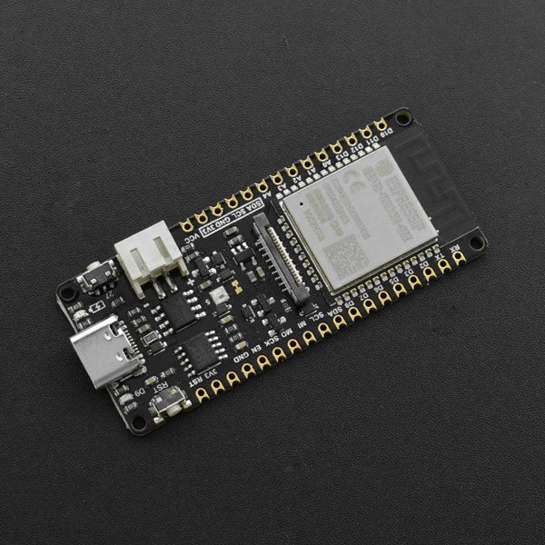
FireBeetle 2 ESP32-E是一款基于ESP-WROOM-32E双核芯片的主控板,它专为IoT设计。它支持WIFI和蓝牙双模通信,并具有体积小巧、超低功耗、板载充电电路、接口易用等特性。可灵活的用于家庭物联网改装、工业物联网改装、可穿戴设备等等。通过和IFTTT等物联网平台的连接,你可轻松制作出你独有的特色物联网智能家居系统。
FireBeetle 2 ESP32-E支持Arduino IDE编程,并且即将支持Scratch图形化编程及MicroPython编程。我们提供了的在线教程和应用案例,以及上千种免焊接的Gravity接口传感器与执行器,可轻松上手制作,大幅度降低你的学习时间。邮票孔的设计,让它可以方便的嵌入你设计的PCB上,大大缩减你的原型开发成本以及原型测试时间。
2. FireBeetle系列是什么
FireBeetle是一个高性能且更mini的Arduino开源开发板系列,现在FireBeetle不仅完全兼容arduino的开发环境,并且拥有更丰富的软硬件资源,它将支持makecode、Mind+、pinpong、MicroPython的开发环境(即将完善),无论是图形化编程、C语言、python编程还是JS编程都可以随心所欲的操作硬件。
它是如此的灵活并且开源,我们为您提供了最简单的编程方式!最详细的教程资料!上千种易用的Gravity外设!无论您是学生、电子爱好者、艺术家或者设计师,它都将是您开启电子世界的最佳伙伴,不用再面对复杂的电路、烧脑的程序、五花八门的通信协议。
3. 产品特性
- DFRobot FireBeetle V2系列兼容,体积小巧仅25.4 × 60 mm
- ESP32双核低功耗主控,WiFi+BT4.0二合一
- GDI显示接口,单线连接显示屏
- 板载充电电路以及PH2.0锂电池接口
4. 性能描述
- 电源参数
- 输入电压
- USB-C接口:5V DC
- PH2.0接口:3.7~4.2V Li-ion
- VCC引脚:5V DC
- 输入电压
- MCU参数
- 处理器:Xtensa 双核32位LX6微处理器
- 主频:240 MHz
- SRAM:520 KB
- ROM:448 KB
- Flash:4 MB
- 无线参数
- Wi-Fi协议:
- IEEE 802.11 b/g/n (802.11n模式下数据速率高达150 Mbps)
- 支持 A-MPDU 和 A-MSDU 聚合
- 支持0.4 μs防护间隔
- 工作信道中心频率范围:2412~2484 MHz
- 蓝牙协议:
- 蓝牙V4.2 BR/EDR 和蓝牙 LE 标准
- 蓝牙CVSD和SBC音频
- 蓝牙频率范围:2402~2480 MHz
- Wi-Fi协议:
- 外设参数
- 数字引脚×18:IO0、IO1、IO2、IO3、IO4、IO12、IO13、IO14、IO15、IO16、IO17、IO18、IO19、IO21、IO22、IO23、IO25、IO26
- 模拟引脚×11:IO0、IO2、IO4、IO12、IO13、IO14、IO15、IO25、IO26、I34、I35
- URAT接口:×2
- SPI接口:×1
- I2C接口 :×1
- I2S 接口:×1
- DAC 接口:×2
- 触摸接口:×7
- LED PWM通道:×16
- RGB_LED:WS2812
- 显示接口:GDI
- 其他参数
- 模块尺寸:25.4mm × 60mm
- 安装孔尺寸:孔径2.0mm
- 重量:23g
5. 外观指示图

| 序号 | 功能名称 | 功能说明 |
|---|---|---|
| ① | USB接口 | 下载程序及供电接口,支持4.75V~5.5V |
| ② | 充电指示灯 | 指示充电状态的红色LED灯,通过三种方式指示充电状态:1、充满电或未充电时熄灭;2、充电时常亮;3、USB供电,未连接锂电池时高频闪烁 |
| ③ | 用户按钮 | 使用IO27/D4引脚控制该按钮 |
| ④ | 锂电池接口 | 支持3.7V~4.2V |
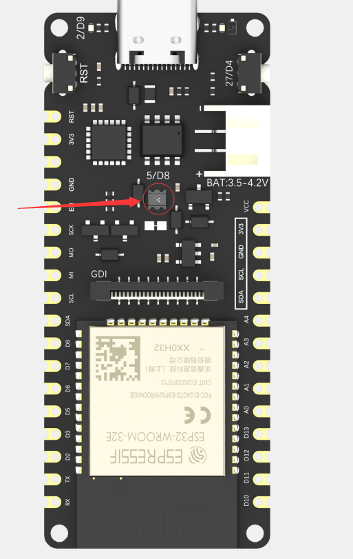
| ⑤ | 板载RGB灯 | 使用IO5/D8引脚控制的WS2812 RGB灯珠 |
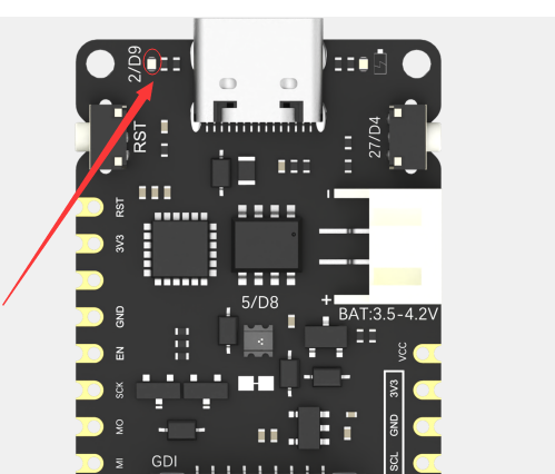
| ⑥ | 板载LED灯 | 使用IO2/D9引脚控制的LED灯 |
| ⑦ | 复位按钮 | 单击复位按钮,将程序复位 |
| ⑧ | 低功耗焊盘 | 此焊盘专为低功耗设计,默认为连接状态,使用小刀轻轻刮断中间的细线即可断开,断开后可降低500μA静态功耗,通过程序控制主控进入睡眠模式后可将功耗降低至2mA。注意:焊盘断开后仅USB方式供电可驱动RGB灯 |
| ⑨ | GDI接口 | DFRobot专用显示屏接口,详情后文GDI显示接口 |
| ⑩ | ESP32-E模组 | 芯片型号为ESP32-WROOM-32E |
6. 引脚布局

| 引脚分类 | 分类说明 |
|---|---|
| Control | FireBeetle的使能以及复位引脚 |
| Touch | 具有电容触摸功能的引脚 |
| Analog | 具有模拟功能的引脚 |
| Port PIN | 芯片默认的物理引脚号,可直接使用此数字控制对应引脚 |
| Arduino IDE | 在Arduino IDE中,FireBeetle将引脚号码进行了重映射,可以直接使用此符号控制对应引脚 |
| RTC PIN | FireBeetle 2 ESP32-E 具有低功耗功能,在Deep-sleep模式下,只有RTC PIN可保持工作,且仅有RTC PIN可以作为唤醒源;RTC PIN作为输出管脚时能够在芯片处于 Deep-sleep 睡眠模式下保持输出电平值,或者作为输入管脚使用时可以将芯片从 Deep-sleep 中唤醒。 |
| GND | 这是所有电源和逻辑的公共接地 |
| Power | 当5V-USB接口供电时,VCC引脚输出电压为4.7V左右,3V3引脚输出电压约为3.3V;而4V锂电池供电时,VCC引脚输出电压为4V左右,3V3引脚输出电压约为3.3V(实际测量) |
FireBeetle 2 ESP32-E主板上引出了24个GPIO,GPIO口主要是用来连接外部传感器、执行器等外设的,同时这些IO管脚可以复用作其他功能,例如UART、SPI、I2C等。以下对FireBeetle 2 ESP32-E主板引出的GPIO口做一个详细说明,方便用户使用。
| 管脚号 | 引脚名称 | 数字引脚 | 模拟引脚 | 通信引脚 | 备注 |
|---|---|---|---|---|---|
| GPIO 0 | 0/D5 | 可作为输入和输出 | ADC2_CH1 | RST功能占用 | |
| GPIO 1 | 1/TXD | 可作为输入和输出 | UART0_TX | USB供电和串口打印时被占用 | |
| GPIO 2 | 2/D9 | 可作为输入和输出 | ADC2_CH2 | 用于控制板载LED灯,数字输出时板载LED灯会亮。 | |
| GPIO 3 | 3/RXD | 可作为输入和输出 | UART0_RX | USB供电和串口打印时被占用 | |
| GPIO 4 | 4/D12 | 可作为输入和输出 | ADC2_CH0 | ||
| GPIO 12 | 12/D13 | 可作为输入和输出 | ADC2_CH5 | ||
| GPIO 13 | 13/D7 | 可作为输入和输出 | ADC2_CH4 | ||
| GPIO 14 | 14/D6 | 可作为输入和输出 | ADC2_CH6 | ||
| GPIO 15 | 15/A4 | 可作为输入和输出 | ADC2_CH3 | ||
| GPIO 16 | 16/D11 | 可作为输入和输出 | |||
| GPIO 17 | 17/D10 | 可作为输入和输出 | |||
| GPIO 18 | 18/SCK | 可作为输入和输出 | SPI_SCK | ||
| GPIO 19 | 19/MISO | 可作为输入和输出 | SPI_MISO | ||
| GPIO 21 | 21/SDA | 可作为输入和输出 | I2C_SDA | ||
| GPIO 22 | 22/SCL | 可作为输入和输出 | I2C_SCL | ||
| GPIO 23 | 23/MOSI | 可作为输入和输出 | SPI_MOSI | ||
| GPIO 25 | 25/D2 | 可作为输入和输出 | ADC2_CH8 | DAC_1(范围:0~255;输出电压:0~3.3V) | |
| GPIO 26 | 26/D3 | 可作为输入和输出 | ADC2_CH9 | DAC_2(范围:0~255;输出电压:0~3.3V) | |
| GPIO 34 | 34/A2 | 只能作为输入 | ADC1_CH6 | ||
| GPIO 35 | 35/A3 | 只能作为输入 | ADC1_CH7 | ||
| GPIO 36 | 36/A0 | 只能作为输入 | |||
| GPIO 39 | 39/A1 | 只能作为输入 |
- 其中IO0/D5、IO1/TXD、IO3/RX,在使用USB相关功能时被占用,尽量不复用这些引脚。USB相关电路原理设计如下图所示:
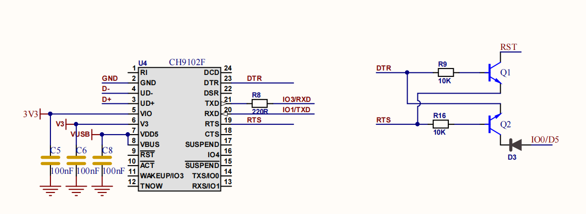
-
其中IO34~39是仅支持输入,不能用作输出。
-
FireBeetle 2 ESP32-E有2个8-bit DAC通道,将2路数字信号分别转化为2个模拟电压信号输出,两个通道可以独立地工作。DAC电路由内置电阻串和1个缓冲器组成。这2个DAC可以作为参考电压使用。
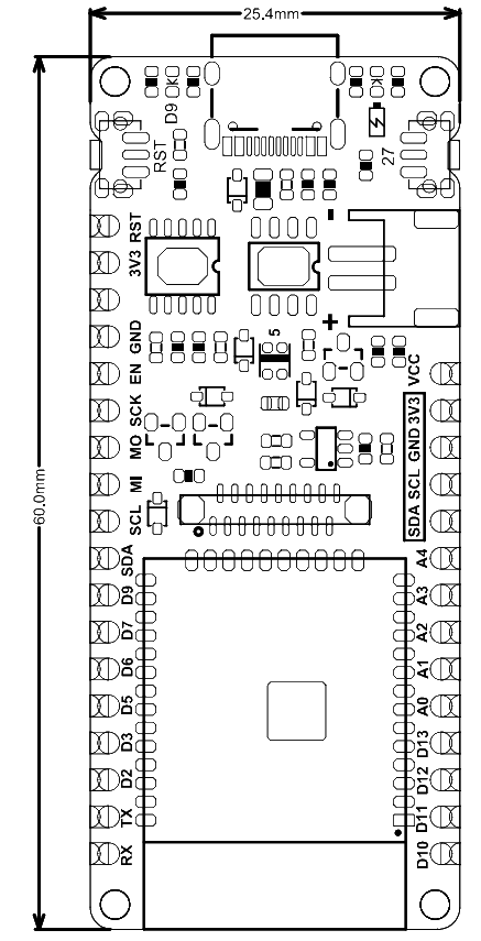
7.尺寸图
- pin脚间距:2.54mm
- 安装孔间距:22mm和56.6mm
- 安装孔尺寸:2mm
- 主板尺寸:25.4.00mm×60.00mm
- 板厚:1.6mm
8. 首次使用
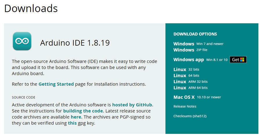
8.1 下载Arduino IDE
- 进入Arduino官网,下载Arduino IDE: 点击下载Arduino IDE
- 再根据自己的电脑系统,选择合适的IDE包
8.2 配置编译环境
当你首次使用FireBeetle 2 ESP32-E主控时,需要在Arduino IDE中安装ESP32主板,具体操作步骤如下:
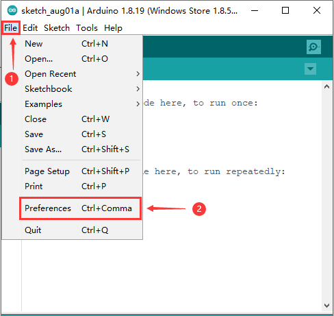
- 打开Arduino IDE,点击File->Preferences,如下图所示。
- 进入Preferences窗口,点击图中箭头所指图标。
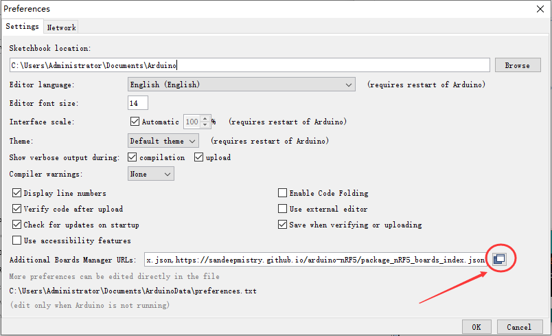
-
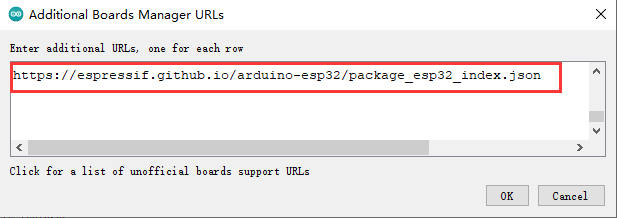
在弹出的窗口中,换行添加以下json链接:
https://espressif.github.io/arduino-esp32/package_esp32_index.json
再点击OK,如下图所示。
- 下载SDK,按以下操作步骤,进入“板卡管理”窗口。
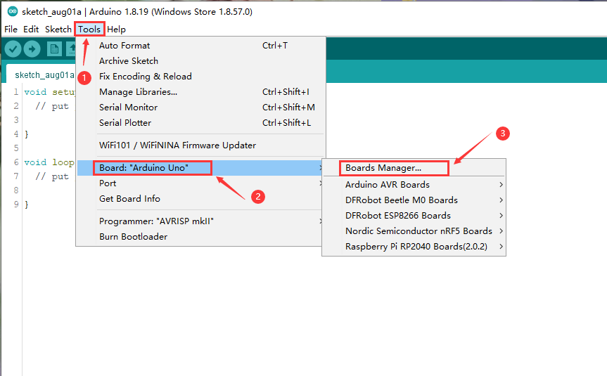
- 在窗口的搜索栏中输入“ESP32”,会自动出现“esp32”的SDK,点击Install 即可。
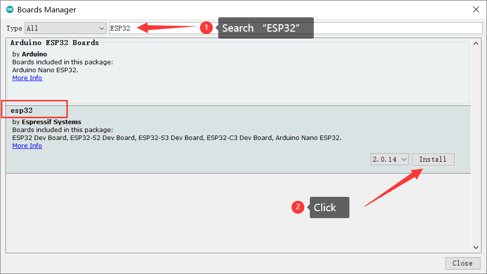
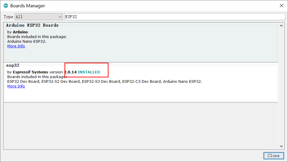
- 直到出现红框中的内容,SDK安装完毕,关闭窗口。
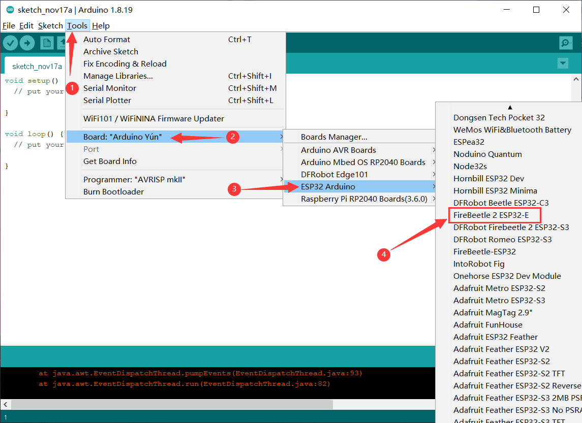
- 接着选择FireBeetle 2 ESP32-E开发板,点击Tools-->Board-->ESP32 Arduino-->FireBeetle ESP32-E,如下图所示。
- 开发板选择完毕,将你的FireBeetle 2 ESP32-E连接到电脑,这里COM4是连接主控之后才多出的端口,说明是FireBeetle 2 ESP32-E主板所在的端口是它,所以按以下步骤选择它。
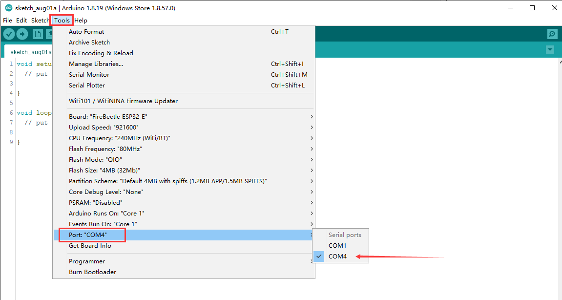
- 至此,FireBeetle 2 ESP32-E主板的Arduino IDE 编译环境配置完成,可以开始使用了。
9. Arduino 基础教程
9.1 Blink
在本节中,我们将从点亮LED灯开始来使用FireBeetle 2 ESP32-E主板。
硬件准备:
- FireBeetle 2 ESP32-E (SKU: DFR0654)×1
功能说明:
FireBeetle 2 ESP32-E主板将板载LED灯默认连接到2/D9引脚,LED灯的位置如图所示,现在我们将编程点亮它。
示例程序:
程序功能:让板载的LED灯按一秒的间隔闪烁。
int ledPin = D9;    //定义LED灯引脚
void setup(){
   pinMode(ledPin, OUTPUT);// 设置ledPin引脚为输出模式
}

void loop(){
   digitalWrite(ledPin, HIGH);   // 输出高电平,点亮LED灯
   delay(1000);     //延迟1秒
   digitalWrite(ledPin, LOW);  // 输出低电平,熄灭LED灯
   delay(1000);
}
程序执行结果:
当程序上传成功,板载的LED灯按1秒的间隔时间反复闪烁。
9.2 GPIO
9.2.1 数字引脚
9.2.1.1 写数字引脚
硬件准备:
- FireBeetle 2 ESP32-E (SKU: DFR0654)×1
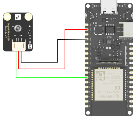
- Gravity: 数字蓝色LED发光模块(SKU: DFR0021-B)×1
硬件连接:
示例程序:
程序功能:数字引脚输出高电平,点亮LED灯。
int ledPin = D7; //  定义LED灯引脚
void setup(){
   pinMode(ledPin, OUTPUT);
   digitalWrite(ledPin, HIGH);
}

void loop(){
}
程序执行结果:
程序上传完成,可以看到蓝色LED灯亮起。
9.2.1.2 读数字引脚
硬件准备:
- FireBeetle 2 ESP32-E (SKU: DFR0654)×1
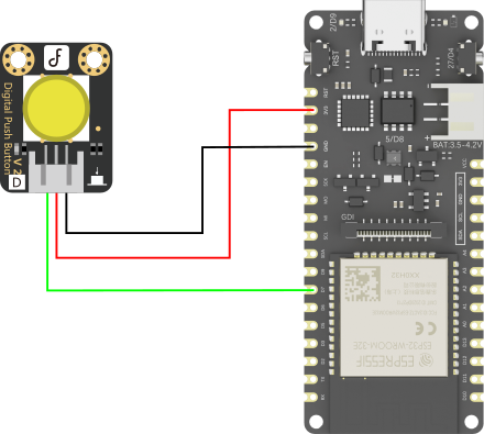
- Gravity: 数字大按钮模块 黄色(SKU: DFR0029-Y)×1
硬件连接:
示例程序:
程序功能:当按钮按下,板载的LED灯亮起,松开按钮,则LED灯熄灭
int buttonPin = D7;   //  定义按钮引脚
int ledPin = D9;     //定义LED灯引脚
int buttonState = 0;  //用于读取按钮状态的变量

void setup(){
   pinMode(buttonPin, INPUT);
   pinMode(ledPin, OUTPUT);
}

void loop(){
   buttonState = digitalRead(buttonPin); //读取按钮值的状态

   if(buttonState == HIGH){    //检查按钮是否按下
     digitalWrite(ledPin,HIGH);
   } else{
     digitalWrite(ledPin,LOW);
   }
}
程序执行结果:
程序上传成功后,按下连接在D7的按钮后,板载的LED灯亮起,松开按钮后LED灯熄灭。
9.2.2 模拟引脚
9.2.2.1 读模拟引脚
硬件准备:
- FireBeetle 2 ESP32-E (SKU: DFR0654)×1
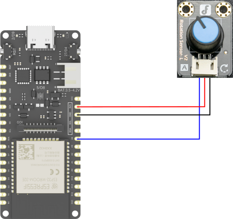
- Gravity: 模拟角度传感器Rotation Sensor(SKU: DFR0054)×1
功能说明:
ADC(模数转换器即 A/D 转换器),是指将模拟信号转变成数字信号。真实世界的模拟信号,例如温度、压力、声音或者图像等,需要转换成更容易储存、处理和发射的数字形式。FireBeetle 2 ESP32-E的ADC是12位的,最大输出值为 4095。
硬件连接:
示例程序:
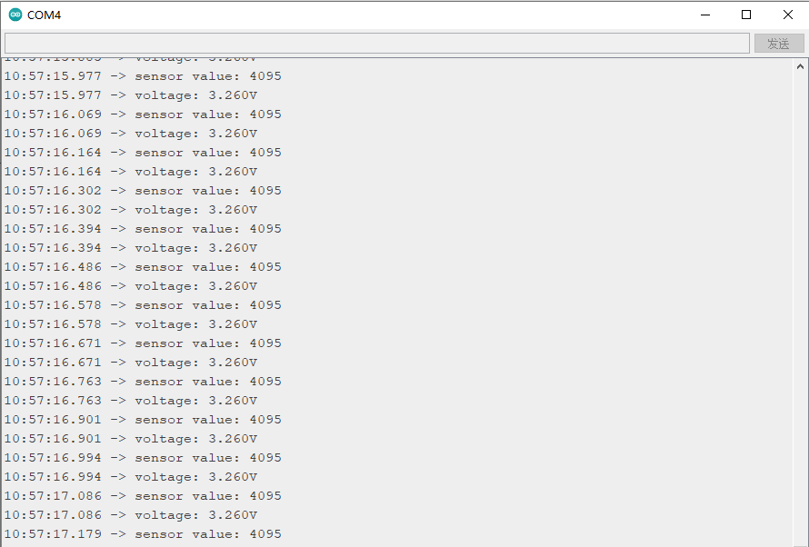
以下程序将读取接在IO15/A4引脚上的传感器模块,然后在串口监视器中实时打印模拟角度传感器的值和检测到的电压。
int sensorPin = A4;   //  定义模拟角度传感器引脚
int sensorValue = 0;

void setup(){
   pinMode(sensorPin, INPUT);
   Serial.begin(9600);   //初始化串口
}

void loop(){
   sensorValue = analogRead(sensorPin);    //读取在模拟引脚A4的传感器值
   Serial.printf("sensor value: %d\n", sensorValue);  //打印读取到的传感器数值
   Serial.printf("voltage: %.3fV\n", sensorValue * 3.26 / 4095);  //打印检测到的电压
   delay(100);
}
程序执行结果:
打开串口监视器,可以看到窗口打印出了当前角度传感器的值,转动角度传感器,打印的值也随之改变。可以看到,当传感器的值为4095时,检测到的电压值约为3.3V。
9.2.2.2 PWM输出(模拟写)
硬件准备:
- FireBeetle 2 ESP32-E (SKU: DFR0654)×1
功能说明:
PWM(Pulse Width Modulation)是利用MCU的数字接口,采用脉冲宽度调制的方式来对模拟电路进行控制的一种非常有效的技术,广泛应用在灯光控制、电机速度控制、测量、通信到功率控制与变换的许多领域中。
ESP32的PWM控制器具有16个独立通道,可配置为生成具有不同属性的PWM信号。所有可用作输出的引脚都可以用作PWM引脚(GPIO 34至39无法生成PWM)。
在Arduino开发环境中,PWM输出定义为模拟输出,使用Arduino 通过PWM调光LED灯必须遵循的步骤:
-
首先,选择一个PWM通道,从0到15共有16个通道。
-
然后,设置PWM信号频率。对于LED来说,使用5000 Hz的频率是合适的。
-
设置信号的占空比分辨率,分辨率从1到16位。此处将使用8位分辨率,可以使用0到255的值来控制LED亮度(2的8次方)
下方示例将演示使用PWM驱动板载LED灯呈现呼吸灯状态。该示例无需外部硬件连接。
示例程序:
程序功能:使用PWM驱动板载LED灯呈现呼吸灯状态。
const int ledPin = D9; //定义LED引脚
const int freq = 5000;   //设置PWM信号频率
const int ledChannel = 0;   //从0~15共有16个通道,设置PWM通道0
const int resolution = 8;    //设置信号的占空比分辨率,从1到16位。此处选择8位分辨率,范围为0~255

void setup(){
  ledcSetup(ledChannel,freq,resolution);
  ledcAttachPin(ledPin,ledChannel);    //设置输出PWM信号的引脚和产生PWM信号的通道

}

void loop(){
  for(int dutyCycle = 0;dutyCycle <= 255;dutyCycle++){
    ledcWrite(ledChannel,dutyCycle);
    delay(15);
  }
  for(int dutyCycle = 255;dutyCycle >= 0;dutyCycle--){
    ledcWrite(ledChannel,dutyCycle);
    delay(15);
  }
}
程序执行结果:
程序上传成功后,板载的绿色LED发光的强度呈现出逐渐变亮然后逐渐变弱的呼吸的状态。
9.3 RGB灯
Firebeetle 2 ESP32-E板载了一个WS2812RGB灯,IO5/D8引脚连接的,该引脚在板上并未引出,因此IO5/D8为RGB灯的专属引脚,位置如下图所示:
硬件准备:
- FireBeetle 2 ESP32-E (SKU: DFR0654)×1
功能说明:
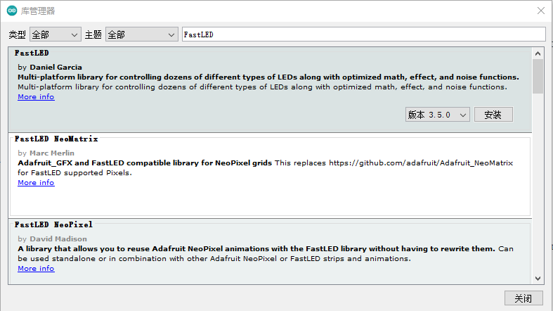
FastLED是一款功能强大却简单易用的可以控制WS2812、LPD8806等LED光带的Arduino第三方库。目前FastLED是公认的Arduino开发者应用最为广泛的LED控制库之一。和前面安装FireBeetle 2 ESP32-E的SDK方法一样,安装FastLED库,如下图所示,点击安装即可。
接下来我们来学习如何点亮RGB灯,无需外部硬件连接。
示例程序:
程序功能:点亮板载RGB灯,使其循环依次显示红色、绿色、蓝色和混色。
#include <FastLED.h>
#define NUM_LEDS 1     //RGB灯珠数量
#define DATA_PIN D8    //控制RGB灯引脚
#define LED_TYPE NEOPIXEL    //RGB灯带型号
CRGB leds[NUM_LEDS];    //实例化RGB灯

void setup() {
    FastLED.addLeds<LED_TYPE, DATA_PIN>(leds, NUM_LEDS);     //初始化RGB灯
}

void loop() {
  leds[0] = CRGB::Red;     //灯珠显示红色
  FastLED.show();
  delay(1000);
  leds[0] = CRGB::Green;    //灯珠显示绿色
  FastLED.show();
  delay(1000);
  leds[0] = CRGB::Blue;     // 灯珠显示蓝色
  FastLED.show();
  delay(1000);
  leds[0] = CRGB(random(0,255),random(0,255),random(0,255));    // 灯珠显示混色
  FastLED.show();
  delay(1000);
}
程序执行结果:
程序上传成功后,板载的RGB灯每隔一秒切换红绿蓝三色和混色。
9.4 串口
硬件准备:
- FireBeetle 2 ESP32-E (SKU: DFR0654)×1
功能说明:
前面已经学习了如何操作IO口点亮LED灯,这里学习串口通信的原理。FireBeetle 2 ESP32-E总共有2个硬串口,并且这2个串口管脚都是可以重映射的,USB所使用的是Serial,即UART0。
| 串口名 | Arduino | TX | RX |
|---|---|---|---|
| UART0 | Serial | pin1 | pin3 |
| UART2 | Serial2 | pin17 | pin16 |
示例程序:
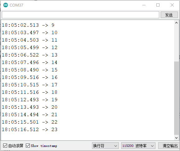
程序功能:使用 UART 串口,每秒打印一次计时数据。
void setup() {
  Serial.begin(115200);    //初始化串口,设置波特率为115200
}

void loop() {
 static unsigned long i = 0;  //静态变量(局部变量),只初始化一次
 Serial.println(i++);   //串口打印i++
 delay(1000);
}
程序执行结果:
打开串口监视器,将波特率设置为115200,可以看到打印值每隔一秒增加。
9.5 电容触摸传感器
本节中介绍了如何通过 Arduino 代码获取FireBeetle 2 ESP32-E的触摸传感器状态,并打印状态。
硬件准备:
- FireBeetle 2 ESP32-E (SKU: DFR0654)×1
功能说明:
FireBeetle 2 ESP32-E提供了电容触摸传感器的功能,共有T0~T6共7个touch传感器可用。对应引脚序号如下表所示:
| 触摸传感器序号 | ESP32-E对应的引脚号 |
|---|---|
| T0 | IO4/D12 |
| T1 | IO0/D5 |
| T2 | IO2/D9(连接板载LED灯,不能用该引脚测试触摸功能) |
| T3 | IO15/A4 |
| T4 | IO13/D7 |
| T5 | IO12/D13 |
| T6 | IO14/D6 |
无需设置PinMode,touchRead()返回值为0~255。触摸强度越大,返回值越小。 获取触摸传感器的 GPIO 状态,只需要调用 touchRead 函数,函数原型如下: uint16_t touchRead(uint8_t pin) 。
示例程序:
程序功能:烧录此例程,将使用IO4/D12引脚作为触摸按键,并通过串口监视器返回触摸值。
void setup() {
  Serial.begin(115200);
  Serial.println("FireBeetle Board-ESP32 Touch Test");
}

void loop() {
  Serial.println(touchRead(T0));
  delay(100);
}
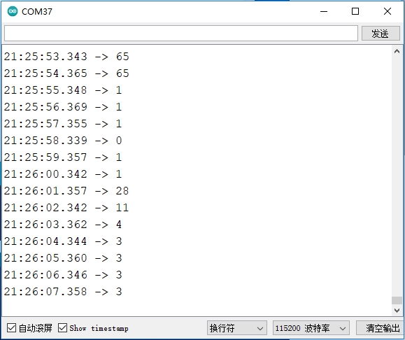
程序执行结果:
当手指触摸IO4/D12引脚时,触摸强度越大,返回值越小。没触摸时的值为65。
9.6 中断
功能说明:
FireBeetle 2 ESP32-E开发板引出的所有GPIO,除了被占用的、有特定功能的IO口,都可以作为外部中断引脚。
- 开启外部中断(attachInterrupt(pin,function,mode)),参数如下:
pin: 外部中断引脚
function : 外部中断回调函数
mode : 5种外部中断模式,见下表:
| 中断触发模式 | 说明 |
|---|---|
| RISING | 上升沿触发 |
| FALLING | 下降沿触发 |
| CHANGE | 电平变化触发 |
| ONLOW | 低电平触发 |
| ONHIGH | 高电平触发 |
- 关闭引脚中断 detchInterrupt((pin),无返回值。
硬件准备:
- FireBeetle 2 ESP32-E (SKU: DFR0654)×1
示例程序:
程序功能:按钮按下,触发中断,串口打印按钮按下次数。
#include <Arduino.h>

struct Button {         //定义按钮结构体
    const uint8_t PIN;      //定义按钮引脚
    uint32_t numberKeyPresses;   //定义按钮按下的次数
    bool pressed;        //判断按钮是否被按下,按下为true
};
Button button = {27, 0, false};  //实例化了一个按钮,使用板载按钮

void ARDUINO_ISR_ATTR isr() {    //中断处理函数

    button.pressed = true;
}

void setup() {
    Serial.begin(115200);
    pinMode(button.PIN, INPUT_PULLUP);
    attachInterrupt(button.PIN, isr, FALLING);    //注册中断函数,设置触发方式为下降沿触发
}

void loop() {
    if (button.pressed) {
      button.pressed = false;
      delay(50);
      if(digitalRead(button.PIN)==LOW){
         button.numberKeyPresses += 1;
         Serial.printf("Button  has been pressed %u times\n", button.numberKeyPresses); //按钮按下,打印按钮按下累计次数
      }

    }
}
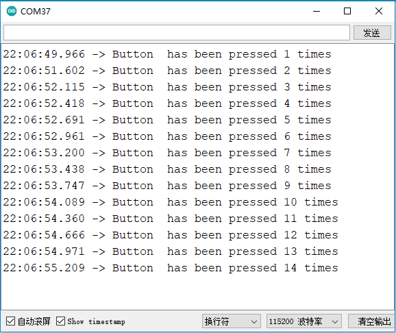
程序执行结果
当程序上传成功后,按下板载的用户按钮一次,则串口打印一次信息,再按下按钮,则打印累加信息,如下图所示。
9.7 I2C通信
功能说明:
FireBeetle 2 ESP32-E的I2C可以配置到任意 I/O 口,可以通过传递相关参数进行配置。为了方便使用,我们已经将 I2C 进行了默认配置,在使用上完全兼容 Arduino,默认配置引脚可以在前面引脚排列图中看到。
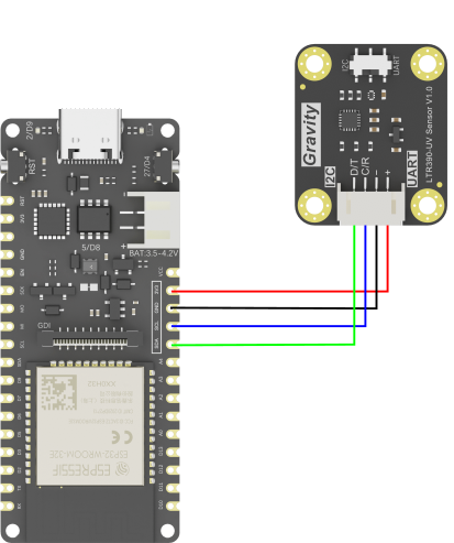
本节将基于I2C默认配置,驱动LTR390-UV紫外线传感器获取环境光强度。关于如何使用LTR390-UV紫外线传感器,请点击LTR390-UV紫外线传感器使用教程。
硬件准备:
-
FireBeetle 2 ESP32-E (SKU: DFR0654)×1
-
LTR390 UV Module(SKU: SEN0540)×1
硬件连接:
示例程序:
程序功能:读取当前环境下的光照强度。
#include "DFRobot_LTR390UV.h"
DFRobot_LTR390UV ltr390(/*addr = */LTR390UV_DEVICE_ADDR, /*pWire = */&Wire);

void setup()
{
  Serial.begin(115200);
  while(ltr390.begin() != 0){
    Serial.println(" Sensor initialize failed!!");
    delay(1000);
  }
  Serial.println(" Sensor  initialize success!!");
  ltr390.setALSOrUVSMeasRate(ltr390.e18bit,ltr390.e100ms);//18位数据,采样时间100ms
  ltr390.setALSOrUVSGain(ltr390.eGain3);//3倍增益
  ltr390.setMode(ltr390.eALSMode);//设置环境光模式
}
void loop()
{
  float als = 0;
  als = ltr390.readALSTransformData();//获取环境光转换后数据,只能在环境光模式下使用
  Serial.print("ALS:");
  Serial.print(als);
  Serial.println("Lux");
  delay(1000);
}
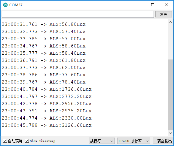
程序执行结果:
当程序上传完成,打开串口监视器,可以看到紫外线传感器在不断地获取当前的光照强度值。
9.8 SPI通信
功能说明:
在很多传感器中都使用SPI通信,因为SPI通信速率相对于I2C更快,没有地址冲突的弊端。SPI是 一种高速的、全双工、同步的通信总线,而FireBeetle 2 ESP32-E的SPI可以配置到所有I/O,您可以阅览底层代码进行使用(初学者不建议使用)。为了更好的使用体验,FireBeetle 2 ESP32-E默认情况下配置了IO18(SCK)、IO19(MISO)、IO23(MOSI)为SPI口,在使用上完全兼容Arduino。
硬件准备:
- FireBeetle 2 ESP32-E (SKU: DFR0654)×1
- Gravity: I2C OLED-2864 显示屏(SKU: DFR0486)×1
软件准备:
- 下载GDL库:https://gitee.com/dfrobot/DFRobot_GDL
硬件连接:
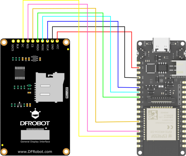
管脚连接说明:
- FireBeetle 2 ESP32-E: 3V3 引脚---(连接)---显示屏:VCC 引脚
- FireBeetle 2 ESP32-E: GND 引脚---(连接)---显示屏:GND 引脚
- FireBeetle 2 ESP32-E: SCK 引脚---(连接)---显示屏:SCLK 引脚
- FireBeetle 2 ESP32-E: MO 引脚---(连接)---显示屏:MOSI 引脚
- FireBeetle 2 ESP32-E: MI 引脚---(连接)---显示屏:MISO 引脚
- FireBeetle 2 ESP32-E: D6 引脚---(连接)---显示屏:CS 引脚
- FireBeetle 2 ESP32-E: D3 引脚---(连接)---显示屏:RES 引脚
- FireBeetle 2 ESP32-E: D2 引脚---(连接)---显示屏:DC 引脚
示例程序:
程序功能:通过SPI通信方式驱动显示屏,显示文字和数字。
#include "DFRobot_GDL.h"
#define TFT_DC  D2
#define TFT_CS  D6
#define TFT_RST D3
#define TFT_BL  D13

DFRobot_ST7789_240x320_HW_SPI screen(/*dc=*/TFT_DC,/*cs=*/TFT_CS,/*rst=*/TFT_RST);

void setup() {
  Serial.begin(115200);    //初始化
  screen.begin();
  screen.setTextSize(2);   //文字大小为4,范围为1~4
  screen.fillScreen(COLOR_RGB565_BLACK);    //屏幕背景颜色
  screen.setFont(&FreeMono12pt7b);       //字体格式
  screen.setCursor(/*x=*/10,/*y=*/120);    // 文字起点
  screen.setTextColor(COLOR_RGB565_LGRAY);   //文字颜色
  screen.print("DFRobot");    //输出文字内容
  screen.setCursor(10,200);
  screen.setTextColor(COLOR_RGB565_GREEN);
  screen.setTextWrap(true);
  screen.print("20220828");
}

void loop() {
}
程序执行结果:
屏幕上显示白色的文字"DFRobot"和绿色的"20220828"的数字。
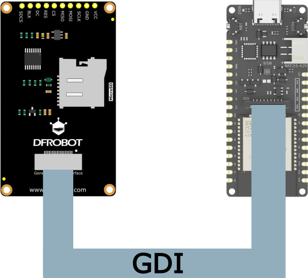
9.9 GDI接口
功能说明:
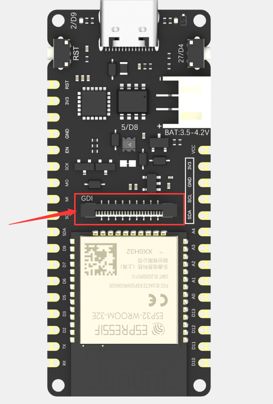
此接口为DFRbot专用GDI显示屏接口,使用18pin-FPC线连接,单线材连接屏幕,提供最简捷的屏幕使用方式。
以下是GDI接口使用的引脚列表:
| FPC PINS | FireBeetle ESP32 PINS | Description |
|---|---|---|
| VCC | 3V3 | 3.3V |
| BLK(PWM调光) | 12/D13 | 背光 |
| GND | GND | GND |
| SCLK | 18/SCK | SPI时钟 |
| MOSI | 23/MOSI | 主机输出,从机输入 |
| MISO | 19/MISO | 主机输入,从机输出 |
| DC | 25/D2 | 数据/命令 |
| RES | 26/D3 | 复位 |
| CS | 14/D6 | TFT片选 |
| SDCS | 13/D7 | SD卡片选 |
| FCS | 0/D5 | 字库 |
| TCS | 4/D12 | 触摸 |
| SCL | 22/SCL | I2C时钟 |
| SDA | 21/SDA | I2C数据 |
| INT | 16/D11 | INT |
| BUSY-TE | 17/D10 | 防撕裂引脚 |
| X1 | NC | 自定义引脚1 |
| X2 | NC | 自定义引脚2 |
使用FPC连接屏幕时根据GDL demo配置所需对应的引脚号即可,通常只需要根据不同主控配置三个引脚,该屏幕引脚配置如下。
/*ESP32 and ESP8266*/
#elif defined(ESP32) || defined(ESP8266)
#define TFT_DC  D2
#define TFT_CS  D6
#define TFT_RST D3
#define TFT_BL  D13
具体使用方式请参考,GDL显示屏wiki:https://wiki.dfrobot.com.cn/_SKU_DFR0664_2.0_240x320_LCD
支持GDI的显示屏:
- 1.54" 240x240 IPS广视角TFT显示屏
- 2.0" 320x240 IPS广视角TFT显示屏
- 2.8" 320x240 IPS TFT电阻触摸显示屏
- 3.5" 480x320 IPS TFT电容触摸显示屏
硬件准备:
- FireBeetle 2 ESP32-E (SKU: DFR0654)×1
- Gravity: I2C OLED-2864 显示屏(SKU: DFR0486)×1
硬件连接:
示例程序
程序功能:让显示屏显示"DFRobot"和"20220828"。
#include "DFRobot_GDL.h"
#define TFT_DC  D2
#define TFT_CS  D6
#define TFT_RST D3
#define TFT_BL  D13

DFRobot_ST7789_240x320_HW_SPI screen(/*dc=*/TFT_DC,/*cs=*/TFT_CS,/*rst=*/TFT_RST);

void setup() {
  Serial.begin(115200);    //初始化
  screen.begin();
  screen.setTextSize(2);   //文字大小为4,范围为1~4
  screen.fillScreen(COLOR_RGB565_BLACK);    //屏幕背景颜色
  screen.setFont(&FreeMono12pt7b);       //字体格式
  screen.setCursor(/*x=*/10,/*y=*/120);    // 文字起点
  screen.setTextColor(COLOR_RGB565_LGRAY);   //文字颜色
  screen.print("DFRobot");    //输出文字内容
  screen.setCursor(10,200);
  screen.setTextColor(COLOR_RGB565_GREEN);
  screen.setTextWrap(true);
  screen.print("20220828");
}

void loop() {
}
程序执行结果
连接好FPC线和上传完程序之后,显示屏显示英文和数字。
10. Arduino 进阶教程
10.1 Deep_sleep模式
功能说明:
本节介绍了如何通过 Arduino 代码让FireBeetle 2 ESP32-E 进入低功耗Deep_sleep模式。
ESP32 deep_sleep模式唤醒方式如下:
- 定时器唤醒
- 两种引脚唤醒方式
- 触摸按键唤醒
- ULP唤醒
返回:被唤醒原因码
| 原因码 | 对应原因 | 说明 |
|---|---|---|
| 2 | ESP_SLEEP_WAKEUP_EXT0 | 被RTC_GPIO唤醒 |
| 3 | ESP_SLEEP_WAKEUP_EXT1 | 被RTC_CNTL引脚集合的变化唤醒 |
| 4 | ESP_SLEEP_WAKEUP_TIMER | 被ESP的定时器唤醒 |
| 5 | ESP_SLEEP_WAKEUP_TOUCHPAD | 被触摸唤醒 |
| 6 | ESP_SLEEP_WAKEUP_ULP | 被ULP唤醒 |
硬件准备:
- FireBeetle 2 ESP32-E (SKU: DFR0654)×1
示例程序:
程序功能:设置FireBeetle 2 ESP32-E进入深度睡眠模式,唤醒源为定时器,每隔5秒唤醒一次。
#define uS_TO_S_FACTOR 1000000ULL   //微秒到秒的转换因子
#define TIME_TO_SLEEP  5        //ESP32-E进入深度睡眠的时间
RTC_DATA_ATTR int bootCount = 0;

void print_wakeup_reason(){
  esp_sleep_wakeup_cause_t wakeup_reason;
  wakeup_reason = esp_sleep_get_wakeup_cause();

  switch(wakeup_reason)             //判断唤醒原因
  {
    case ESP_SLEEP_WAKEUP_EXT0 : Serial.println("Wakeup caused by external signal using RTC_IO"); break;
    case ESP_SLEEP_WAKEUP_EXT1 : Serial.println("Wakeup caused by external signal using RTC_CNTL"); break;
    case ESP_SLEEP_WAKEUP_TIMER : Serial.println("Wakeup caused by timer"); break;
    case ESP_SLEEP_WAKEUP_TOUCHPAD : Serial.println("Wakeup caused by touchpad"); break;
    case ESP_SLEEP_WAKEUP_ULP : Serial.println("Wakeup caused by ULP program"); break;
    default : Serial.printf("Wakeup was not caused by deep sleep: %d\n",wakeup_reason); break;
  }
}

void setup(){
  Serial.begin(115200);
  delay(1000);
  ++bootCount;
  Serial.println("Boot number: " + String(bootCount));
  print_wakeup_reason();    //打印唤醒原因
  esp_sleep_enable_timer_wakeup(TIME_TO_SLEEP * uS_TO_S_FACTOR);
  Serial.println("Setup ESP32 to sleep for every " + String(TIME_TO_SLEEP) + " Seconds");
  Serial.println("Going to sleep now");  //现在我们已经设置了唤醒原因,如果需要设置外围设备处于深度睡眠状态,我们现在可以开始沉睡。如果没有提供唤醒源,但深度睡眠已启动,它将永远睡眠,除非硬件发生复位。
  Serial.flush();
  esp_deep_sleep_start();
  Serial.println("This will never be printed");
}

void loop(){
}
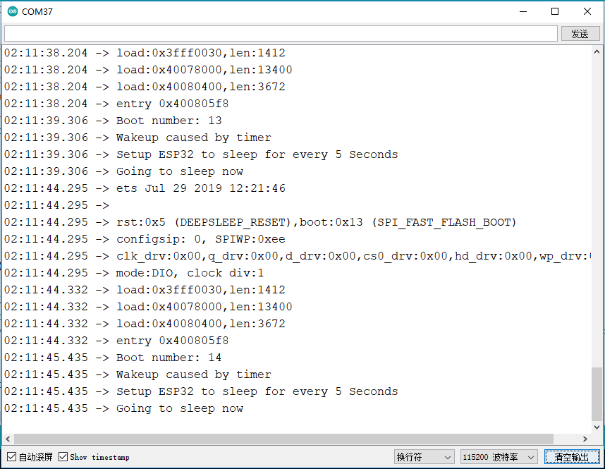
程序执行结果:
10.2 SD库的使用
10.2.1 SDClass类
功能说明
SDClass类提供了访问SD卡、操纵文件及文件夹的功能。其成员函数如下:
-
begin()
说明:初始化SD卡库和 SD卡。
语法:SD.begin()和begin(cspin)
当使用SD.begin()时,默认将Arduino SPI的SS引脚连接到SD卡的CS使能选择端;也可以使用begin(cspin)指定一个引脚连接到SD卡的CS使能选择端,但仍需保证 SPI 的SS引脚为输出模式,否则SD卡库将无法运行。
参数:
- cspin,连接到SD 卡CS端的Arduino引脚。
- 返回值:boolean型值,为 true表示初始化成功,为false表示初始化失败。
-
exists()
说明:检查文件或文件夹是否存在于SD卡中。语法:SD. exists(filename)
参数:- filename,需要检测的文件名。其中可以包含路径,路径用“/“分隔。
- 返回值:boolean型值,为 true表示文件或文件夹存在,为false表示文件或文件夹不存在。
-
open()
说明:打开SD卡上的一个文件。如果文件不存在,且以写入方式打开,则Arduino会创建一个指定文件名的文件。(所在路径必须事先存在)
语法:SD.open(filename)和SD.open(filename,mode)
参数:-
filename,需要打开的文件名。其中可以包含路径,路径用“/”分隔。
-
mode(可选),打开文件的方式,默认使用只读方式打开,也可以使用以下两种方式打开文件:
FILE_READ:只读方式打开文件;FILE_WRITE:写入方式打开文件。
-
返回值:返回被打开文件对应的对象;如果文件不能打开,则返回false。
-
-
remove()
说明:从SD卡移除一个文件。如果文件不存在,则函数返回值是不确定的,因此在移除文件之前,最好使用SD. exists(filename)先检测文件是否存在。
语法:SD. remove(filename)
参数:- filename,需要移除的文件名。其中可以包含路径,路径用“/”分隔。
- 返回值:boolean型值,为true表示文件移除成功,为false表示文件移除失败。
-
mkdir(filename)
说明:创建文件夹。
参数:- filename,需要创建的文件夹名。其中可以包含路径,路径用“/”分隔。
- 返回值: boolean型值,为 true表示创建成功,为false表示创建失败。
-
rmdir(filename)
说明:移除文件夹。被移除的文件夹必须是空的。 -
语法:SD.rmdir(filename)
-
参数:
- filename,需要移除的文件夹名。其中可以包含路径,路径用“/”分隔。
- 返回值:boolean型值,为 true表示移除成功,为false表示移除失败。
10.2.2 File类
File类提供了读/写文件的功能,该类的功能与之前使用的串口相关函数的功能非常类似。其成员函数如下:
-
available()
说明:检查当前文件中可读数据的字节数。语法:file. available()
参数:- file,一个File类型的对象。
- 返回值:可用字节数。
-
close()
说明:关闭文件,并确保数据已经被完全写入SD卡中。语法:file. close()
参数:- file,一个File类型的对象。
- 返回值:无。
-
flush()
说明:确保数据已经写入SD卡。当文件被关闭时,flush()会自动运行。语法:file.flush()
参数:- file,一个File类型的对象。
- 返回值:无。
-
peek()
说明:读取当前所在字节,但并不移动到下一个字节。
参数:- file,一个File类型的对象。
- 返回值:下一个字节或者下一个字符。如果没有可读数据,则返回-1。
-
position( )
说明:获取当前在文件中的位置(即下一个被读/写的字节的位置)。语法:file. position()
参数:- file,一个File类型的对象。
- 返回值:在当前文件中的位置。
-
print()
说明:输出数据到文件。要写入的文件应该已经被打开,且等待写入。语法:file. print(data)或者file. print(data,BASE)
参数:-
file,一个File类型的对象。
-
data,要写入的数据(可以是类型char、byte 、int 、long 或 String)。
-
BASE(可选),指定数据的输出形式:BIN(二进制);OCT(八进制);DEC(十进制);HEX(十六进制)。
-
返回值:发送的字节数。
-
-
println()
说明:输出数据到文件,并回车换行。语法:file. println(data)或者file.println(data,BASE)
参数:- file,一个File类型的对象。
- data,要写入的数据(类型可以是char、byte、int、long或String)。
- BASE(可选),指定数据的输出形式:BIN(二进制);OCT(八进制);DEC(十进制);HEX(十六进制)。
- 返回值:发送的字节数。
-
seek()
说明:跳转到指定位置。该位置必须在0到该文件大小之间。语法:file. seek( pos)
参数:- file,一个File类型的对象。
- pos,需要查找的位置。
- 返回值:boolean型值,为 true表示跳转成功,为false表示跳转失败。
-
size()
说明:获取文件的大小。语法:filue. size()
参数:- file,一个File类型的对象。
- 返回值:以字节为单位的文件大小。
-
read()
说明:读取1B数据。语法:file.read()
参数:
- file,一个File类型的对象。
- 返回值:下一个字节或者字符;如果没有可读数据,则返回-1。
-
write()
说明:写入数据到文件。语法:file. write(data) 和file. write(buf,len)
参数:- file,一个File类型的对象。
- data:要写入的数据,类型可以是 byte、char或字符串(char * )。
- buf,一个字符数组或者字节数据。
- len,buf数组的元素个数。
- 返回值:发送的字节数。
-
isDirectory()
说明:判断当前文件是否为目录。语法:file.isDirectory()
参数:- file,一个File类型的对象。
- 返回值:boolcan型值,为 true表示是目录,为 false表示不是目录。
-
openNextFile()
说明:打开下一个文件。语法:file.openNextFile()
参数:- file,一个File类型的对象。
- 返回值:下一个文件对应的对象。
-
rewindDirectory()
说明:回到当前目录中的第一个文件。语法:file.rewindDirectory()
参数:- file,一个File类型的对象。
- 返回值:无。
10.2.3 硬件准备
- FireBeetle 2 ESP32-E (SKU: DFR0654)×1
- MicroSD卡 读卡器模块(SKU: DFR0229)×1
10.2.4 硬件连接
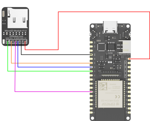
管脚连接说明:
- FireBeetle 2 ESP32-E: VCC 引脚---(连接)---读卡器:+5V 引脚
- FireBeetle 2 ESP32-E: GND 引脚---(连接)---读卡器:GND 引脚
- FireBeetle 2 ESP32-E: SCK 引脚---(连接)---读卡器:SCK 引脚
- FireBeetle 2 ESP32-E: MO 引脚---(连接)---读卡器:MOSI 引脚
- FireBeetle 2 ESP32-E: MI 引脚---(连接)---读卡器:MISO 引脚
- FireBeetle 2 ESP32-E: D6 引脚---(连接)---读卡器:SS 引脚
10.2.5 示例程序
程序功能:以下程序实现了访问SD卡、操纵文件及文件夹等功能,包括读写文件。
/* Connect the SD card to the following pins:
 * SD Card | ESP32
 *    MISO    MISO
 *    SCK     SCK
 *    ss      D6
 *    MOSI    MOSI
 *    GND     GND
 *    +5V     VCC
 */
#include "FS.h"
#include "SD.h"
#include "SPI.h"

void listDir(fs::FS &fs, const char * dirname, uint8_t levels){
    Serial.printf("Listing directory: %s\n", dirname);

    File root = fs.open(dirname);
    if(!root){
        Serial.println("Failed to open directory");
        return;
    }
    if(!root.isDirectory()){
        Serial.println("Not a directory");
        return;
    }

    File file = root.openNextFile();
    while(file){
        if(file.isDirectory()){
            Serial.print("  DIR : ");
            Serial.println(file.name());
            if(levels){
                listDir(fs, file.path(), levels -1);
            }
        } else {
            Serial.print("  FILE: ");
            Serial.print(file.name());
            Serial.print("  SIZE: ");
            Serial.println(file.size());
        }
        file = root.openNextFile();
    }
}

void createDir(fs::FS &fs, const char * path){
    Serial.printf("Creating Dir: %s\n", path);
    if(fs.mkdir(path)){
        Serial.println("Dir created");
    } else {
        Serial.println("mkdir failed");
    }
}

void removeDir(fs::FS &fs, const char * path){
    Serial.printf("Removing Dir: %s\n", path);
    if(fs.rmdir(path)){
        Serial.println("Dir removed");
    } else {
        Serial.println("rmdir failed");
    }
}

void readFile(fs::FS &fs, const char * path){
    Serial.printf("Reading file: %s\n", path);

    File file = fs.open(path);
    if(!file){
        Serial.println("Failed to open file for reading");
        return;
    }

    Serial.print("Read from file: ");
    while(file.available()){
        Serial.write(file.read());
    }
    file.close();
}

void writeFile(fs::FS &fs, const char * path, const char * message){
    Serial.printf("Writing file: %s\n", path);

    File file = fs.open(path, FILE_WRITE);
    if(!file){
        Serial.println("Failed to open file for writing");
        return;
    }
    if(file.print(message)){
        Serial.println("File written");
    } else {
        Serial.println("Write failed");
    }
    file.close();
}

void appendFile(fs::FS &fs, const char * path, const char * message){
    Serial.printf("Appending to file: %s\n", path);

    File file = fs.open(path, FILE_APPEND);
    if(!file){
        Serial.println("Failed to open file for appending");
        return;
    }
    if(file.print(message)){
        Serial.println("Message appended");
    } else {
        Serial.println("Append failed");
    }
    file.close();
}

void renameFile(fs::FS &fs, const char * path1, const char * path2){
    Serial.printf("Renaming file %s to %s\n", path1, path2);
    if (fs.rename(path1, path2)) {
        Serial.println("File renamed");
    } else {
        Serial.println("Rename failed");
    }
}

void deleteFile(fs::FS &fs, const char * path){
    Serial.printf("Deleting file: %s\n", path);
    if(fs.remove(path)){
        Serial.println("File deleted");
    } else {
        Serial.println("Delete failed");
    }
}

void testFileIO(fs::FS &fs, const char * path){
    File file = fs.open(path);
    static uint8_t buf[512];
    size_t len = 0;
    uint32_t start = millis();
    uint32_t end = start;
    if(file){
        len = file.size();
        size_t flen = len;
        start = millis();
        while(len){
            size_t toRead = len;
            if(toRead > 512){
                toRead = 512;
            }
            file.read(buf, toRead);
            len -= toRead;
        }
        end = millis() - start;
        Serial.printf("%u bytes read for %u ms\n", flen, end);
        file.close();
    } else {
        Serial.println("Failed to open file for reading");
    }


    file = fs.open(path, FILE_WRITE);
    if(!file){
        Serial.println("Failed to open file for writing");
        return;
    }

    size_t i;
    start = millis();
    for(i=0; i<2048; i++){
        file.write(buf, 512);
    }
    end = millis() - start;
    Serial.printf("%u bytes written for %u ms\n", 2048 * 512, end);
    file.close();
}

void setup(){
    Serial.begin(115200);
    if(!SD.begin()){
        Serial.println("Card Mount Failed");
        return;
    }
    uint8_t cardType = SD.cardType();

    if(cardType == CARD_NONE){
        Serial.println("No SD card attached");
        return;
    }

    Serial.print("SD Card Type: ");
    if(cardType == CARD_MMC){
        Serial.println("MMC");
    } else if(cardType == CARD_SD){
        Serial.println("SDSC");
    } else if(cardType == CARD_SDHC){
        Serial.println("SDHC");
    } else {
        Serial.println("UNKNOWN");
    }

    uint64_t cardSize = SD.cardSize() / (1024 * 1024);
    Serial.printf("SD Card Size: %lluMB\n", cardSize);

    listDir(SD, "/", 0);
    createDir(SD, "/mydir");
    listDir(SD, "/", 0);
    removeDir(SD, "/mydir");
    listDir(SD, "/", 2);
    writeFile(SD, "/hello.txt", "Hello ");
    appendFile(SD, "/hello.txt", "World!\n");
    readFile(SD, "/hello.txt");
    deleteFile(SD, "/foo.txt");
    renameFile(SD, "/hello.txt", "/foo.txt");
    readFile(SD, "/foo.txt");
    testFileIO(SD, "/test.txt");
    Serial.printf("Total space: %lluMB\n", SD.totalBytes() / (1024 * 1024));
    Serial.printf("Used space: %lluMB\n", SD.usedBytes() / (1024 * 1024));
}

void loop(){

}
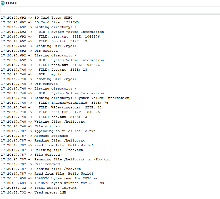
10.2.6 程序执行结果:
当程序上传成功,打开串口监视器,可以看到对SD的一系列操作,以及读取它的内存。
10.3 WIFI
10.3.1 WIFI基础示例
功能说明
ESP32具有WIFI功能,以下示例使用ESP32创建了一个wifi服务器,使用客户端连接到该服务器,远程遥控LED的亮灭。
硬件准备:
- FireBeetle 2 ESP32-E (SKU: DFR0654)×1
- 手机 ×1
示例程序
程序功能:手机连接FireBeetle 2 ESP32-E创建的wifi服务器,访问192.168.4.1,遥控板载LED的亮灭。
/*WiFiAccessPoint.ino 创建了一个wifi热点并提供了一个web服务
  Steps:
  1. 连接到这个wifi "yourAp"
  2. 访问 https://192.168.4.1/H 来开灯或者访问https://192.168.4.1/L 来关灯*/

#include <WiFi.h>
#include <WiFiClient.h>
#include <WiFiAP.h>

// 设置你的wifi与密码
const char *ssid = "esp32";
const char *password = "123456789";

WiFiServer server(80);

void setup() {
  pinMode(LED_BUILTIN, OUTPUT); //将LED引脚设置为输出模式
  Serial.begin(115200);
  Serial.println();
  Serial.println("Configuring access point...");

  // 配置wifi以及获取IP地址.
  WiFi.softAP(ssid, password);
  IPAddress myIP = WiFi.softAPIP();
  Serial.print("AP IP address: ");
  Serial.println(myIP);
  server.begin();
  Serial.println("Server started");
}

void loop() {
  WiFiClient client = server.available();   // 监听服务器

  if (client) {                             // 如果服务器来消息
    Serial.println("New Client.");           // 从串口打印消息
    String currentLine = "";                // 生成一个String来保存来自客户端的传入数据
    while (client.connected()) {
        char c = client.read();
        Serial.write(c);
        if (c == '\n') {
          if (currentLine.length() == 0) {
            client.println("HTTP/1.1 200 OK");
            client.println("Content-type:text/html");
            client.println();
            client.print("Click <a href=\"/H\">here</a> to turn ON the LED.<br>");
            client.print("Click <a href=\"/L\">here</a> to turn OFF the LED.<br>");
            client.println();
            break;
          } else {
            currentLine = "";
          }
        } else if (c != '\r') {
          currentLine += c;
        }
        if (currentLine.endsWith("GET /H")) {
          digitalWrite(LED_BUILTIN, HIGH);               // GET /H 开灯
        }
        if (currentLine.endsWith("GET /L")) {
          digitalWrite(LED_BUILTIN, LOW);                // GET /L 关灯
      }
    }
    client.stop();
    Serial.println("Client Disconnected.");
  }
}
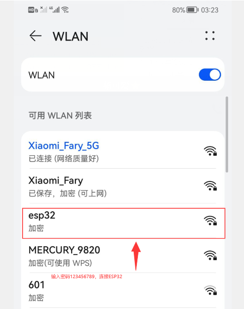
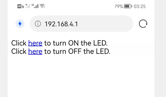
程序执行结果
连接上ESP32后,访问所给网址,点击开灯,则板载的LED灯亮起;点击关灯,则板载的LED灯熄灭。
- 连接esp32
- 访问结果
10.3.2 WIFI获取网络时间
功能说明
ESP32同时支持STA以及AP模式的WiFi连接。
- STA 模式:ESP32模块通过路由器连接互联网,手机或电脑通过互联网实现对设备的远程控制。
- AP 模式:ESP32模块作为热点,实现手机或电脑直接与模块通信,实现局域网无线控制。
- STA+AP 模式:两种模式的共存模式,即可以通过互联网控制可实现无缝切换,方便操作。
以下例程中默认为STA模式。
硬件准备:
- FireBeetle 2 ESP32-E (SKU: DFR0654)×1
示例程序:
程序功能:从网络时间服务器上获取并设置时间。
#include <WiFi.h>
const char* ssid="WIFI_SSID"; //填写WIFI名称
const char* password="WIFI_PASSWORD"; //填写WIFI密码
const char* ntpServer = "pool.ntp.org"; //获取网络时间服务器的时间
const long gmtOffset_sec = 28800; //这里采用UTC计时,中国为东八区,就是 8*60*60
const int daylightOffset_sec = 0; //使用夏令时 daylightOffset_sec = 3600,否则就等于0
void printLocalTime(){
struct tm timeinfo;
if(!getLocalTime(&timeinfo)){ //如果获取到了本地时间,放入timeinfo结构体中
Serial.println("Failed to obtian time");
return ;
}
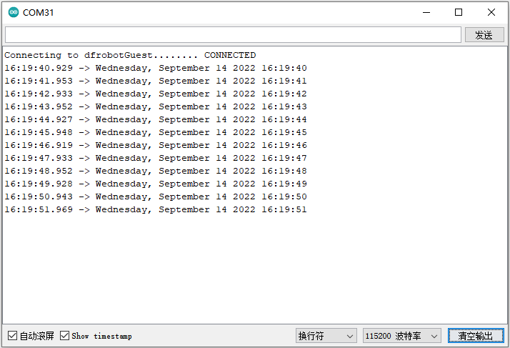
Serial.println(&timeinfo,"%A, %B %d %Y %H:%M:%S"); //按照该格式输出获取到的时间
}
void setup() {
Serial.begin(115200);
Serial.printf("Connecting to %s",ssid);
WiFi.begin(ssid,password); //连接WIFI
while(WiFi.status()!=WL_CONNECTED){ //等待连接成功
delay(500);
Serial.print(".");
}
Serial.println(" CONNECTED");
configTime(gmtOffset_sec, daylightOffset_sec, ntpServer); //配置网络时间为ESP32-E主板的系统时间
}
void loop()
{
printLocalTime(); // 打印本地时间
delay(1000);
}
程序执行结果:
当程序上传成功,可以看到当前获取的时间,如下图所示:
10.4 蓝牙
10.4.1 蓝牙基础示例
功能说明
ESP32具有蓝牙功能,本例程将示范使用两块FireBeetle 2 ESP32-E进行蓝牙通信。通过其中一块ESP32向另一块ESP32发送数据,这是使用蓝牙无线通信的最基本模型。
硬件准备:
- FireBeetle 2 ESP32-E (SKU: DFR0654)×2
示例程序
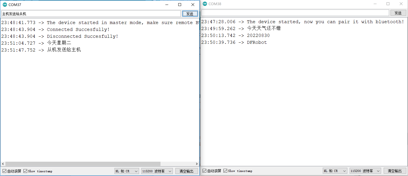
程序功能:将其中一块FireBeetle 2 ESP32-E作为主机,另一块作为从机,主机向从机发送数据,进行蓝牙无线通信。
注意:主机和从机的程序分别新建一个程序窗口,编译上传。否则打开不了两个串口。
从机程序:
#include "BluetoothSerial.h"

#if !defined(CONFIG_BT_ENABLED) || !defined(CONFIG_BLUEDROID_ENABLED)
#error Bluetooth is not enabled! Please run `make menuconfig` to and enable it
#endif

BluetoothSerial SerialBT;

void setup() {
  Serial.begin(115200);
  SerialBT.begin("ESP32_one");       //蓝牙设备名字
  Serial.println("The device started, now you can pair it with bluetooth!");
}

void loop() {
  if (Serial.available()) {
    SerialBT.write(Serial.read());
  }
  if (SerialBT.available()) {
    Serial.write(SerialBT.read());
  }
  delay(20);
}
主机程序:
#include "BluetoothSerial.h"

BluetoothSerial SerialBT;

String MACadd = "AA:BB:CC:11:22:33";
uint8_t address[6]  = {0xAA, 0xBB, 0xCC, 0x11, 0x22, 0x33};
String name = "ESP32_one";
const char *pin = "1234";  //<- 默认情况下将提供标准管脚
bool connected;

void setup() {
  Serial.begin(115200);
  SerialBT.begin("ESP32test", true);
  Serial.println("The device started in master mode, make sure remote BT device is on!");

  // 连接(address)速度快(最多10秒),连接(name)速度慢(最多30秒)
  // 首先将名称解析为地址,但它允许连接到同名的不同设备。
  // 将CoreDebugLevel设置为Info以查看设备蓝牙地址和设备名称
  connected = SerialBT.connect(name);
  if(connected) {
    Serial.println("Connected Succesfully!");
  } else {
    while(!SerialBT.connected(10000)) {
      Serial.println("Failed to connect. Make sure remote device is available and in range, then restart app.");
    }
  }
  // disconnect() 最多可能需要10秒
  if (SerialBT.disconnect()) {
    Serial.println("Disconnected Succesfully!");
  }
  // 这将重新连接到名称(如果解析,将使用地址)或与connect一起使用的地址(名称/地址)。
  SerialBT.connect();
}

void loop() {
  if (Serial.available()) {
    SerialBT.write(Serial.read());
  }
  if (SerialBT.available()) {
    Serial.write(SerialBT.read());
  }
  delay(20);
}
程序执行结果:
同时打开两个串口监视器,在其中一个串口监视器的发送一栏编辑想要发送的信息,可以在另一个串口监视器中显示,证明两个FireBeetle 2 ESP32-E开发板蓝牙通信成功。
10.4.2 蓝牙服务端
功能说明:
本节中建立了一个BLE_Server,可以为客户端提供数据和发送通知,当服务器接收到客户端发来的数据时,会将收到的数据以通知的方式发送给客户端。即例程中BLE服务端提供的通知服务只作用于将接收到的客户端数据回传。
BLEDevice
- init()
说明:创建一个BLE设备 - createServer()
说明:创建BLE服务器
BLEServer
- createService()
说明:创建一个BLE服务 - setCallbacks()
说明:创建服务器回调函数 - start()
说明:开启服务器 - getAdvertising()
说明:配置广播功能
BLEService
- createCharateristic()
说明:创建服务的特征值
BLECharacteristic
- setCallbacks()
说明:设置特征值回调函数 - addDescriptor()
说明: - setValue()
说明:设置特征值的value值 - getValue()
说明:获得特征值的value值 - notify()
说明:发通知
BLEAdvertising
- start()
说明:开启广播
硬件准备:
- FireBeetle 2 ESP32-E (SKU: DFR0654)×1
示例程序:
程序功能:建立一个BLE_Server,可以为客户端提供数据和发送通知,当服务器接收到客户端发来的数据时,会将收到的数据以通知的方式发送给客户端。
#include <BLEDevice.h>
#include <BLEServer.h>
#include <BLEUtils.h>
#include <BLE2902.h>
#define SERVICE_UUID             "DFCD0001-36E1-4688-B7F5-EA07361B26A8"
#define CHARACTERISTIC1_UUID     "DFCD000A-36E1-4688-B7F5-EA07361B26A8"
bool deviceConnected = false;
BLEServer *pServer;
BLEService *pService;
BLECharacteristic* pCharacteristic;

class MyServerCallbacks: public BLEServerCallbacks {
    void onConnect(BLEServer* pServer) {
      deviceConnected = true;
    };

    void onDisconnect(BLEServer* pServer) {
      deviceConnected = false;
    }
};
class MyCallbacks: public BLECharacteristicCallbacks {
    void onWrite(BLECharacteristic *pCharacteristic) {
      std::string value = pCharacteristic->getValue();

      if (value.length() > 0) {
        Serial.println("*********");
        Serial.print("New value: ");
        for (int i = 0; i < value.length(); i++){
          Serial.print(value[i]);
        }
        Serial.println();
        Serial.println("*********");
        pCharacteristic->notify();
      }
    }
};
void setupBLE()
{
  BLEDevice::init("DFRobot_ESP32");   //创建BLE设备
  pServer = BLEDevice::createServer();   //创建BLE服务器
  pServer->setCallbacks(new MyServerCallbacks());   //设置服务器的回调函数
  pService = pServer->createService(SERVICE_UUID); //创建BLE服务
  pCharacteristic = pService->createCharacteristic(
                                                 CHARACTERISTIC1_UUID,
                                                 BLECharacteristic::PROPERTY_READ|
                                                 BLECharacteristic::PROPERTY_NOTIFY|
                                                 BLECharacteristic::PROPERTY_WRITE);   //创建服务的特征值
  pCharacteristic->setCallbacks(new MyCallbacks());    //设置特征值的回调函数
  pCharacteristic->addDescriptor(new BLE2902());
  pCharacteristic->setValue("Hello DFRobot");
  pService->start();
  BLEAdvertising *pAdvertising = pServer->getAdvertising();
  pAdvertising->start();
}
void setup() {
  Serial.begin(115200);
  setupBLE();
}

void loop() {
   delay(3000);
}
程序执行结果:
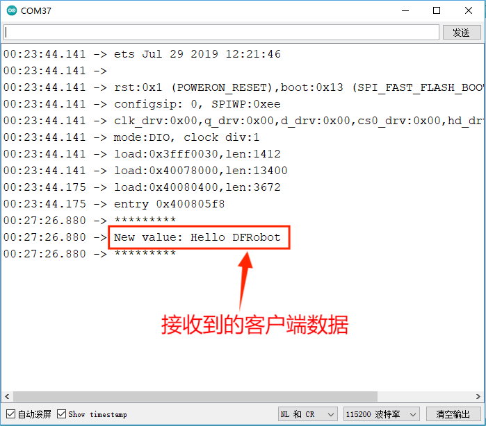
使用FireBeetle 2 ESP32-E作为BLE的服务端,客户端可以是手机。在手机应用商店上安装蓝牙助手LightBlue,与ESP32-E模块建立BLE连接。这里对iPhone手机提供的Light Blue操作进行演示,Android系统的手机也有类似的蓝牙软件助手。
手机客户端操作如下:
- 第一步,连接DFRobot_ESP32
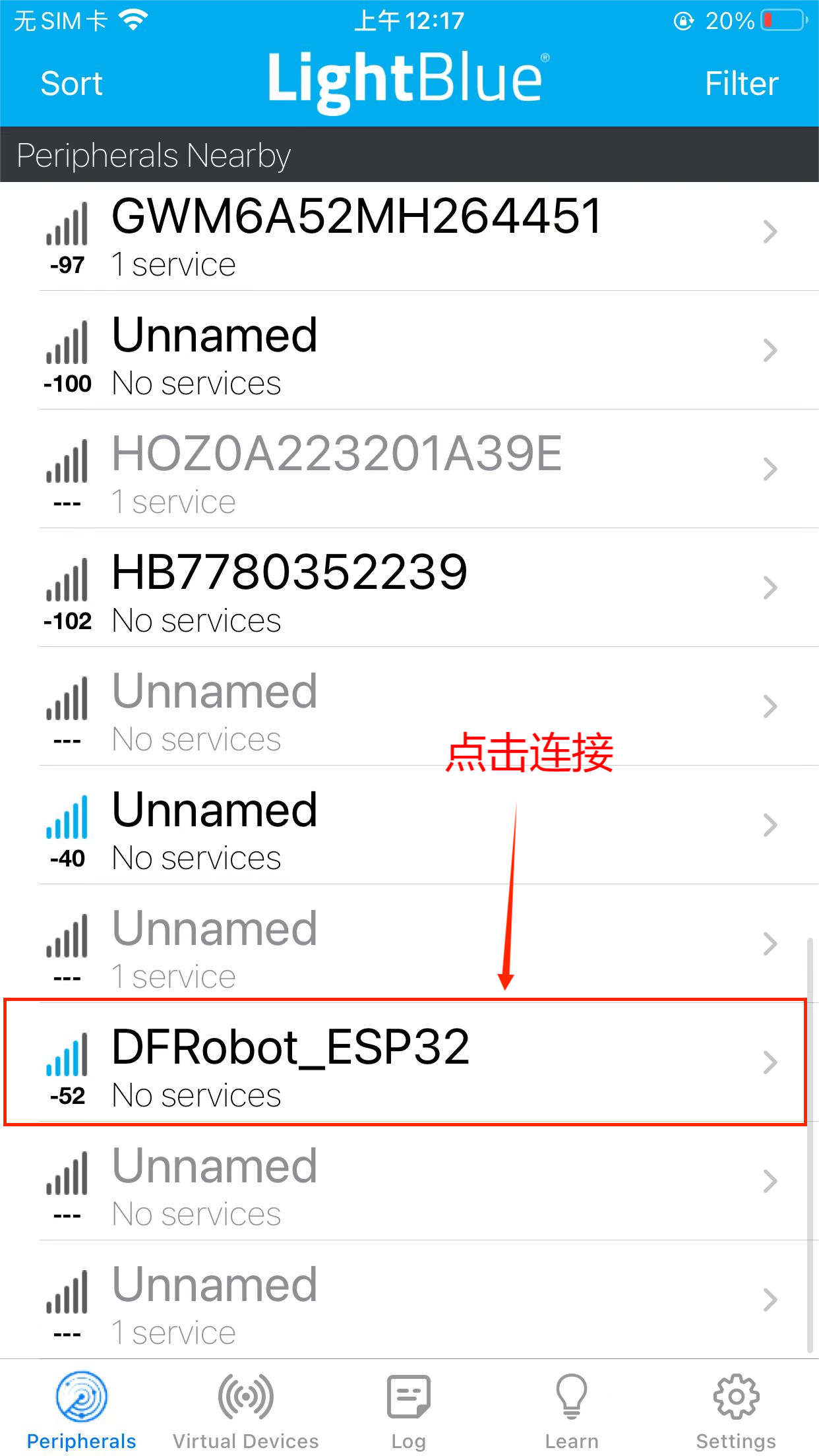
- 第二步,点击图中所示
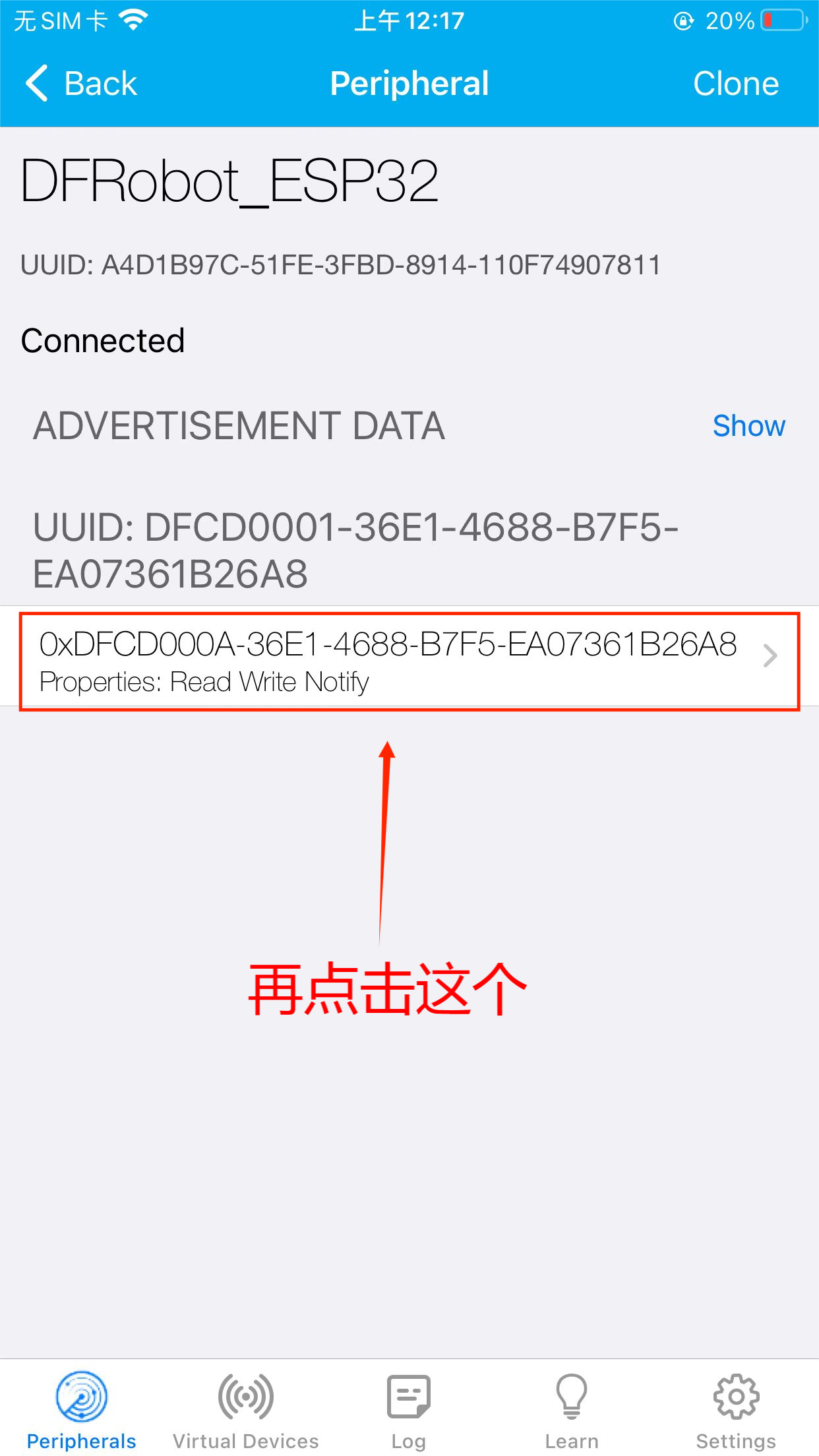
- 第三步,发送数据给服务端
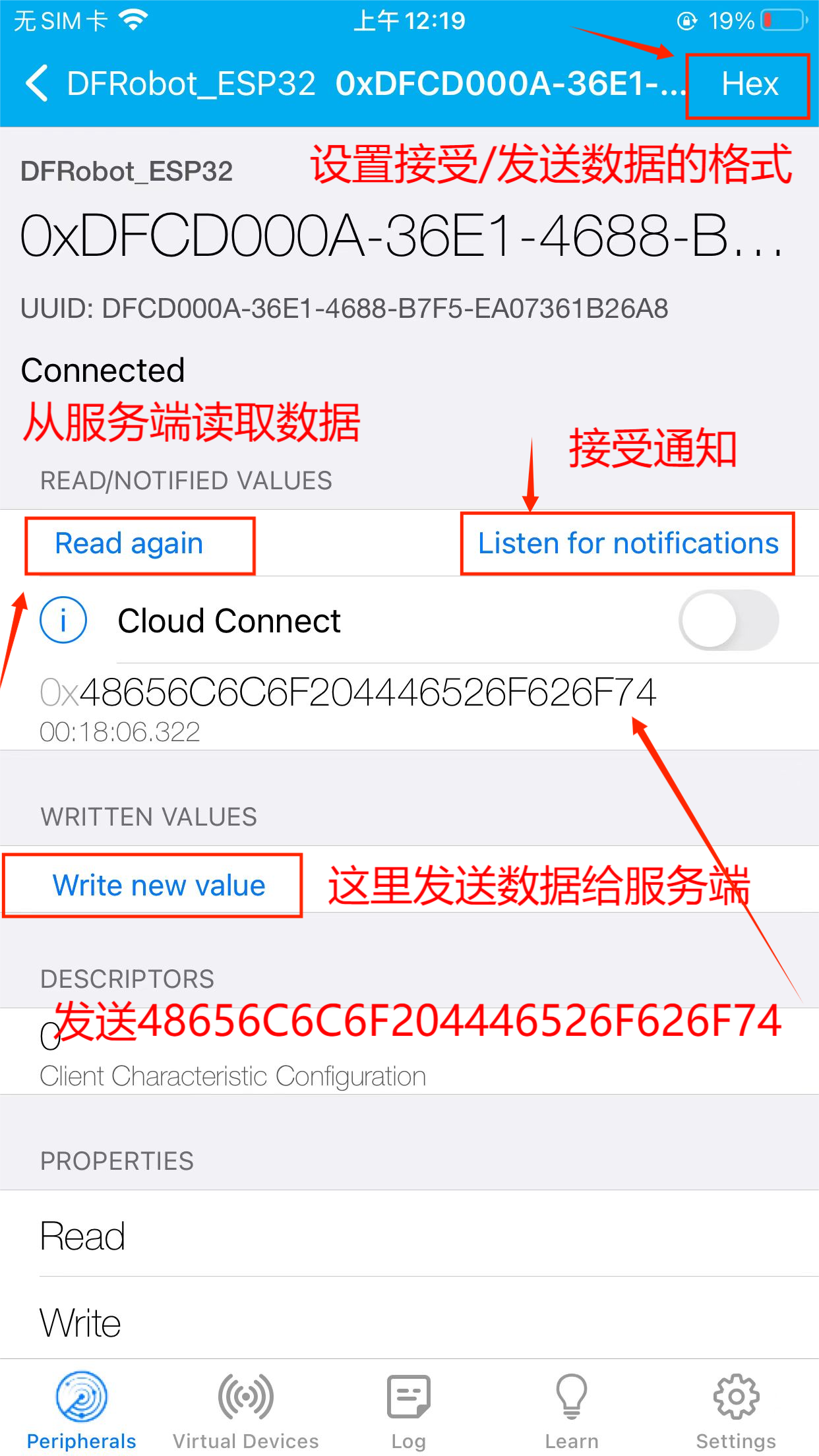
- 第四步,可以看到已发送的数据
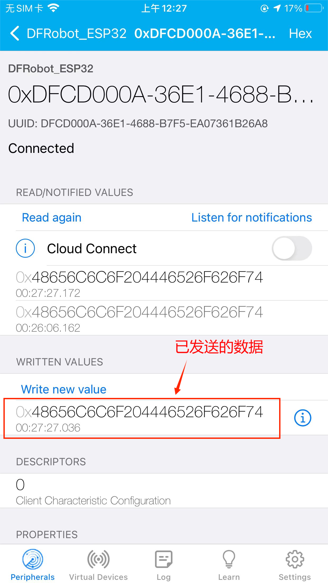
- 第五步,在串口可以看到接收到的客户端数据
10.5 阿里云loT
10.5.1 阿里云是什么
阿里云IoT致力于实现万物互联的美好世界,为生态合作伙伴提供基于云端一体化、安全物联网基础平台等,在通过该平台高效连接,管理设备的同时,其开放能力使合作伙伴更高效、低成本地构建各种创新的物联网应用场景。 阿里云物联网平台为设备提供安全可靠的连接通信能力,向下连接海量设备,支撑设备数据采集上云;向上提供云端API,指令数据通过API调用下发至设备端,实现远程控制。 此外阿里云IoT还提供了丰富的开发服务,用户可以直接在该平台上搭建Web可视化、移动应用、服务开发等开发服务,这降低了物联网项目开发的难度,有了它,用户无需任何专业的开发技巧也可开发自己的项目。
阿里云物联网的开发框架
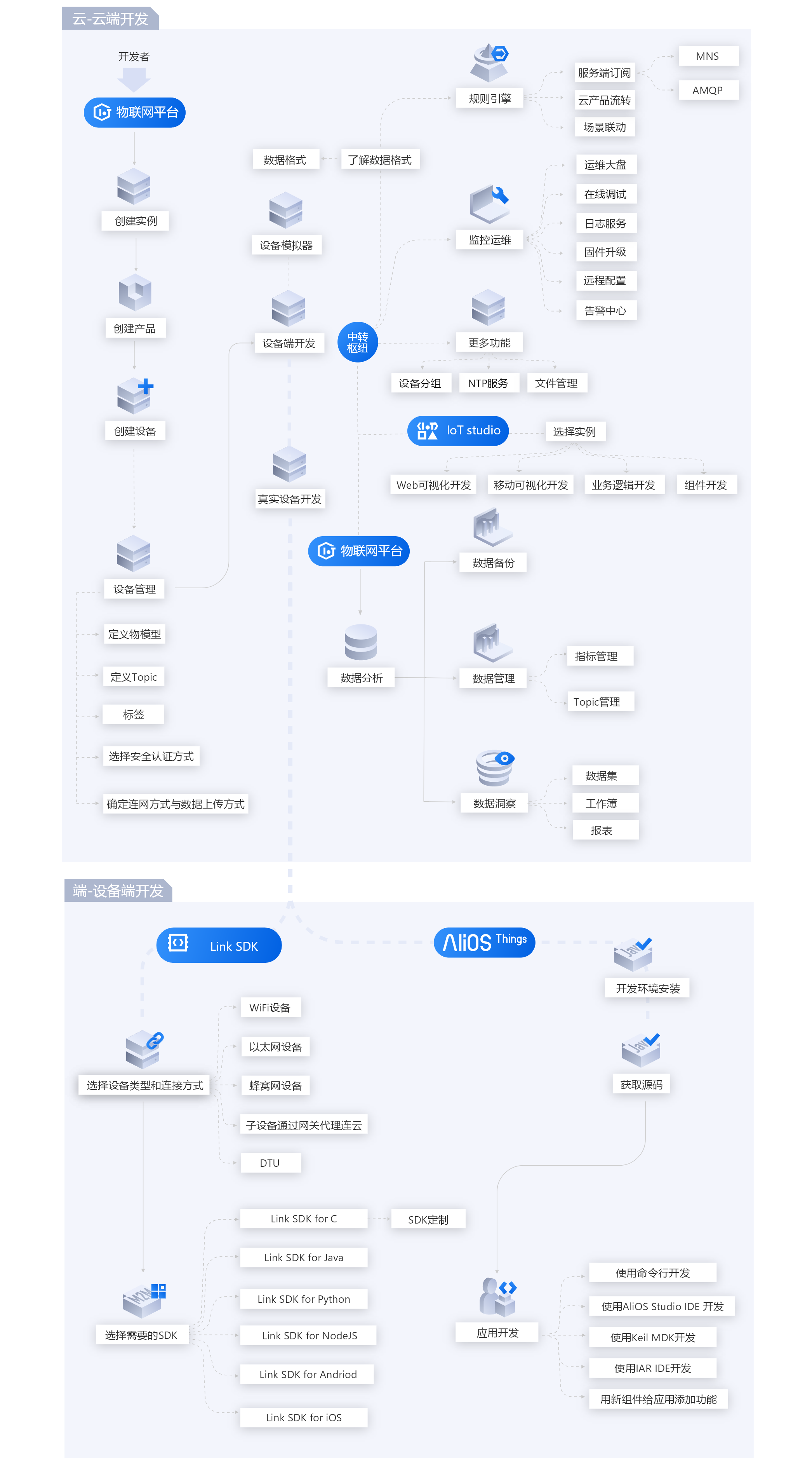
什么是物联网平台
阿里云物联网平台为设备提供安全可靠的连接通信能力,向下连接海量设备,支撑设备数据采集上云;向上提供云端API,服务端通过调用云端API将指令下发至设备端,实现远程控制。
物联网平台消息通信流程图如下:
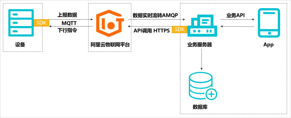
实现设备消息的完整通信流程,需要您完成设备端的设备开发、云端服务器的开发(云端SDK的配置)、数据库的创建、手机App的开发。
阿里云物联网详细手册请点击: https://help.aliyun.com/product/30520.html?spm=a2c4g.11174283.6.540.371c166845oVZh
10.5.2 智慧灯光
本节中,将在阿里云物联网平台创建一个名字为FireBeetle LED的产品,在产品中新建一个ESP32-E设备。在物联网应用开发IoT Studio平台新建一个Web UI,通过操作UI上的按钮控制FireBeetle 2 ESP32-E主板上LED的亮灭,同时将 LED的状态显示到UI界面。
10.5.2.1 操作步骤
- 注册并登陆阿里云账号
浏览器访问网址 https://www.aliyun.com 进入阿里云主界面,点击登陆,在密码登陆栏点击免费注册,进入阿里云账号注册界面(若已有账号可直接登陆),按要求完成注册,并且进行实名认证即可。
- 注册完成后,点击 产品 -> 物联网IoT -> 物联网云服务 -> 物联网平台
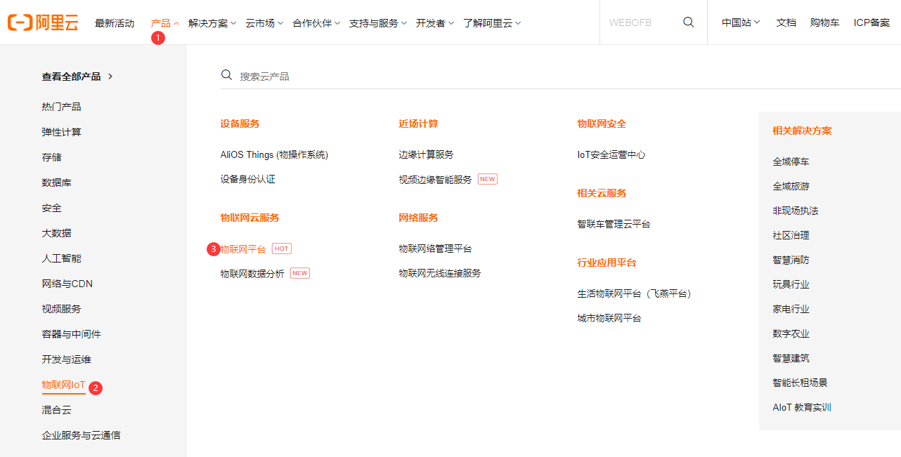
- 进入物联网平台后,点击进入控制台。

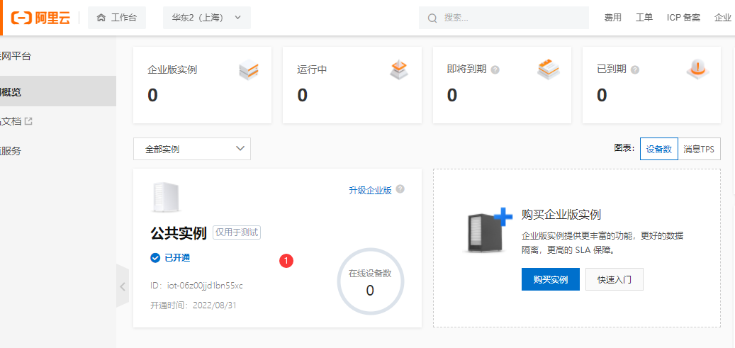
- 点击公共实例。目前开通的服务只有公共实例,便于原型调试或个人用户使用。企业实例需要额外付费。
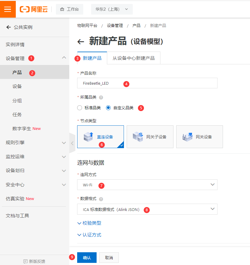
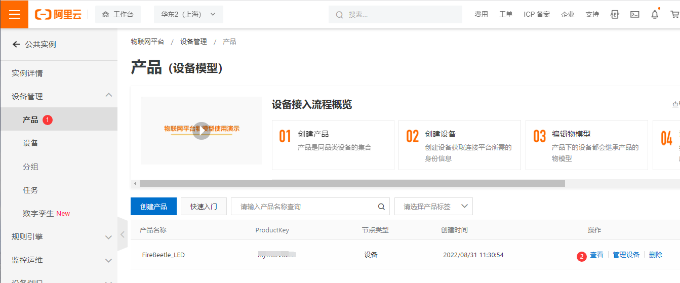
- 跳转到新页面后,在左侧菜单栏点击设备管理,点击产品,点击创建产品,弹出新建产品页面。产品名称命名为 “FireBeetle_LED”,自定义品类,直连设备,联网方式 Wi-Fi,数据格式JSON。点击确认。
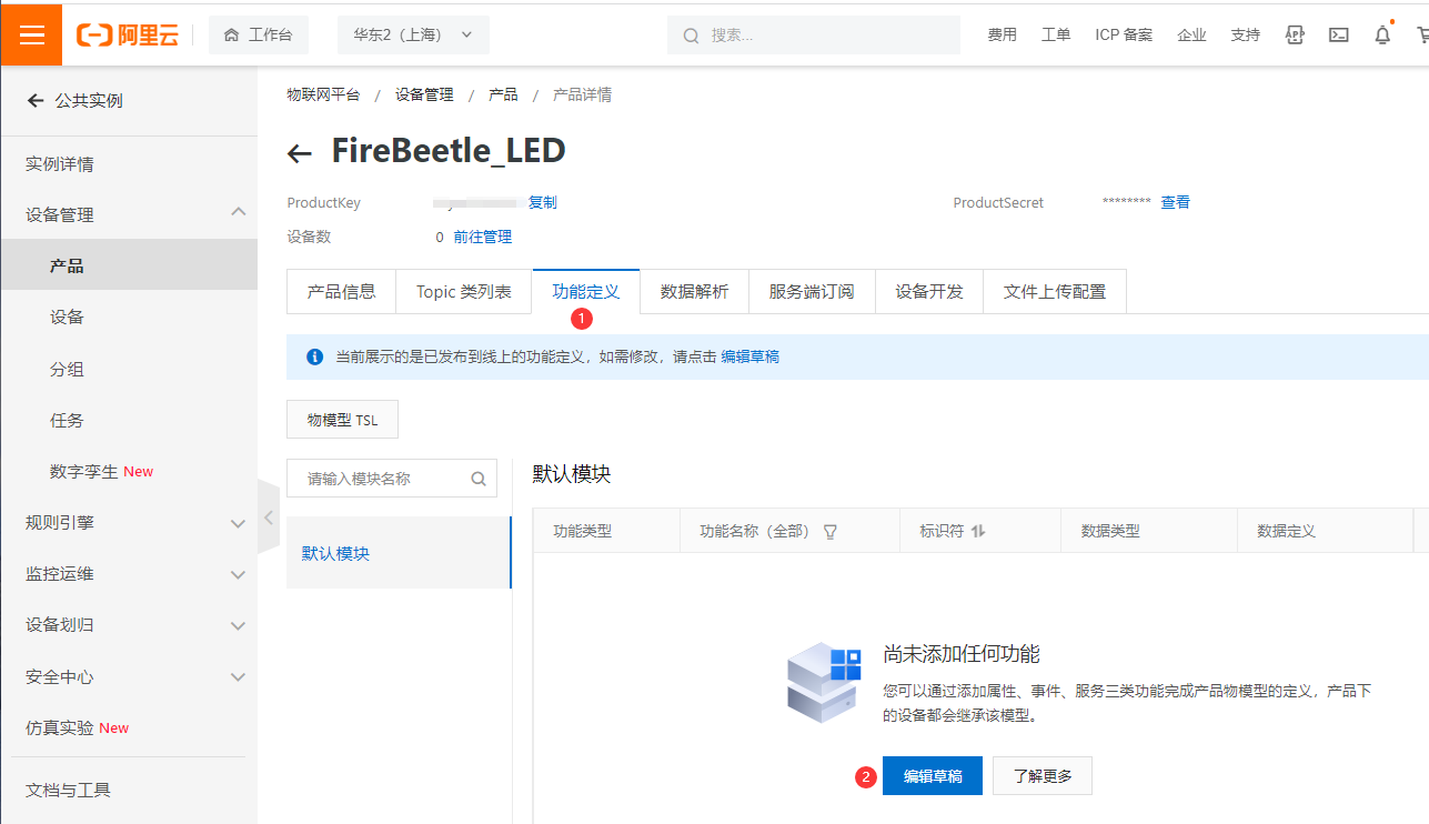
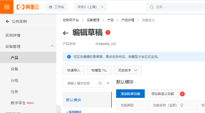
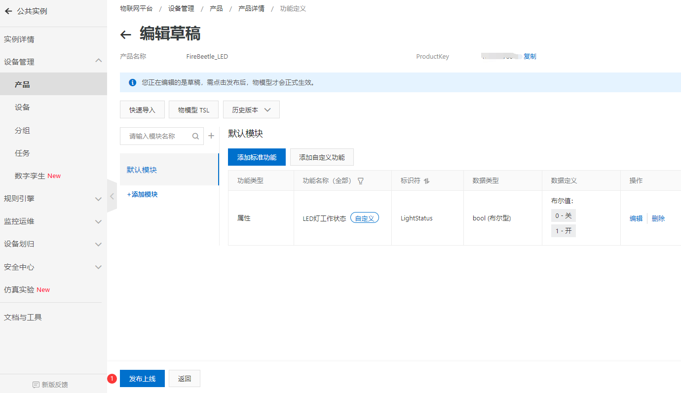
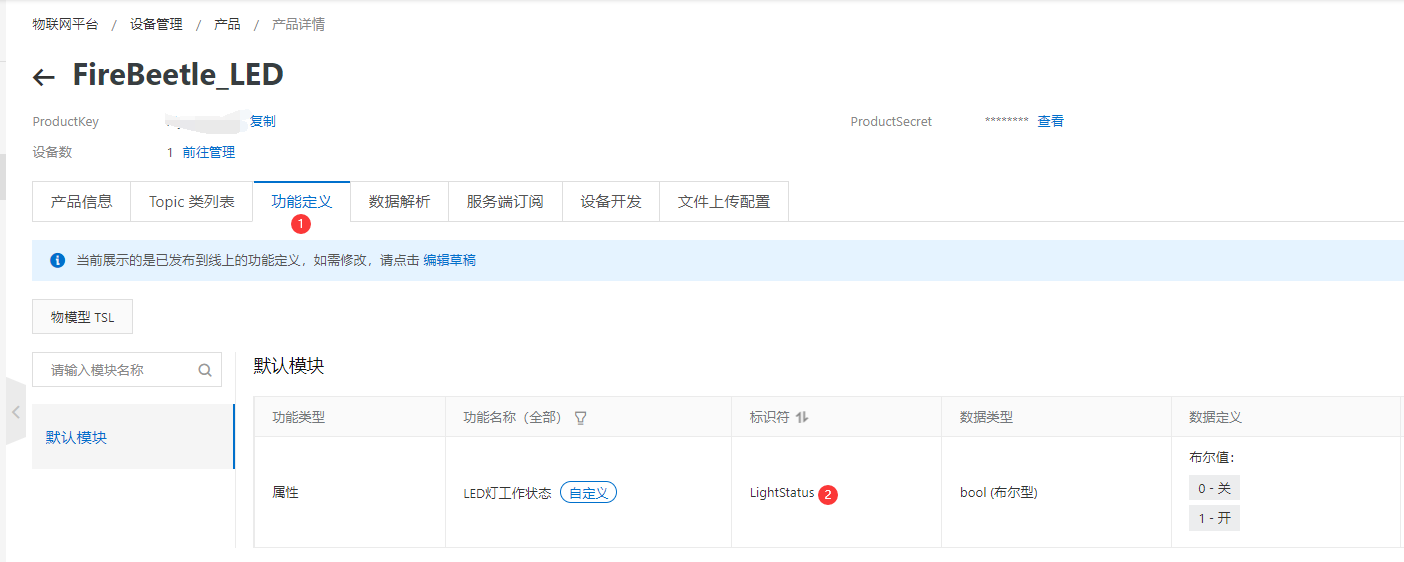
- 点击产品,再点击新建的“FireBeetle_LED”产品的查看操作,点击 功能定义 -> 编辑草稿。
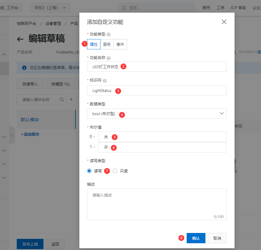
- 添加自定义功能,为产品定义一个LED灯工作状态的属性,灯有两种工作状态:开和关,可用布尔型表示,其中0代表灯关,1代表灯开。点击确认。
- 点击发布上线,发布物模型。可看到自定义LED功能定义。
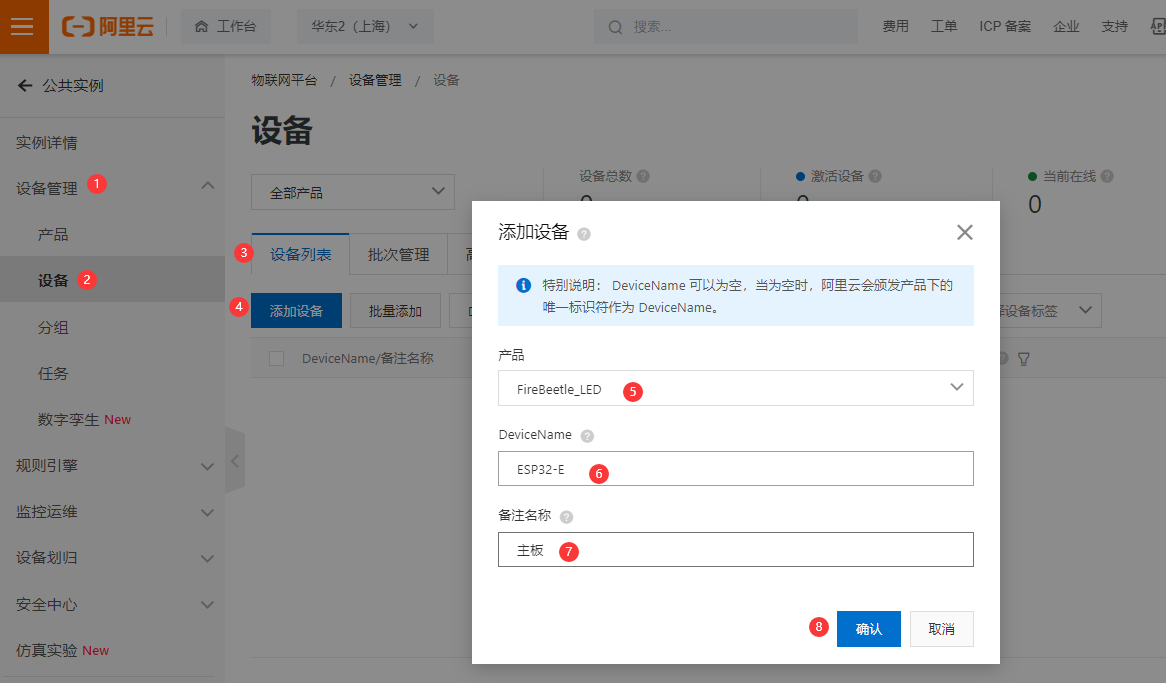
- 为 FireBeetle_LED产品添加设备ESP32-E,点击确定。
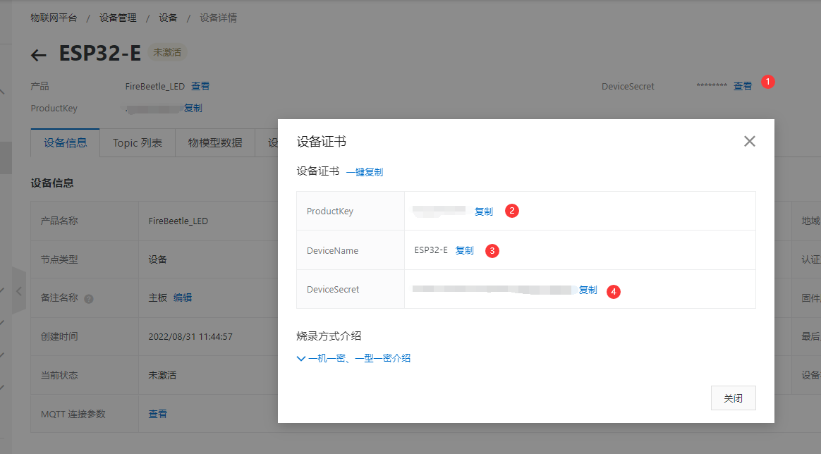
- 复制设备证书的 ProductKey,DeviceName,DeviceSecret,保存到记事本,用于FireBeetle 2 ESP32-E主板固件开发。
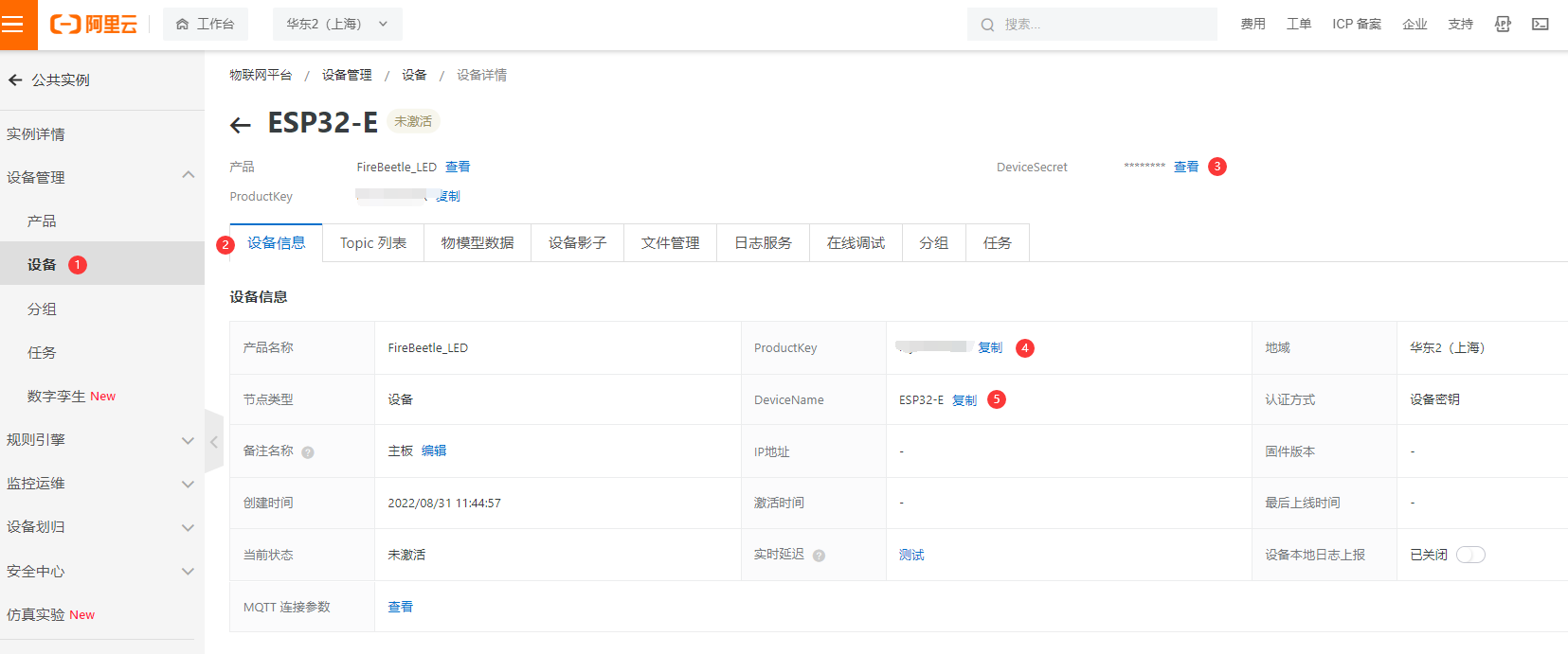
- 设备证书包含ProductKey、DeviceName和DeviceSecret,是设备与物联网平台进行通信的重要身份认证。后续设备接入,需设置此信息,请复制后妥善保管。
| 参数 | 说明 |
|---|---|
| ProductKey | 设备所属产品的ProductKey,即物联网平台为产品颁发的全局唯一标识符。 |
| DeviceName | 设备在产品内的唯一标识符。DeviceName与设备所属产品的ProductKey组合,作为设备标识,用来与物联网平台进行连接认证和通信。 |
| DeviceSecret | 物联网平台为设备颁发的设备密钥,用于认证加密。需与DeviceName成对使用。 |
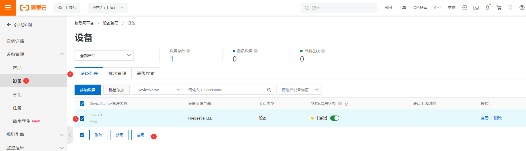
- 点击启用这个设备。
10.5.2.2 软件准备
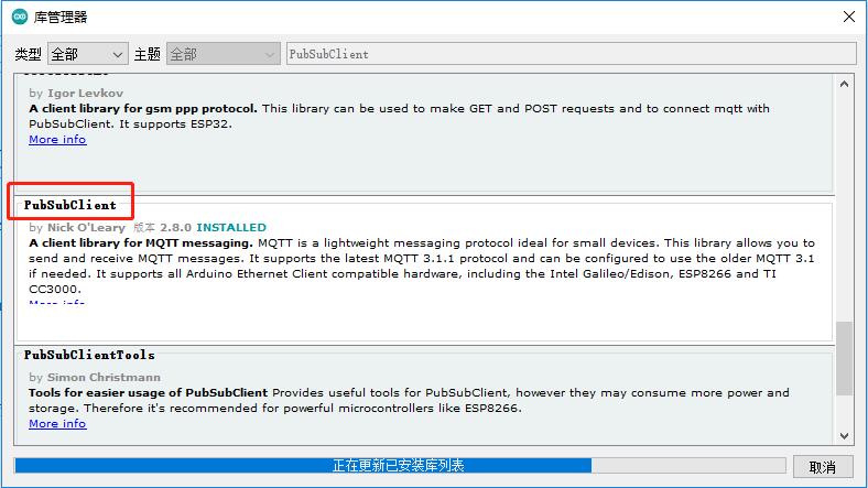
- DFRobot_Aliyun库依赖ArduinoJson库和PubSubClient库,在使用之前需要在Arduino IDE库管理器中安装这两个库。
- 只需转到Sketch > Include Library > Manage Libraries ,搜索库的名字 ArduinoJson和PubSubClient,点击安装
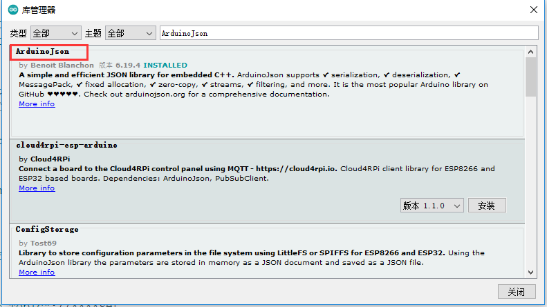
ArduinoJson 库详细教程:https://arduinojson.org/v6/example/parser/
- 参考DFRobot_Aliyun 例子程序,修改以下参数:
1、连接WiFi的信息
/*配置WIFI名和密码*/
const char * WIFI_SSID     = "WIFI_SSID";
const char * WIFI_PASSWORD = "WIFI_PASSWORD";
2、设备证书信息
/*配置设备证书信息*/
String ProductKey = "you Product Key";
String ClientId = "12345"; // 自定义ID
String DeviceName = "you Device Name";
String DeviceSecret = "you Device Secret";
3、物模型产品标识符
/*需要操作的产品标识符*/
String Identifier = "LightStatus";
4、Topicc
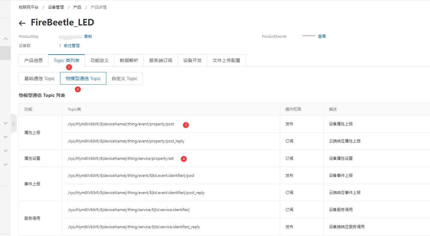
/*需要上报和订阅的两个TOPIC*/
const char * subTopic = "/sys/a1MqGxxxxxx/ESP32-E/thing/service/property/set"; //****set
const char * pubTopic = "/sys/a1MqGxxxxxx/ESP32-E/thing/event/property/post";  //******post
ESP32-E是刚才新建的设备名称。
10.5.2.3 示例程序
程序功能:在物联网IOT平台上控制FireBeetle 2 ESP32-E设备板载的LED灯的亮灭。
#include <WiFi.h>
#include <PubSubClient.h>
#include <ArduinoJson.h>
#include "DFRobot_Aliyun.h"
#define BEDROOD_LIGHT  D9
/*配置WIFI名和密码*/
const char * WIFI_SSID     = "WIFI_SSID";
const char * WIFI_PASSWORD = "WIFI_PASSWORD";

/*配置设备证书信息*/
String ProductKey = "your Product Key";
String ClientId = "12345";/*自定义ID*/
String DeviceName = "your Device Name";
String DeviceSecret = "your Device Secret";

/*配置域名和端口号*/
String ALIYUN_SERVER = "iot-as-mqtt.cn-shanghai.aliyuncs.com";
uint16_t PORT = 1883;

/*需要操作的产品标识符*/
String Identifier = "LightStatus";

/*需要上报和订阅的两个TOPIC*/
const char * subTopic = "/sys/hl********/ESP32-E/thing/service/property/set";//****set
const char * pubTopic = "/sys/hl********/ESP32-E/thing/event/property/post";//******post

DFRobot_Aliyun myAliyun;
WiFiClient espClient;
PubSubClient client(espClient);

static void openLight(){
 digitalWrite(BEDROOD_LIGHT, HIGH);
}

static void closeLight(){
 digitalWrite(BEDROOD_LIGHT, LOW);
}

void connectWiFi(){
 Serial.print("Connecting to ");
 Serial.println(WIFI_SSID);
 WiFi.begin(WIFI_SSID,WIFI_PASSWORD);
 while(WiFi.status() != WL_CONNECTED){
   delay(500);
   Serial.print(".");
 }
 Serial.println();
 Serial.println("WiFi connected");
 Serial.print("IP Adderss: ");
 Serial.println(WiFi.localIP());
}

void callback(char * topic, byte * payload, unsigned int len){
 Serial.print("Recevice [");
 Serial.print(topic);
 Serial.print("] ");
 for (int i = 0; i < len; i++){
   Serial.print((char)payload[i]);
 }
 Serial.println();
 StaticJsonBuffer<300> jsonBuffer;
 JsonObject& root = jsonBuffer.parseObject((const char *)payload);
 if(!root.success()){
   Serial.println("parseObject() failed");
   return;
 }
 const uint16_t LightStatus = root["params"][Identifier];
 if(LightStatus == 1){
   openLight();
 }else{
   closeLight();
 }
 String tempMseg = "{\"id\":"+ClientId+",\"params\":{\""+Identifier+"\":"+(String)LightStatus+"},\"method\":\"thing.event.property.post\"}";
 char sendMseg[tempMseg.length()];
 strcpy(sendMseg,tempMseg.c_str());
 client.publish(pubTopic,sendMseg);
}

void ConnectAliyun(){
while(!client.connected()){
  Serial.print("Attempting MQTT connection...");
  /*根据自动计算的用户名和密码连接到Alinyun的设备,不需要更改*/
  if(client.connect(myAliyun.client_id,myAliyun.username,myAliyun.password)){
    Serial.println("connected");
    client.subscribe(subTopic);
  }else{
    Serial.print("failed, rc=");
    Serial.print(client.state());
    Serial.println(" try again in 5 seconds");
    delay(5000);
  }
}
}
void setup(){
Serial.begin(115200);
pinMode(BEDROOD_LIGHT,OUTPUT);

/*连接WIFI*/
connectWiFi();

/*初始化Alinyun的配置,可自动计算用户名和密码*/
myAliyun.init(ALIYUN_SERVER,ProductKey,ClientId,DeviceName,DeviceSecret);

client.setServer(myAliyun.mqtt_server,PORT);

/*设置回调函数,当收到订阅信息时会执行回调函数*/
client.setCallback(callback);

/*连接到Aliyun*/
ConnectAliyun();

/*开机先关灯*/
closeLight();

/*上报关灯信息*/
client.publish(pubTopic,("{\"id\":"+ClientId+",\"params\": {\""+Identifier+"\":0},\"method\":\"thing.event.property.post\"}").c_str());
}

void loop(){
if(!client.connected()){
  ConnectAliyun();
}
client.loop();
}
10.5.2.4 程序执行结果
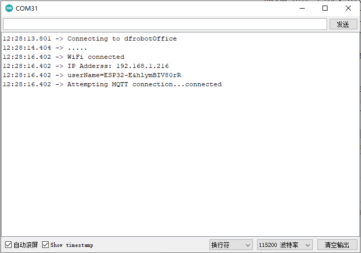
- 设备上电后,串口显示已经连接到WiFi,并且显示已经连接到阿里云物联网。
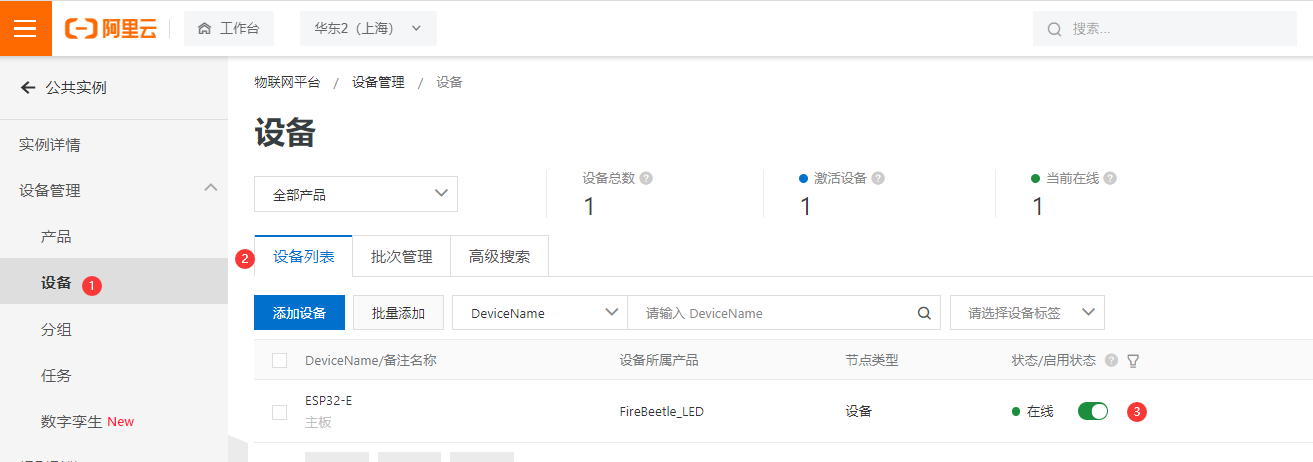
- 此时在阿里云物联网 设备列表可看到产品已经在线
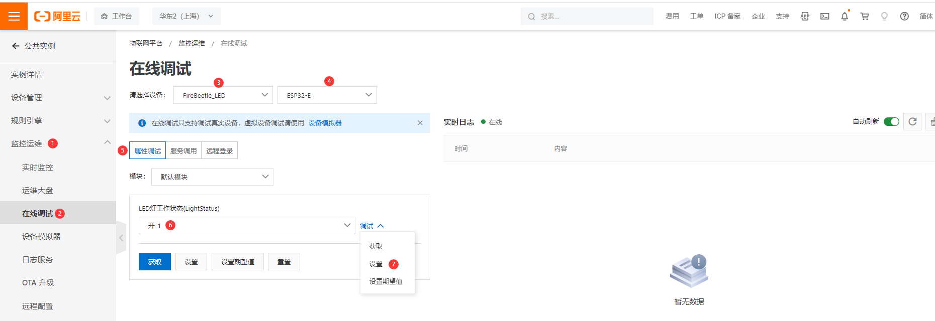
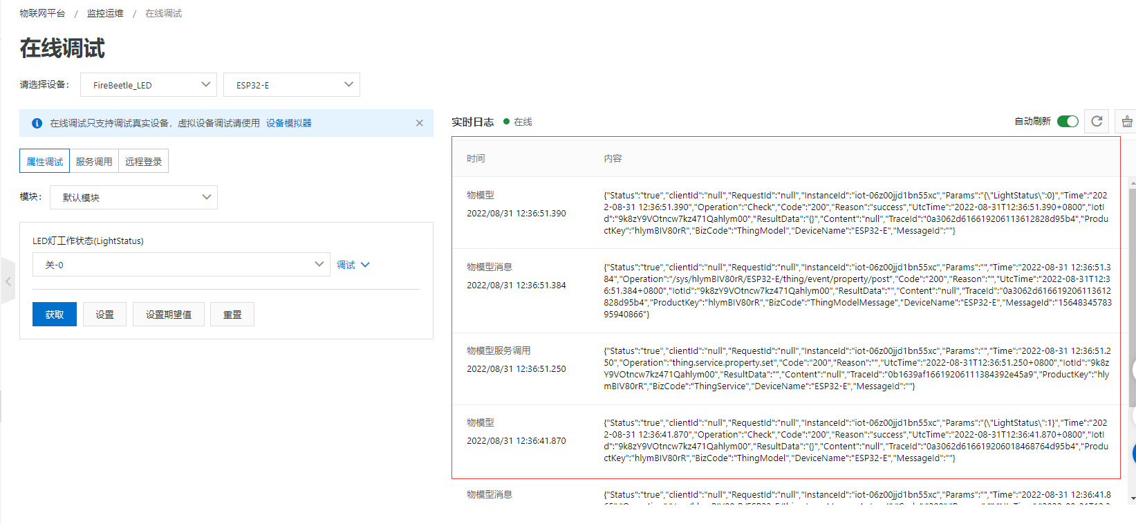
- 进入在线调试界面,选择要操作的设备。LED状态选择 开-1,调试下拉菜单点击设置。此时可看到主板上的灯被点亮。LED状态选择 关-0,点击设置,主板上的LED灯熄灭。
- LED的状态显示到UI界面。
10.6. IFTTT
10.6.1 什么是IFTTT
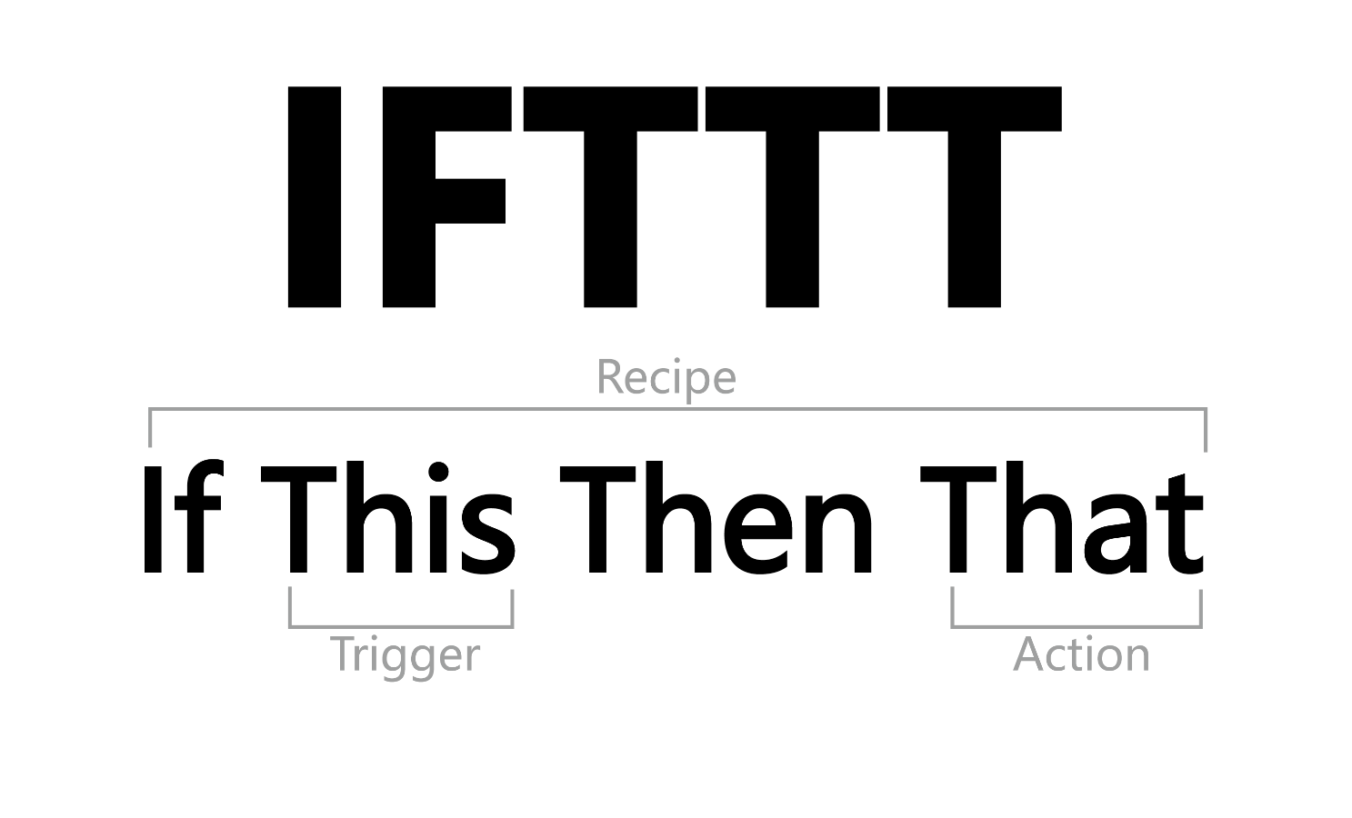
IFTTT是If This Then That的缩写,事实上是让你的网络行为能够引发连锁反应、让你使用更为方便,其宗旨是“Put the internet to work for you”(让互联网为你服务)。IFTTT旨在帮助人们利用各网站的开放API,监控用户设置的Trigger,如果 Trigger 被触发则执行用户设置的Action,通常我们可以创建N个Applet,来满足我们的各种自动化需求。
10.6.2 数据邮件
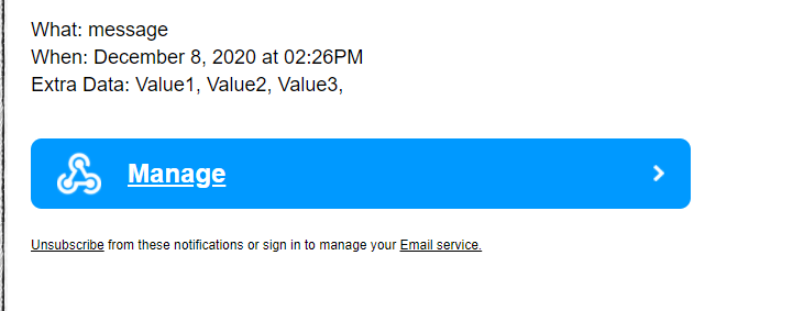
在这个应用中,用到了Webhooks和Email这两个小程序,实现了每10秒发送一次HTTP POST请求,Trigger被触发,于是执行Action,发送数据邮件。
10.6.2.1 操作步骤
-
进入IFTTT官网:https://ifttt.com/
-
注册账户,这里用的是邮箱注册
-
配置IFTTT
-
创建Trigger
-
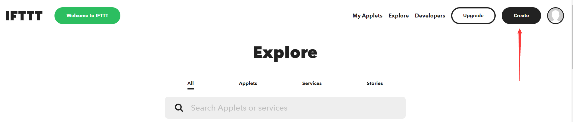
登录IFTTT,点击“Create”创建你的小程序。
-
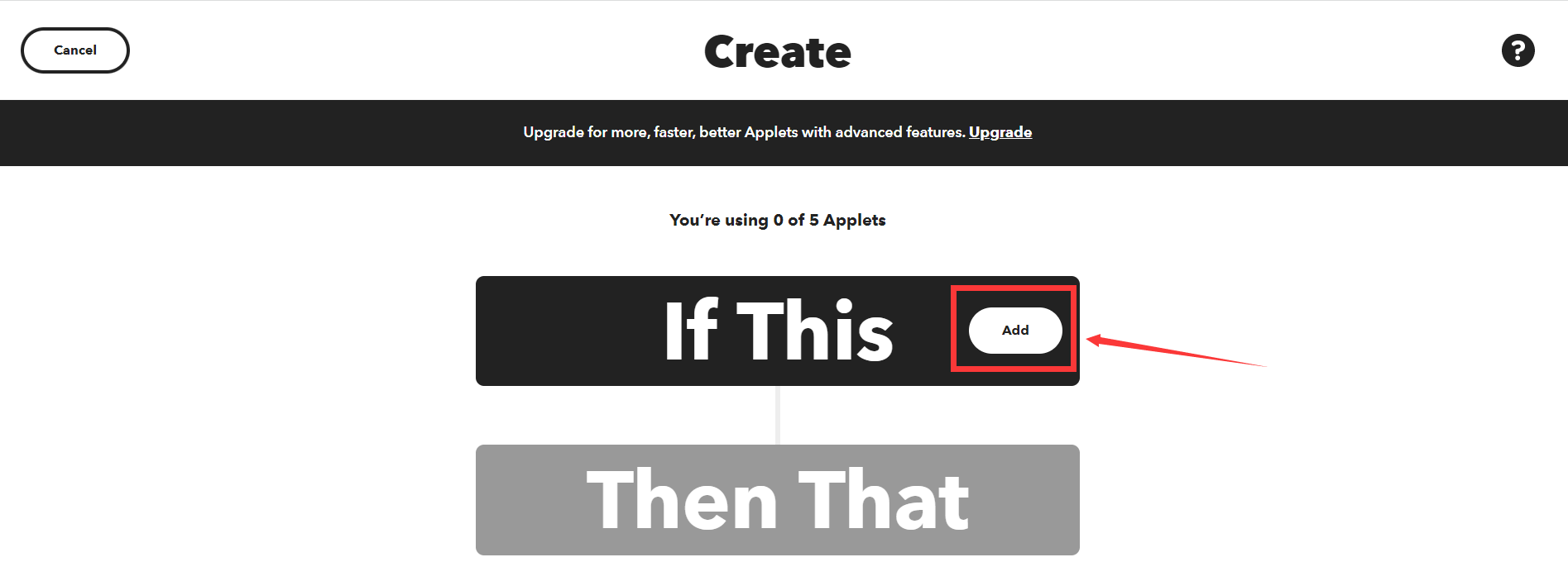
点击“If This”中的“Add。
-
输入“Webhooks”。
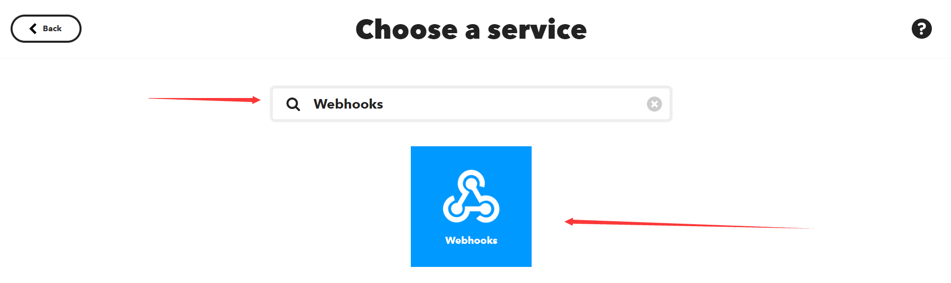
-
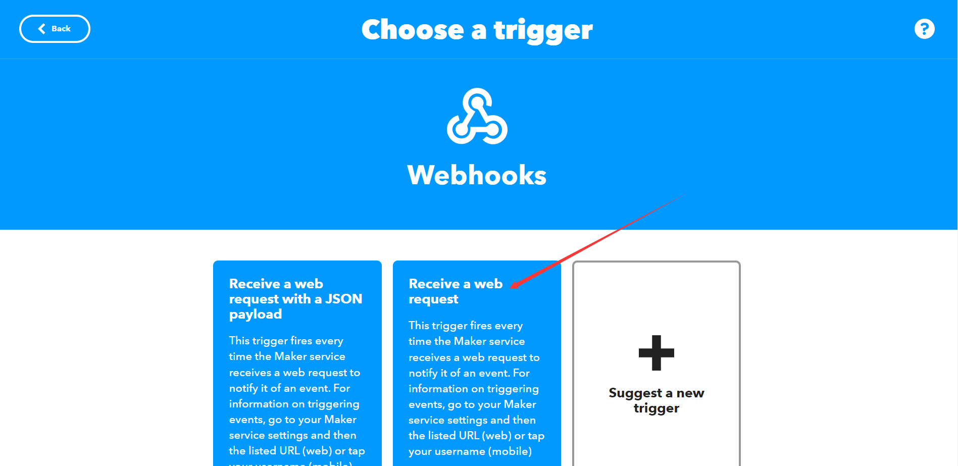
点击进入“Webhooks”,选择“Receive a web request”。
-
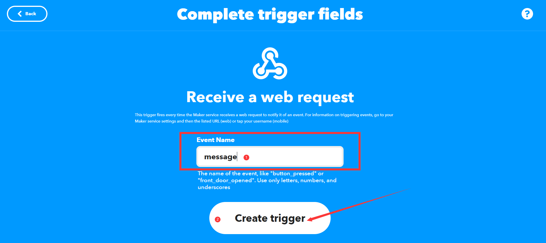
然后创建我们的Event Name “message”,点击”Create trigger“完成”this”的设置。
-
-
创建Action
-
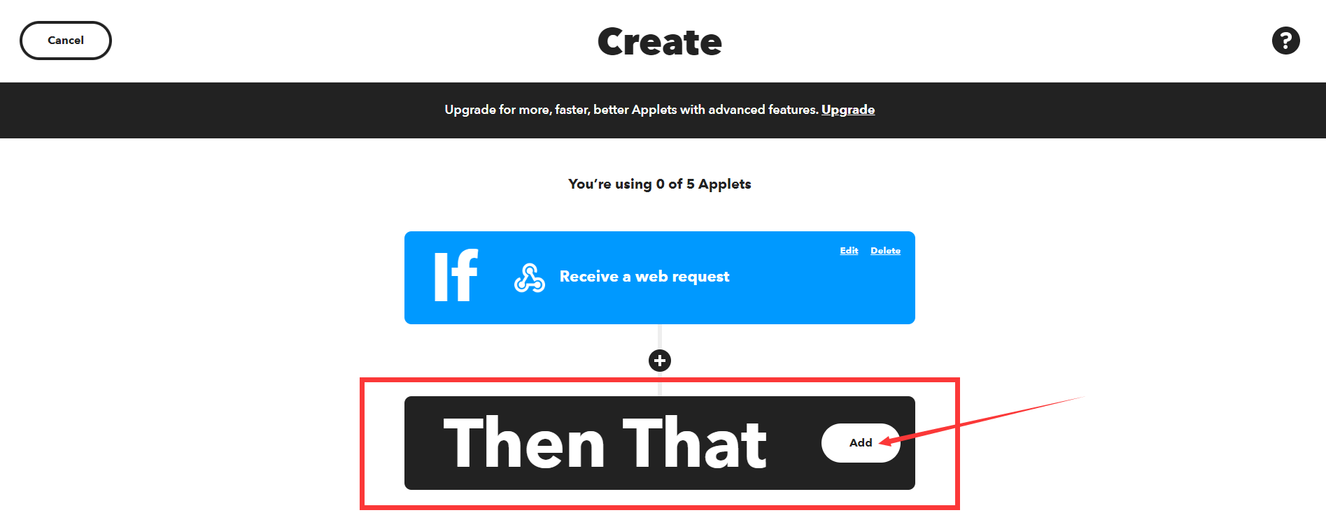
设置好触发“this”后,继续添加动作指令“that”,点击“Then That”中的”Add“。
-
搜索并点击"Email"。
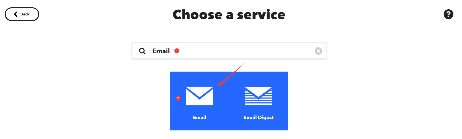
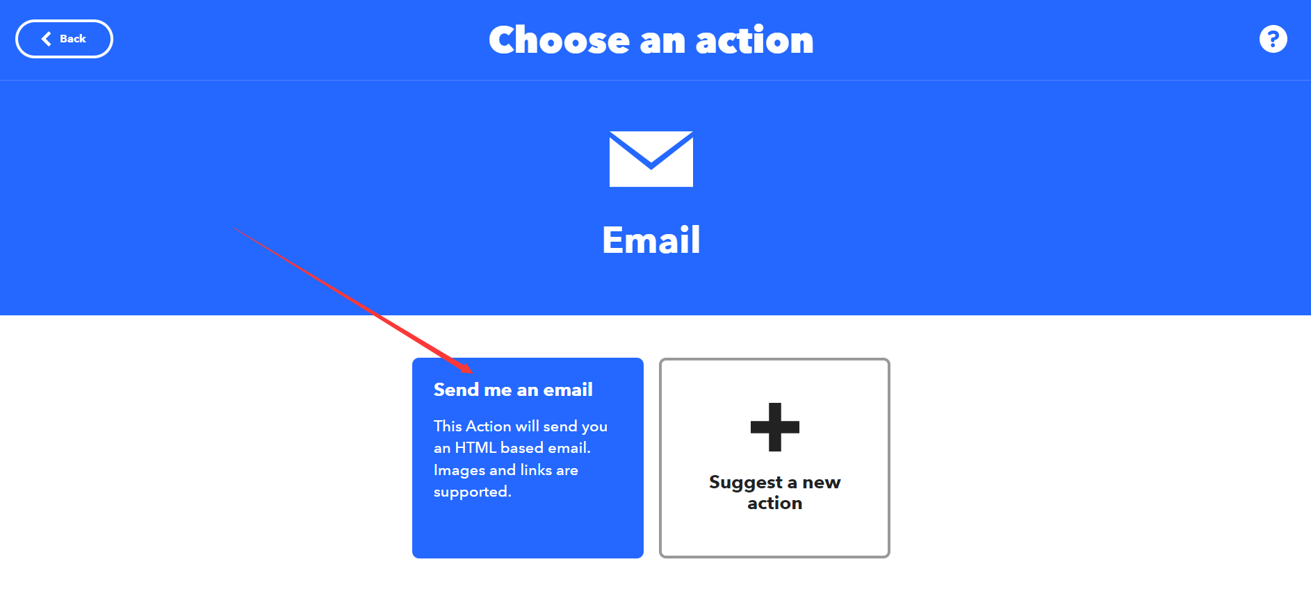
-
然后选择"Send me an email"。
-
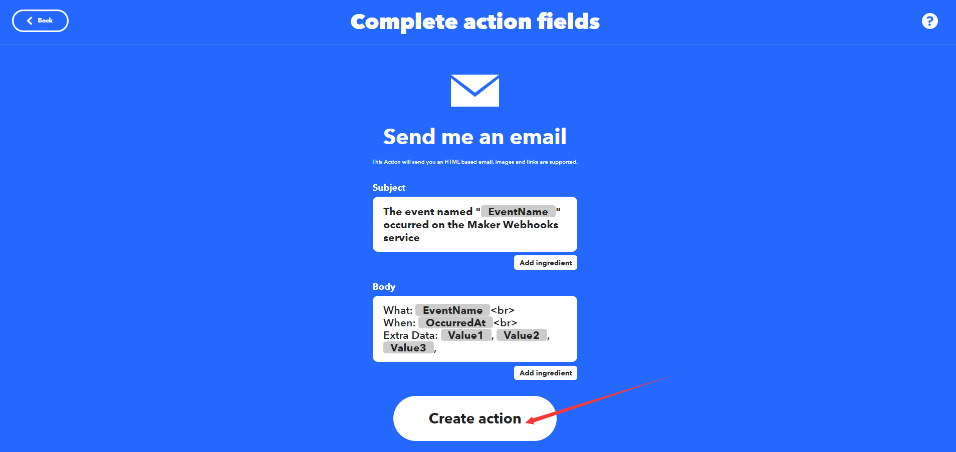
-
选择之后就可以编辑邮件内容了,在"subject"中输入邮件主题,在"Body"中输入邮件内容,然后点击"Create action"完成创建。
-
点击"Continue"。
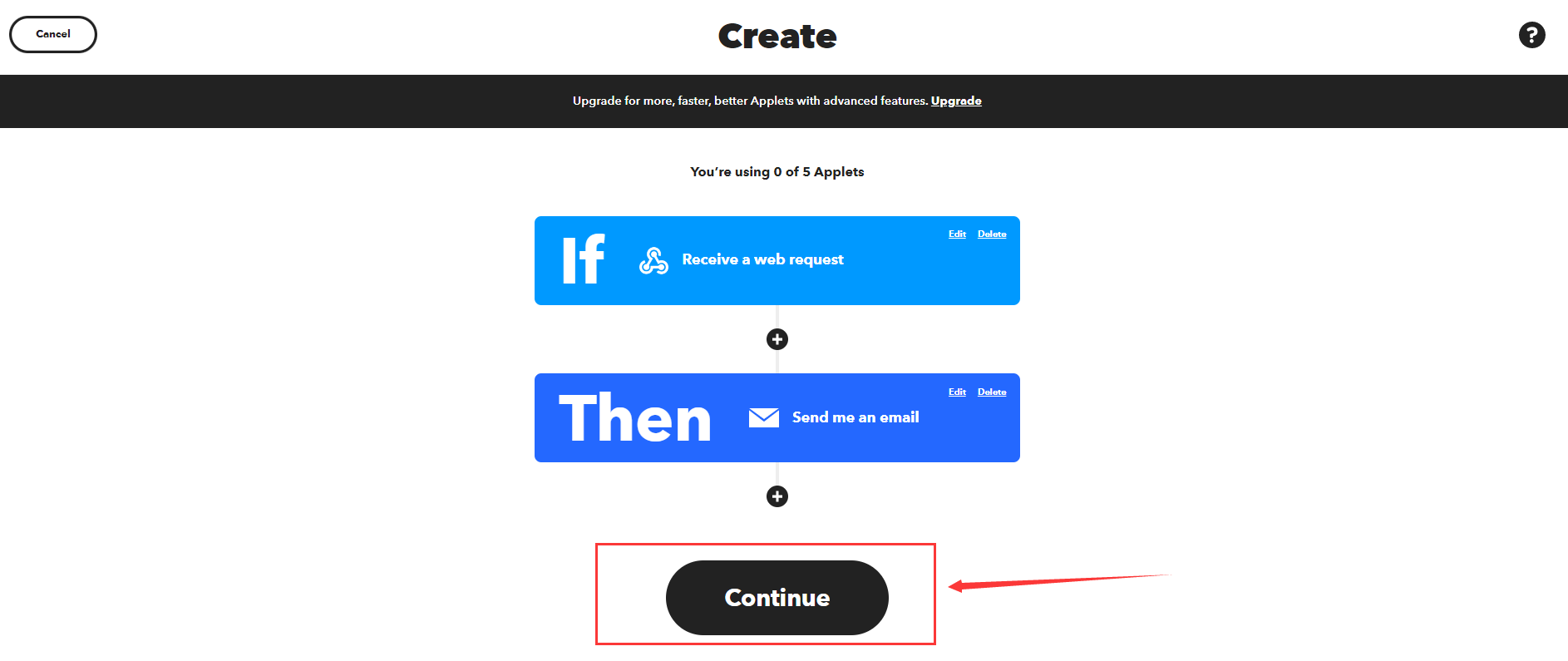
-
进行Review,然后点击"Finish"完成创建。

-
找到IFTTT_Key
- 点击"My services"
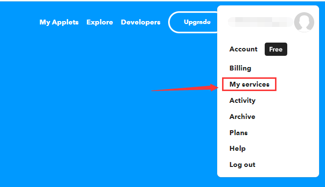
- 点击"Webhooks"
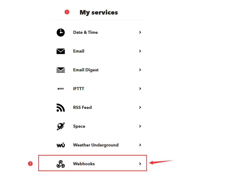
- 点击"Documentation"
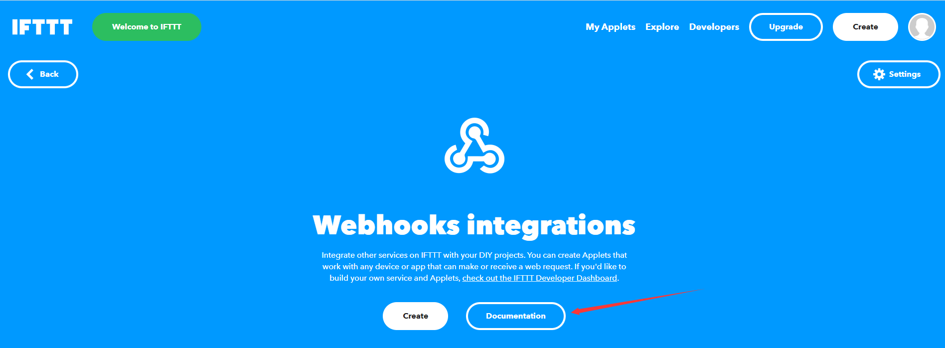
- 在图示位置复制密钥。
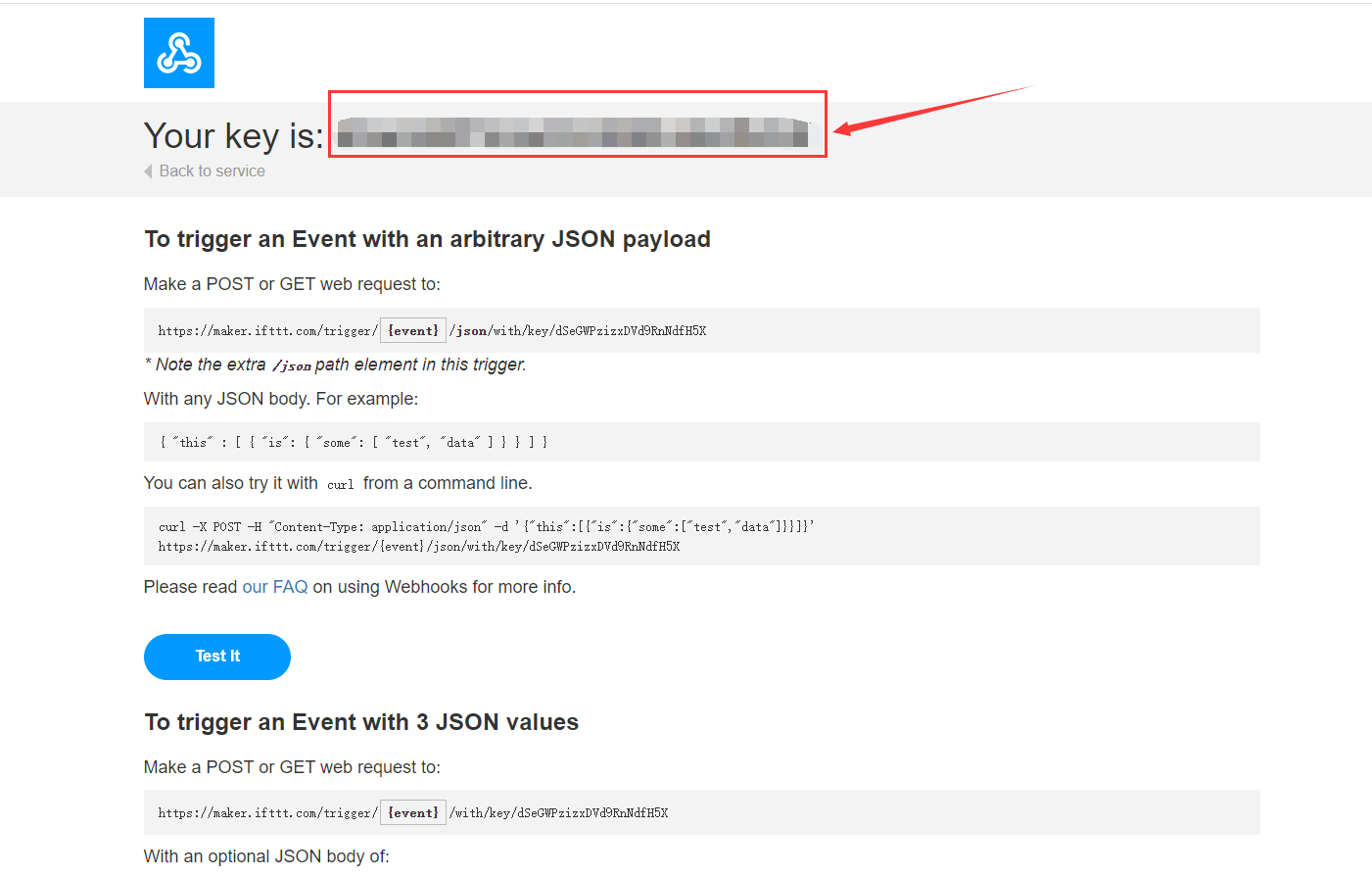
-
10.6.2.2 示例程序
-
烧录Arduino程序
-
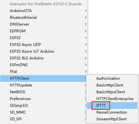
打开内置的例程
-
程序功能:如果收到”message“,FireBeetle 2 ESP32-E将会给设置的邮箱发邮件。
#include <WiFi.h> #include <HTTPClient.h> //配置WiFi名称和密码 char *WIFI_SSID = "WIFI_SSID"; char *WIFI_PASSWORD = "WIFI_PASSWORD"; //配置IFTTT char *IFTTT_ENVENT = "Your_Event"; char *IFTTT_KEY = "Your_Key"; //IFTTT发送消息 char *IFTTT_VALUE_1 = "Value1"; char *IFTTT_VALUE_2 = "Value2"; char *IFTTT_VALUE_3 = "Value3"; HTTPClient ifttt; unsigned long lastTime = 0; unsigned long timerDelay = 10000; void setup() { Serial.begin(115200); WiFi.begin(WIFI_SSID, WIFI_PASSWORD); Serial.println("Connecting"); while(WiFi.status() != WL_CONNECTED) { delay(500); Serial.print("."); } Serial.println(""); Serial.print("Wifi Connect Success"); } void loop() { //每10秒发送一次HTTP POST请求 if ((millis() - lastTime) > timerDelay) { //检查WIFI连接状态 if(WiFi.status()== WL_CONNECTED){ ifttt.IFTTTBeging(IFTTT_ENVENT,IFTTT_KEY); int dataSendState = ifttt.IFTTTSend(IFTTT_VALUE_1,IFTTT_VALUE_2,IFTTT_VALUE_3); Serial.println(dataSendState);//打印数据是否发送成功 }else { Serial.println("WiFi Disconnected"); } lastTime = millis(); } } -
配置Arduino程序中的参数
//配置WiFi名称和密码
char *WIFI_SSID           = "WIFI_SSID";//输入WiFi名称
char *WIFI_PASSWORD       = "WIFI_PASSWORD";//输入WiFi密码
//配置IFTTT
char *IFTTT_ENVENT        = "Your_Event";//输入事件名称
char *IFTTT_KEY           = "Your_Key";//输入IFTTT中找到的Key
//IFTTT发送消息
char *IFTTT_VALUE_1       = "Value1";
char *IFTTT_VALUE_2       = "Value2";
char *IFTTT_VALUE_3       = "Value3";//配置在邮件信息中的三个值
-
10.6.2.3 程序执行结果
在邮箱中收到由FireBeetle 2 ESP32-E发出的数据
FAQ
- SD库的使用中,烧录程序后,串口不显示打印内容或者显示连接失败,可以尝试按下RST键。
驱动安装
FireBeetle 2 ESP32-E采用CH340串口芯片,在绝大部分的设备中,都可以免驱使用。若您发现插上设备,驱动没有自动安装,也可以自行手动安装:
Windows驱动安装——点击下载CH340驱动程序
Mac驱动安装——点击下载CH340驱动程序

资料下载
更多
更多问题及有趣的应用,可以 访问论坛 进行查阅或发帖。
