概述
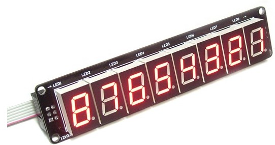
SPI LED Module 是一个8位LED显示模块,基于静态扫描原理,使用SPI接口自动移位显示。优点LED不闪烁、程序简单、占用Arduino IO口少。配合Arduino interface shield使用,可级联成多个LED显示。你可以使用这个套件完成一个简单的定时、计数器或者时钟模块,在其他互动媒体系统中它也可以作为一个显示模块。可以配合Shiftout LED模块一起使用。
技术规格
- 模块工作电压:5V
- 通讯接口:SPI
- 数码管颜色:红色
- 显示方式:静态扫描
- 可级联数量:2个以上
- 数码管位数:8个
- 可直插接入Interface Shield使用
- 连接Interface Shield后所占用的引脚:D3,D8,D9
- 组合尺寸:122x20x12mm
连线图
该模块与接口屏蔽通过IDC6电缆。确保先输入到“输入”插座模块插入。第二个模块“输入插座”,“输出”插座相连。
引脚图

示例代码
//Pin connected to latch pin (ST_CP) of 74HC595
const int latchPin = 8;
//Pin connected to clock pin (SH_CP) of 74HC595
const int clockPin = 3;
////Pin connected to Data in (DS) of 74HC595
const int dataPin = 9;
byte Tab[]={0xc0,0xf9,0xa4,0xb0,0x99,0x92,0x82,0xf8,0x80,0x90,0xff};
void setup() {
  //set pins to output because they are addressed in the main loop
  pinMode(latchPin, OUTPUT);
  pinMode(dataPin, OUTPUT);
  pinMode(clockPin, OUTPUT);
  Serial.begin(9600);
  Serial.println("reset");
}
void loop() {
  if (Serial.available() > 0) {
    // ASCII '0' through '9' characters are
    // represented by the values 48 through 57.
    // so if the user types a number from 0 through 9 in ASCII,
    // you can subtract 48 to get the actual value:
  int bitToSet = Serial.read() - 48;
  // write to the shift register with the correct bit set high:
  digitalWrite(latchPin, LOW);
  // shift the bits out:
  shiftOut(dataPin, clockPin, MSBFIRST, Tab[bitToSet]);
    // turn on the output so the LEDs can light up:
  digitalWrite(latchPin, HIGH);
  }
}
测试程序
- 上传草图。
- 链接“输入”插座,LED模组接口屏蔽的“shiftout”插座
- 打开串口监视器,然后键入“12345678”。 LED模块应显示“87654321”
 购买
购买