简介
数字电位器Digital Potentiometer(简称Digital Pot)是一种可以通过Arduino等微控制器编程控制,动态地改变阻值的CMOS模数混合集成电路。与传统机械式电位器相比,数字电位器具有使用灵活(编程控制)、体积小(芯片)、可靠性高(没有机械部件)等显著优点,可在多种应用场景代替传统机械电位器。数字电位器常用于音频播放设备的程控音量调节中,如智能音箱、手机、音乐播放器中的音量调节。此外,如果配合运算放大器,数字电位器还可以用于动态改变电路的主要参数,如:LED直流调光(输出电流)、线性稳压电源(输出电压)、振荡器(频率和振幅)、低通滤波器(带宽)和差分放大器(增益)等应用场景中。
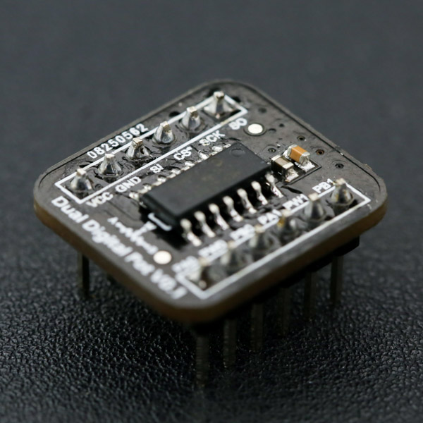
本模块使用MCP42100 100K双路数字电位器,宽供电电压(DC 2.7V-5.5V),兼容目前绝大部分微控制器的3.3V或5V供电,带有两路可独立工作的数字电位器POT0和POT1,256级电阻抽头。该模块体积小(20.0mm*18.0mm),预留SO引脚(串行数据输出),可将多个模块级联使用。配合I/O扩展板与所附送的5P多对一公对公杜邦线,可方便地与Arduino进行快速连接。
技术规格
- 工作电压:2.7~5.5V DC
- 静态工作电流:< 1 μA
- 端到端电阻:100 KΩ
- 分辨率:8位,256个电阻抽头
- 电位器数量:2个
- 接口类型:SPI
- 工作温度:-40℃~85℃
- 尺寸:20.0mm*18.0mm
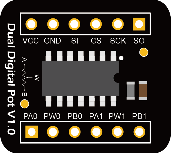
引脚说明
| 管脚名 | 功能描述 |
|---|---|
| VCC | 电源 (DC 2.7V - 5.5V) |
| GND | 地 (电源负极) |
| SI | 串行数据输入 |
| CS | 片选 |
| SCK | 串行时钟 |
| SO | 串行数据输出 |
| PAx | 电位器A引脚(x=0,1) |
| PBx | 电位器B引脚(x=0,1) |
| PWx | 电位器W抽头引脚(x=0,1) |
⚠注意:
- 引脚A、B和W与机械电位器一样,无极性之分
- 流经引脚A、B和W的电流不能超过±1mA
- 施加在引脚A、B和W上的电压应在0 - VCC之间
教程
该示例利用模块的两路数字电位器产生两组相位相反的三角波以演示模块的基本使用与控制。这里将模块的两个电位器POT0和POT1作为分压器(A端接5V,B端接GND),将POT0的中间抽头W0每隔1ms从最小调节到最大(0->255),然后再调节到最小(255->0)。与之相反,将POT1的中间抽头W1每隔1ms从最大调节到最小(255->0),然后再调节到最大(0->255),用示波器两路通道CH1和CH2分别观察W0和W1对地电压波形,以检验电位器是否可以切换到所有可能的电阻值。
基础知识
- 本模块所采用的MCP42100集成了两路数字电位器POT0和POT1分别对应两组引脚A0、B0、W0和A1、B1、W1。与机械电位器类似,A、B两端可看作一电阻的两端,标称电阻Rab=100K,W端作为中间抽头,可以在A、B两端当中256个均匀分布的位置上变化,实现阻值的变化。模块上电时,两路数字电位器的W端均在中间位置。

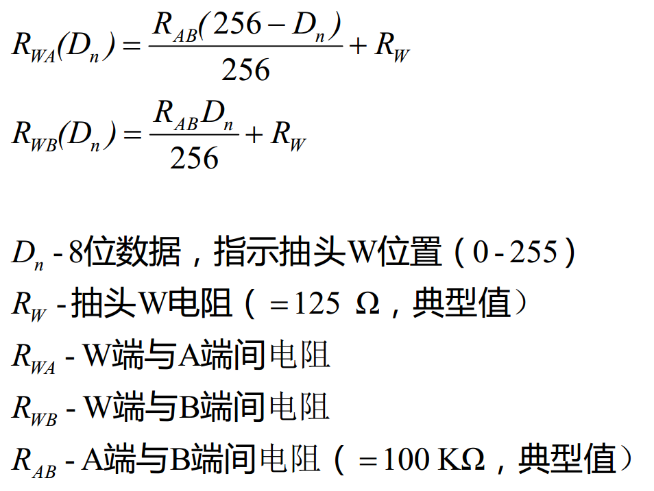
- 要改变数字电位器W端的位置需要通过SPI向模块发送两个字节,第一个字节作为指令Command,选中其中一个数字电位器或同时指定两个电位器,第二个字节作为数据Data,指定中间抽头W的位置值Dn(8位,0-255),Dn=0时,B端与W端相连,Dn=255时,W端最靠近A端(但不相连,还差一个Rab/256+Rw,其中Rw为芯片内部W端的抽头电阻,典型值为125Ω)。例如,将第一个数字电位器W端设置到100的位置,需要先发送0x11,再发送0x64(=100,十进制)即可。


- 数字电位器的各部分阻值可通过下面的公式计算。
准备
-
硬件
- Ardruino UNO R3主控板 x1
- I/O 传感器扩展板 V7.1(可选) x1
- 面包板 x1
- 杜邦连接线 x1
-
软件
- Arduino IDE (1.8.x), 点击下载Arduino IDE
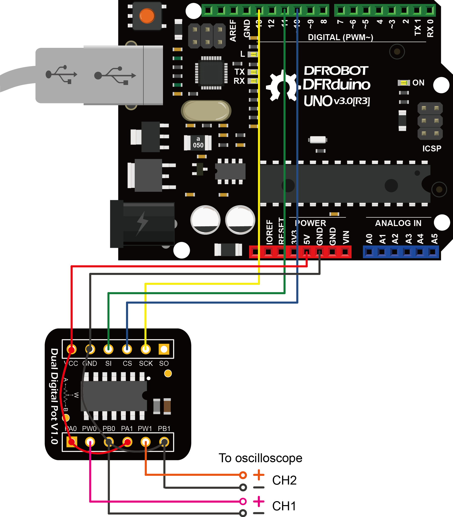
硬件连接
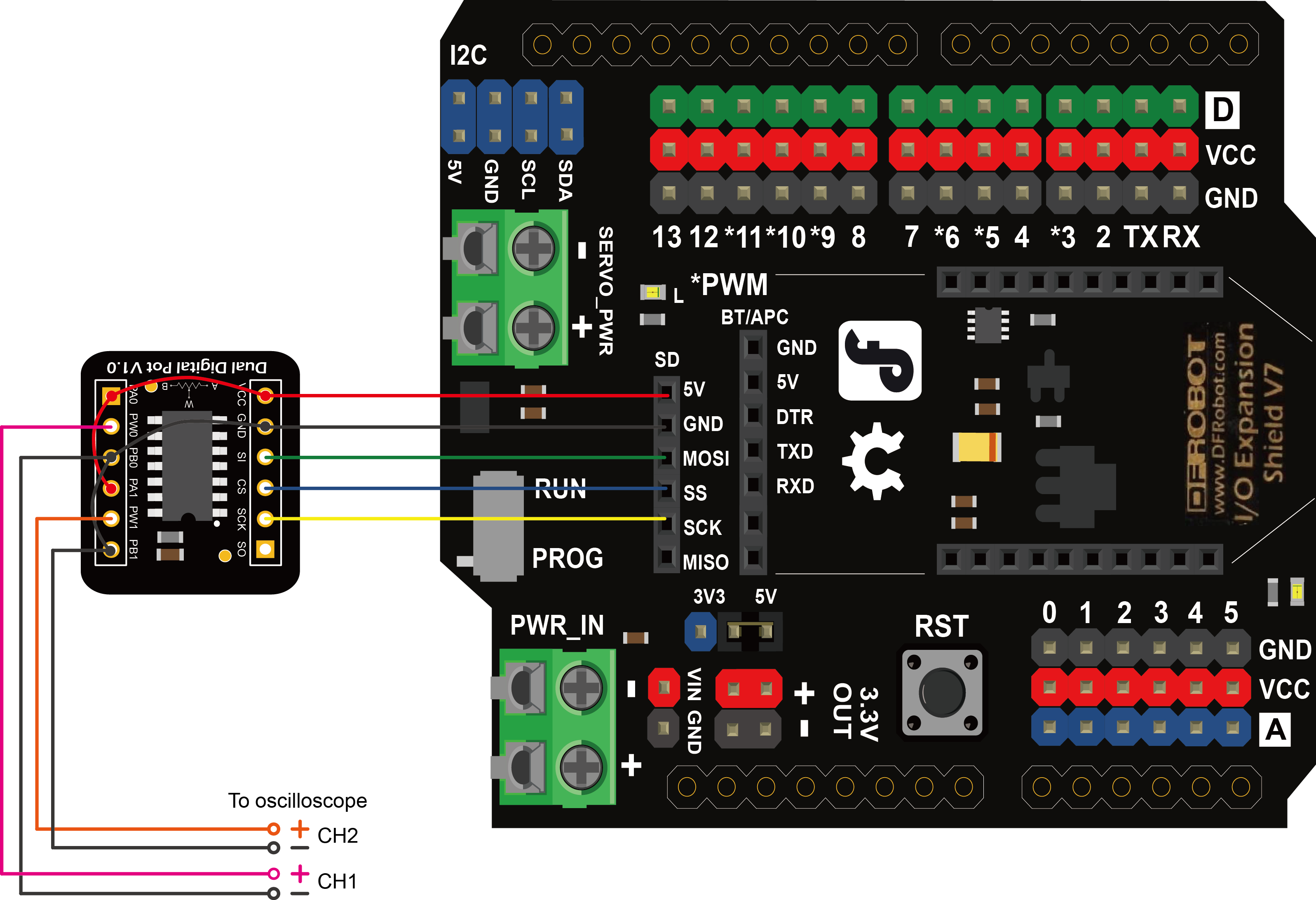
- 模块可使用附带的5Pin杜邦公对公排线(一端连体另外一端单独分开)连接。首先将模块插入面包板,将连体一头直接插入模块标有VCC和GND所在一排的引脚中(此时SO应留空),另一头非连体部分可分别如下图插入Arduino主控板上。若使用I/O扩展板,则可捋顺非连体部分的杜邦头,对齐直接插入扩展板SD卡的SPI接口上(除MISO不接),较为方便地实现连接。
样例代码
- 若使用I/O扩展板上SD卡的SPI接口,需要将程序中的“const int CS_PIN = 10;”,改为“const int CS_PIN = 4;”,因为该SPI接口的SS与D4相连。
/*************************************************************
        Dual Digital Pot(100K)
     *************************************************************
       This example generates two triangular waves to demo the usage of
       dual digital pot.

       Created 2017-8-31
       By Henry Zhao <Henry.zhao@dfrobot.com>

       GNU Lesser Genral Public License.
       See <https://www.gnu.org/licenses/> for details.
       All above must be included in any redistribution.
     ************************************************************/

/***********************Circuit Connections*******************
      Digital Pot  |   Arduino UNO R3    |   Oscilloscope
          CS       |     D10 (SS)        |
          SI       |     D11 (MOSI)      |
          CLK      |     D13 (SCK)       |
      VCC,PA0,PA1  |       VCC           |
      GND,PB0,PB1  |       GND           |     CH1- CH2-
          W0       |                     |       CH1+
          W1       |                     |       CH2+
 ************************************************************/

/***********************Notice********************************
   1.Resistor terminals Ax,Bx and Wx have no restrictions on
     polarity with respect to each other.
   2.Current through terminals A, B and W should not excceed ±1mA.
   3.Voltages on terminals A, B and W should be within 0 - VCC.
************************************************************/

#include <SPI.h>

/***********************PIN Definitions*************************/
// set pin 4 as the slave select (SS) for the digital pot:
// for using the SD SPI interface of Gravity IO Expansion Shield for Arduino V7.1
//const int CS_PIN = 4;

// set pin 10 as the slave select (SS) for the digital pot
// for using Arduino UNO
const int CS_PIN = 10;

/***********************MCP42XXX Commands************************/
//potentiometer select byte
const int POT0_SEL = 0x11;
const int POT1_SEL = 0x12;
const int BOTH_POT_SEL = 0x13;

//shutdown the device to put it into power-saving mode.
//In this mode, terminal A is open-circuited and the B and W terminals are shorted together.
//send new command and value to exit shutdowm mode.
const int POT0_SHUTDOWN = 0x21;
const int POT1_SHUTDOWN = 0x22;
const int BOTH_POT_SHUTDOWN = 0x23;

/***********************Customized Varialbes**********************/
//resistance value byte (0 - 255)
//The wiper is reset to the mid-scale position upon power-up, i.e. POT0_Dn = POT1_Dn = 128
int POT0_Dn = 128;
int POT1_Dn = 128;
int BOTH_POT_Dn = 128;

//Function Declaration
void DigitalPotTransfer(int cmd, int value);     //send the command and the wiper value through SPI

void setup()
{
  Serial.begin(115200);
  pinMode(CS_PIN, OUTPUT);   // set the CS_PIN as an output:
  SPI.begin();     // initialize SPI:
}

void loop()
{
  // change the resistance on the POT0 from min to max:
  for (int POT_Dn = 0; POT_Dn < 256; POT_Dn++) {
    DigitalPotWrite(POT0_SEL, POT_Dn);
    delay(1);
  }

  // change the resistance on the POT0 from max to min:
  for (int POT_Dn = 0; POT_Dn < 256; POT_Dn++) {
    DigitalPotWrite(POT0_SEL , 255 - POT_Dn);
    delay(1);
  }
}

void DigitalPotWrite(int cmd, int val)
{
  // constrain input value within 0 - 255
  val = constrain(val, 0, 255);
  // set the CS pin to low to select the chip:
  digitalWrite(CS_PIN, LOW);
  // send the command and value via SPI:
  SPI.transfer(cmd);
  SPI.transfer(val);
  // Set the CS pin high to execute the command:
  digitalWrite(CS_PIN, HIGH);
}
实验结果
从示波器可观察到两组相位相反的三角波信号。若将该信号放大观察,可发现该三角波由很多阶梯组成,每级阶梯对应一个抽头电阻W的位置,其宽度正好对应每次改变电位器的延时1ms,三角波上升半周期和下降半周期分别由256级阶梯组成,因此整个三角波的周期为256*2=512ms。由此可见,两路数字电位器可快速切换抽头位置,稳定时间达到微秒级别

MCP42100基本控制模板代码
- 用户可以通过修改下面所提供的模板代码,方便地改变数字电位器的阻值,实现对其的各种控制。
实验代码
/*************************************************************
        Dual Digital Pot (100K)
     *************************************************************
       This example serves as a template to control the MCP42100 dual
       digital pot through 3-wire SPI.

       Created 2017-8-31
       By Henry Zhao <Henry.zhao@dfrobot.com>

       GNU Lesser Genral Public License.
       See <https://www.gnu.org/licenses/> for details.
       All above must be included in any redistribution.
     ************************************************************/

/********************Device Inctrduction**********************
   The MCP42100 has dual potentiometer x (x=0,1).
     Ax - Potenriometer terminal Ax
     Wx - Potenriometer Wiper
     Bx - Potenriometer terminal Bx

     SI - Serial Data Input
     SCK - Serial Clock
     CS - Chip Select

     The MCP42100 is SPI-compatible,and two bytes should be sent to control it.
     The first byte specifies the potentiometer (POT0: 0x11, POT1: 0x12, both: 0x13).
     The second byte specifies resistance value for the pot (0 - 255).
 ************************************************************/

/***********************Circuit Connections*******************
     Digital Pot | Arduino UNO R3
         CS      |    D10 (SS)
         SI      |    D11 (MOSI)
         CLK     |    D13 (SCK)
         VCC     |      VCC
         GND     |      GND
 ************************************************************/

/***********************Resistances Calculation**************
   Rwa(Dn) =Rab*(256 - Dn) / 256 + Rw
   Rwb(Dn) =Rab*Dn / 256 + Rw

   Rwa - resistance between Terminal A and wiper W
   Rwb - resistance between Terminal B and wiper W
   Rab - overall resistance for the pot (=100KΩ ±30%)
   Rw - wiper resistance (=125Ω,typical; =175Ω max)
   Dn - 8-bit value in data register for pot number n (= 0 - 255)
 ************************************************************/

/***********************Notice********************************
   1.Resistor terminals Ax,Bx and Wx have no restrictions on
     polarity with respect to each other.
   2.Current through terminals A, B and W should not excceed ±1mA.
   3.Voltages on terminals A, B and W should be within 0 - VCC.
************************************************************/

#include <SPI.h>

/***********************PIN Definitions*************************/
// set pin 4 as the slave select (SS) for the digital pot:
// for using the SD SPI interface of Gravity IO Expansion Shield for Arduino V7.1
//const int CS_PIN = 4;

// set pin 10 as the slave select (SS) for the digital pot
// for using Arduino UNO
const int CS_PIN = 10;

/***********************MCP42XXX Commands************************/
//potentiometer select byte
const int POT0_SEL = 0x11;
const int POT1_SEL = 0x12;
const int BOTH_POT_SEL = 0x13;

//shutdown the device to put it into power-saving mode.
//In this mode, terminal A is open-circuited and the B and W terminals are shorted together.
//send new command and value to exit shutdowm mode.
const int POT0_SHUTDOWN = 0x21;
const int POT1_SHUTDOWN = 0x22;
const int BOTH_POT_SHUTDOWN = 0x23;

/***********************Customized Varialbes**********************/
//resistance value byte (0 - 255)
//The wiper is reset to the mid-scale position upon power-up, i.e. POT0_Dn = POT1_Dn = 128
int POT0_Dn = 128;
int POT1_Dn = 128;
int BOTH_POT_Dn = 128;

//Function Declaration
void DigitalPotTransfer(int cmd, int value);     //send the command and the resistance value through SPI

void setup()
{
  pinMode(CS_PIN, OUTPUT);    // set the CS_PIN as an output:
  SPI.begin();     // initialize SPI:
  DigitalPotWrite(BOTH_POT_SHUTDOWN, BOTH_POT_Dn);
}

void loop()
{

  DigitalPotWrite(POT0_SEL, POT0_Dn);                 //set the resistance of POT0
  DigitalPotWrite(POT1_SEL, POT1_Dn);                 //set the resistance of POT1
  //DigitalPotWrite(BOTH_POT_SEL, BOTH_POT_Dn);         //set the resistance of both potentiometers

  //DigitalPotWrite(POT0_SHUTDOWN, POT0_Dn);              //put POT0 into shuntdowm mode, ignore the second parameter
  //DigitalPotWrite(POT1_SHUTDOWN, POT1_Dn);              //put POT1 into shuntdowm mode, ignore the second parameter
  //DigitalPotWrite(BOTH_POT_SHUTDOWN, BOTH_POT_Dn);      //put both potentiometers into shuntdowm mode, ignore the second parameter

}

void DigitalPotWrite(int cmd, int val)
{
  // constrain input value within 0 - 255
  val = constrain(val, 0, 255);
  // set the CS pin to low to select the chip:
  digitalWrite(CS_PIN, LOW);
  // send the command and value via SPI:
  SPI.transfer(cmd);
  SPI.transfer(val);
  // Set the CS pin high to execute the command:
  digitalWrite(CS_PIN, HIGH);
}
常见问题
还没有客户对此产品有任何问题,欢迎通过qq或者论坛联系我们!
更多问题及有趣的应用,可以 访问论坛 进行查阅或发帖。
