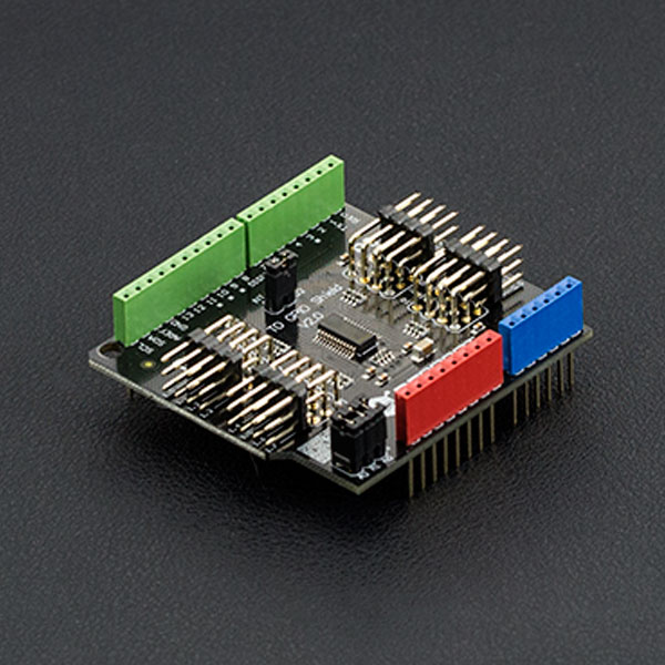
概述
在使用Arduino做机器人或互动媒体时,有没有发现数字IO口不够用?现在I2C转I/O模块帮你解决问题,Arduino 只需要2根数据线(SCL-Analog PIN5,SDA-Analog PIN4)即可和I2C转I/O模块通讯,将转换出16路数字IO口,可读可写。可同时并联8个模块,每个模块可以设置不同I2C地址,以便您根据项目的数字口需要串联多个模块进行数据采集和控制。
注意:V1.0本版本将不再销售,请查看V2.0版本维库页面
技术规格
- 模块电源:+5V
- 扩展16个数字IO口自带内部上拉
- 可设置8个地址(地址范围0x20~0x27)
- 可同时并联8个模块(I2C总线需加上拉)
- 模块尺寸:42x40mm
示例代码
/******************************************************************************
Test Program for the 12C PCA9555 Board part number DFR0013 I2C TO GPIO module from dfrobot.com
16 outputs that I used to drive this relay board made in Bulgaria
http://www.denkovi.com/product/21/16-relay-board-for-your-pic-avr-project-12v.html
it's a great little expansion board that can be used to drive LEDs or anything you want.
made by peter@testelectronics.com
January 07th 2011
My biggest problem was figuring out the I2C address of the PCA9555.
If there are no jumpers the address is 1 0 0 '1 1 1'
Jumpers make the address 1 0 0 '0 0 0'. This is opposite of what I expected.
******************************************************************************/

#include <Wire.h>

//  with no jumpers the full address is   1 0 0 1 1 1    1 0 0 A2 A1 A0  0x27 is the default address for the DFR0013 board with no jumpers.
#define PCA9555 0x27 // 0x27 is default address for the DFR0013 board with no jumpers.
                     // 0x20 is address for the DFR0013 board with all jumpers.
// COMMAND BYTE TO REGISTER RELATIONSHIP FROM PCA9555 DATA SHEET
// At reset, the device's ports are inputs with a high value resistor pull-ups to VDD
// If relays turning on during power up are a problem. Add a pull down resistor to each relay transistor base.

#define IN_P0 0x00 // Read Input port0
#define IN_P1 0x01 // Read Input port1
#define OUT_P0 0x02 // Write Output port0
#define OUT_P1 0x03 // Write Output port1
#define INV_P0 0x04 // Input Port Polarity Inversion port0 if B11111111 is written input polarity is inverted
#define INV_P1 0x05 // Input Port Polarity Inversion port1 if B11111111 is written input polarity is inverted
#define CONFIG_P0 0x06 // Configuration port0 configures the direction of the I/O pins 0 is output 1 is input
#define CONFIG_P1 0x07 // Configuration port1 configures the direction of the I/O pins 0 is output 1 is input

#define PAUSE 200

void setup()
{
  Wire.begin(PCA9555); // join i2c bus (address optional for master) tried to get working
  write_io (CONFIG_P0, B00000000); //defines all pins on Port0 are outputs
  write_io (CONFIG_P1, B00000000); //defines all pins on Port1 are outputs
  write_io (OUT_P0, B00000000); //clears all relays
  write_io (OUT_P1, B00000000); //clears all relays
  delay (PAUSE);
}


void loop()
{
  write_io (OUT_P0, B00000001);
  delay (PAUSE);
  write_io (OUT_P0, B00000010);
  delay (PAUSE);
  write_io (OUT_P0, B00000100);
  delay (PAUSE);
  write_io (OUT_P0, B00001000);
  delay (PAUSE);
  write_io (OUT_P0, B00010000);
  delay (PAUSE);
  write_io (OUT_P0, B00100000);
  delay (PAUSE);
  write_io (OUT_P0, B01000000);
  delay (PAUSE);
  write_io (OUT_P0, B10000000);
  delay (PAUSE);
  write_io (OUT_P0, B00000000);


  write_io (OUT_P1, B00000001);
  delay (PAUSE);
  write_io (OUT_P1, B00000010);
  delay (PAUSE);
  write_io (OUT_P1, B00000100);
  delay (PAUSE);
  write_io (OUT_P1, B00001000);
  delay (PAUSE);
  write_io (OUT_P1, B00010000);
  delay (PAUSE);
  write_io (OUT_P1, B00100000);
  delay (PAUSE);
  write_io (OUT_P1, B01000000);
  delay (PAUSE);
  write_io (OUT_P1, B10000000);
  delay (PAUSE);
  write_io (OUT_P1, B00000000);

}


 void write_io(int command, int value)
{
  Wire.beginTransmission(PCA9555);
  Wire.send(command),Wire.send(value);
  Wire.endTransmission();
}
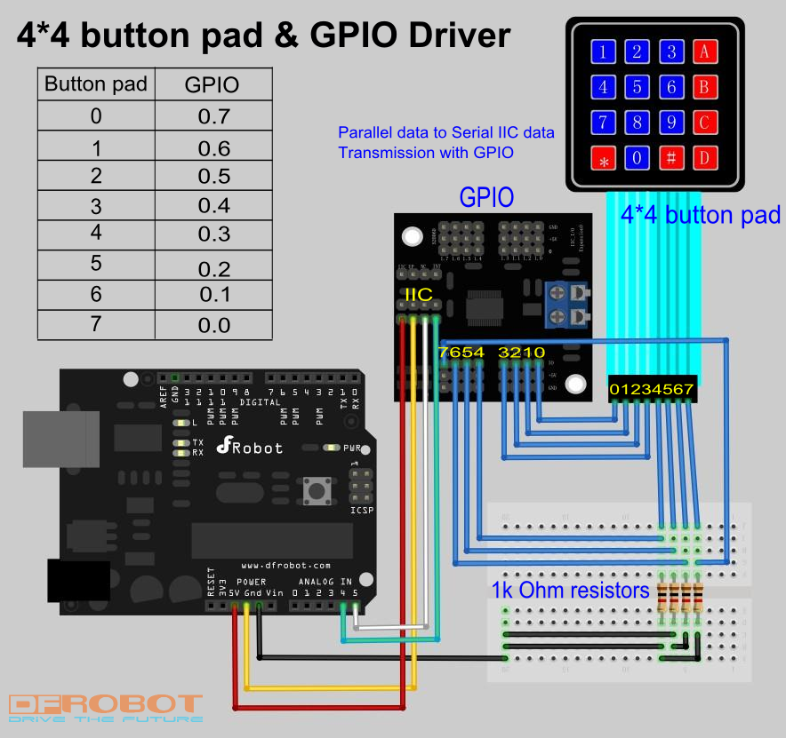
连线示意图
示例代码
    /*
    Hardware preparation: a 4*4 button pad, a GPIO, 4 1k Ohm resistors.
    sample code for Sealed membrane 4*4 button pad with sticker, it outputs the ASCII code for keys on the pad.
    In this sample, to save the I/O port on Arduino board, we use a I2C-GPIO modulo (SKU:DFR0013). It transform the
    I2C port on the Arduino board into GPIO I/O port.For more details, please turn to this page:

    http://www.dfrobot.com/wiki/index.php?title=Arduino_I2C_to_GPIO_Module_(SKU:DFR0013)#Discussion


    The general working principle of this key pad is a 4*4 matrix. The sample code scans the 4*4 matrix in a short time
    and determines whether there is a signal input( pression on the keypad).
    Before reading this sample code, you'd better have a look at the sample connection pic. You may wonder why there are
    four resistors. This is because that if there are no such resistors, the data analogRead() gets will be a stochastic value
    between 0-1023. It will be impossible to determine whether the connection is made by pressing the button on the key pad.
    */

    /*

    Support: Arduino 1.0 or lower version
    Author: Sheng Kaiyu
    Editor: Michael
    from DFrobot, Shanghai, China
    Date: 2012/3/13
    */

    #include <Wire.h>


    #define PCA9555 0x20 // address for PCA9555
    #define OUT_P0 0x02 // Write Output port0
    #define CONFIG_P0 0x06 // Configuration port0 configures the direction of the I/O pins, 0 is output, 1 is input
    #define IN_P0 0x00 //Read Input port0

    #if defined(ARDUINO) && ARDUINO >= 100
    #define printIIC(args) Wire.write((uint8_t)args)
    #define readIIC() Wire.read()
    #else
    #define printIIC(args) Wire.send(args)
    #define readIIC() Wire.receive()
    #endif


    void setup()
    {
      Serial.begin(9600);
      Wire.begin(PCA9555); // join i2c bus (address optional for master) tried to get working
      write_io (CONFIG_P0, B00001111); //define port 0.7-0.4 as output, 0.3-0.0 as input
    }


    void loop()
    {
      unsigned char key;                                   // read and output once until the next pression
      key=readdata();
      if  (key!='E')
      {Serial.println(key);}
      delay(100);                                          // to avoid interruption
      while (readdata()==key)
      {}

    }


    unsigned char readdata(void)          //main read function
    {
      int input=128;                      //binary 10000000, set pin 0.7 HIGH
      for (int i=0;i<4;i++)               //for loop
      {
        write_io (OUT_P0, input);

        unsigned int temp=0x8;            //temporary integer, binary 1000, to compare with gpio_read() function and determine pression
        for (int j=0;j<4;j++)
          {
             if (gpio_read(PCA9555)==temp)
             { return outputchar(i,j);}   // output the char
             temp=temp>>1 ;               // shift right
          }
        input=input>>1;                   //shift right, set the next pin HIGH, set previous one LOW
      }
      return 'E';                         // if no button is pressed, return E
    }


     void write_io(int command, int value)  //write into register
    {
      Wire.beginTransmission(PCA9555);      //begin transmission
      printIIC(command);                  //which register
      printIIC(value);                    //write value
      Wire.endTransmission();               //end transmission
    }

    unsigned int gpio_read(int address)   //read from pin 0.3 ~ 0.0
    {
      int data = 0;
      Wire.beginTransmission(address);
      printIIC(IN_P0);                // warning: this may be a bug in Arduino 1.0. transform 0x00 (input register) into byte 0, otherwise this compiler will return error
      Wire.endTransmission();
      Wire.beginTransmission(address);
      Wire.requestFrom(address, 1);
      if (Wire.available())
      {
        data = readIIC( )&0x0F ;           // read lower 4 bit  0.3 ~ 0.0

      }
      Wire.endTransmission();
      return data;
    }


    unsigned char outputchar(int i, int j)   // output chars on the pad
    {
      if (i==0)
      { switch (j)
        {case 0:
               return '1'; break;
         case 1:
               return '2'; break;
         case 2:
               return '3'; break;
         case 3:
               return 'A'; break;
        }
      }
       if (i==1)
      { switch (j)
        {case 0:
               return '4'; break;
         case 1:
               return '5'; break;
         case 2:
               return '6'; break;
         case 3:
               return 'B'; break;
        }
      }
       if (i==2)
      { switch (j)
        {case 0:
               return '7'; break;
         case 1:
               return '8'; break;
         case 2:
               return '9'; break;
         case 3:
               return 'C'; break;
        }
      }
       if (i==3)
      { switch (j)
        {case 0:
               return '*'; break;
         case 1:
               return '0'; break;
         case 2:
               return '#'; break;
         case 3:
               return 'D'; break;
        }
      }
    }
 购买
购买