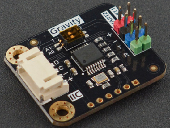
简介
Arduino、树莓派、micro:bit等主板往往只有1-2个UART串口,而且有一个串口会作为程序下载或调试用,如果项目中需要连接多个UART设备,主板将难以连接。对于Arduino主板,我们往往通过IO口虚拟串口,但是虚拟串口将会打乱其他程序的执行,例如时序有严格要求的红外接收模块、WS2818单总线RGB灯。而我们的I2C to dual UART module I2C转双串口模块很好地解决了这个问题,该模块将主板的I2C接口转换为两个串口,可以连接两个串口设备,如果不够,你还可以级联多个I2C转双串口模块。 I2C to dual UART module I2C最高速率为1Mbps,每个子串口具备收/发独立的256字节FIFO硬件缓存,串口的波特率,字长,校验格式可独立设置,最高提供2M bps的通信速率,支持4个I2C地址,一块主控上最多并联4个模块,一次最多扩展8个硬串口。
技术规格
- 工作电压:3.3~5V
- 工作电流:<3mA
- 通信接口:Gravity-I2C 4Pin
- I2C地址:传输协议规定,见使用教程
- 扩展串口数量:2个
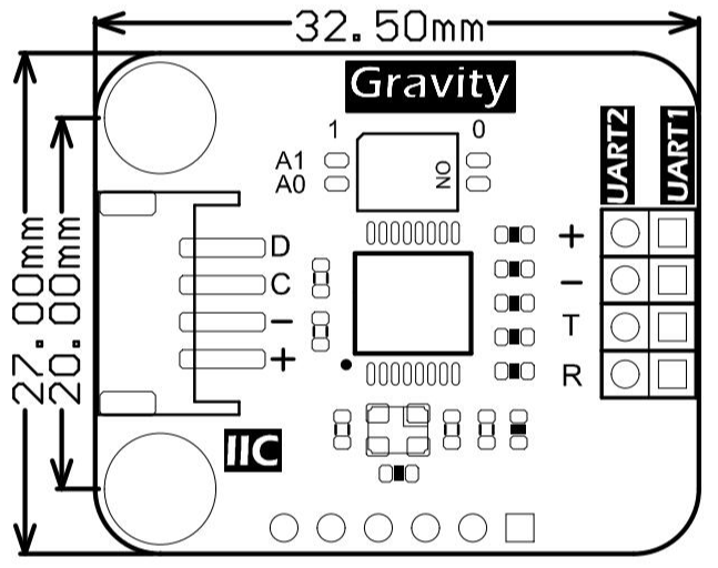
- 尺寸:32.5mmx27mm
- 安装孔尺寸:20mm
- 工作温度:-40℃~85℃
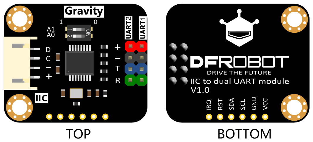
引脚说明
| 丝印 | 功能描述 |
|---|---|
| D | I2C数据SDA |
| C | I2C时钟SCL |
| - | 电源负极 |
| + | 电源正极 |
| T | 串口发送端 |
| R | 串口接受收端 |
拨码开关与地址的对应关系
I2C转双串口模块是一个非标准的I2C设备,它的地址不唯一。I2C地址有7位数据,运行I2C地址扫描程序时,只要高4位和模块的地址一样,就会应答,故在一个模块上,你会扫描出多个I2C地址,它们的高四位是一致的。模块地址配置如下表所示:
| 位 | 6 | 5 | 4 | 3 | 2 | 1 | 0 |
| 值 | IA1 | IA0 | 1 | 0 | C1 | C0 | 0/1 |
I2C转双串口
第6位:IA1的值对应I2C转双串口模块上拨码开关A1的值;
第5位:IA0的值对应I2C转双串口模块上拨码开关A0的值;
拨码开关与IA1和IA0的对应关系表
| 拨码开关A1 | 拨码开关A0 | IA1 | IA0 |
|---|---|---|---|
| 0 | 0 | 0 | 0 |
| 0 | 1 | 0 | 1 |
| 1 | 0 | 1 | 0 |
| 1 | 1 | 1 | 1 |
第4位:固定位,值为1;
第3位:固定位,值为0;
第2/1位:C1C0代表子串口通道号,如00代表UART1,01代表UART2;
第0位:代表操作的对象是模块的寄存器还是FIFO,0代表寄存器,1代表FIFO
Arduino使用教程
I2C转串口模块对象构
构造I2C转双串口对象时, 需要指定子串口号(UART1或UART2)以及IA1和IA0的值,构造函数如下所示:
DFRobot_IIC_Serial(TwoWire &wire = Wire, uint8_t subUartChannel = SUBUART_CHANNEL_1, uint8_t IA1 = 1, uint8_t IA0 = 1);
-
如果要操作UART1,则需传递参数SUBUART_CHANNEL_1,如果要操作UART2,则需传递参数SUBUART_CHANNEL_2;
-
如果模块的拨码开关状态为A1(1), A2(0), 需在形参IA1和IA0的位置分别传递参数1和0;
-
例:I2C转双串口模块的拨码开关A1拨至1,A0拨至0
-
- 构建对象,使用UART1,代码示例如下:
DFRobot_IIC_Serial iicSerial(Wire, SUBUART_CHANNEL_1, /*IA1=*/1, /*IA0=*/0);//构造对象UART1
-
- 构建对象,使用UART2,代码示例如下:
DFRobot_IIC_Serial iicSerial(Wire, SUBUART_CHANNEL_2, /*IA1=*/1, /*IA0=*/0);//构造对象UART2
设置波特率
I2C转双串口扩展出的UART同其他硬串口一样,也涉及到了波特率的设置,如将UART1的波特率设置为9600,UART2设置为115200, 示例代码如下所示:
iicSerial1.begin(9600); //UART1初始化,将波特率设置为9600
iicSerial2.begin(115200); //UART2初始化,将波特率设置为115200
I2C转双串口模块采用14.7456M晶振,它支持下表所示波特率:
| 序号 | 1 | 2 | 3 | 4 | 5 | 6 | 7 | 8 |
| 波特率 | 2400 | 4800 | 57600 | 7200 | 9600 | 14400 | 19200 | 28800 |
| 波特率 | 38400 | 76800 | 115200 | 153600 | 230400 | 460800 | 307200 | 921600 |
常见波特率支持表
用户可以将该模块配置为上表所示的波特率,也可以自定义波特率,比如设置为12800等。

注:由于波特率与晶振有关,晶振不能支持所有的波特率,故用户自定义波特率需要用户自己测试,是否可行。
准备
-
硬件
- 1 x Arduino UNO控制板
- 1 x I2C to dual UART module
-
软件
- Arduino IDE, 点击下载Arduino IDE
- 库和示例
关于如何安装库文件,点击链接
接线图
注:在运行下例代码前,需检查模块的拨码开关是否都拨到“1”位置,如果不是需要将其拨至“1”位置,或在下例demo的构造函数中修改形参IA1和IA0位置处传入的值
样例代码1
写一个例程,要求实现UART1和UART2的自收自发功能。将UART1的T引脚和R引脚通过杜邦线连接,再将UART2的TX和RX相连,UART1发送"hello,Serial1",UART2发送"123",分别接收各自发出的数据,并打印。
    /*!
     * @file dataTxAndRx.ino
     * @brief Receive and transmit data via UART. Read the data sent by TX pin via pin RX.
     * @n Experiment phenomenon: connect the TX to RX in Sub UART1 and UART2. Read the data sent by Sub UART and print it out.
     *
     * @copyright   Copyright (c) 2010 DFRobot Co.Ltd (https://www.dfrobot.com)
     * @licence     The MIT License (MIT)
     * @author [Arya](xue.peng@dfrobot.com)
     * @version  V1.0
     * @date  2019-07-28
     * @get from https://www.dfrobot.com
     * @url https://github.com/DFRobot/DFRobot_IIC_Serial
     */
    #include <DFRobot_IIC_Serial.h>
    /*DFRobot_IIC_Serial Constructor
     *Parameter&wire  Wire
     *Parameter subUartChannel sub UART channel, for selecting to operate UART1 or UART2
     *@n Available parameter:
         SUBUART_CHANNEL_1  SUBUART_CHANNEL_2
               UART1             UART2
     *Parameter IA1 corresponds with IA1 Level(0 or 1) of DIP switch on the module, and is used for configuring
     * @n the I2C address of the 6th bit value(default: 1).
     *Parameter IA0 corresponds with IA0 Level(0 or 1) of DIP switch on the module, and is used for configuring
     * @n I2C address of the 5th bit value(default: 1).
     * I2C address configuration:
     * 7   6   5   4   3   2   1   0
     * 0  IA1 IA0  1   0  C1  C0  0/1
     *@n I2C address only has 7 bits, while there are 8 bits for one byte, so the extra one bit will be filled as 0.
     *@n The 6th bit corresponds with IA1 Level of DIP switch, can be configured manually.
     *@n The 5th bit corresponds with IA0 Level of DIP switch, can be configured manually.
     *@n The 4th and 3rd bits are fixed, value 1 and 0 respectively
     *@n The values of the 2nd and 1st bits are the sub UART channels, 00 for sub UART 1, 01 for sub UART 2.
     *@n The 0 bit represents the operation object: 0 for register, 1 for FIFO cache.
     */
    DFRobot_IIC_Serial iicSerial1(Wire, /*subUartChannel =*/SUBUART_CHANNEL_1,/*IA1 = */1,/*IA0 = */1);//Construct UART1
    //DFRobot_IIC_Serial iicSerial1;//Default constructor, UART1, IA1 = 1, IA0 = 1
    DFRobot_IIC_Serial iicSerial2(Wire, /*subUartChannel =*/SUBUART_CHANNEL_2, /*IA1 = */1,/*IA0 = */1);//Construct UART2

    uint8_t flag = 0;//A flag bit, judge whether to print the prompt information of UART1 and UART2.
    //if it is 0, print "UART1 receive data: " or "UART2 receive data: "
    void setup() {
      Serial.begin(115200);
      /*begin Init function, set band rate according to the selected crystal frequency.
      begin(long unsigned baud) Call the function, set sub UART band rate.
      default setting->Band rate: baud, data format:IIC_SERIAL_8N1, 8 bits data, no check mode, 1 bit stop bit.
      begin(long unsigned baud, uint8_t format)Use the function to set band rate and data format:
      Parameter supported baud:2400, 4800, 57600, 7200, 9600, 14400, 19200, 28800, 38400,
                    76800, 115200, 153600, 230400, 460800, 307200, 921600
      Parameter available format:
      IIC_SERIAL_8N1  IIC_SERIAL_8N2  IIC_SERIAL_8Z1  IIC_SERIAL_8Z2  IIC_SERIAL_8O1
      IIC_SERIAL_8O2  IIC_SERIAL_8E1  IIC_SERIAL_8E2  IIC_SERIAL_8F1  IIC_SERIAL_8F2
      8 represents the number of data bit, N for no parity, Z for 0 parity, O for Odd parity, E for Even parity,
      F for 1 parity, 1 or 2 for the number of stop bit. Default IIC_SERIAL_8N1
      */
      iicSerial1.begin(/*baud = */115200);/*UART1 init*/
      //iicSerial1.begin(/*baud = */115200, /*format = */IIC_SERIAL_8N1);

      iicSerial2.begin(/*baud = */115200);/*UART2 init*/
      Serial.println("\n+--------------------------------------------+");
      Serial.println("|  Connected UART1's TX pin to RX pin.       |");//Connect pin TX and RX of UART1
      Serial.println("|  Connected UART2's TX pin to RX pin.       |");//Connect pin TX and RX of UART2
      Serial.println("|  UART1 send a String: \"hello, Serial1!\"    |");//UART1 transmit a string "hello, Serial1!"
      Serial.println("|  UART2 send a number: 123                  |");//UART2 transmit numbers 123
      Serial.println("+--------------------------------------------+");
      iicSerial1.println("hello, Serial1!");//UART1 transmit string:"hello, Serial1!"
      iicSerial2.write(123);//UART2 transmit:123
      Serial.println("Serial to print UART1 and UART2's receive data.");//print the data received by UART1 and UART2
    }

    void loop() {
      char c;
      if(iicSerial1.available()){/*available return the number of byte in UART1 receive buffer, none- return 0*/
        flag = 0;
        while(iicSerial1.available()){
          if(flag == 0){
            Serial.print("\nUART1 receive data: ");
            flag = 1;
          }
          c = iicSerial1.read();/*Read data of UART1 receive buffer */
          Serial.print(c);
        }
      }
      if(iicSerial2.available()){
        flag = 0;
        while(iicSerial2.available()){
          if(flag == 0){
            Serial.print("\nUART2 receive data: ");
            flag = 1;
          }
          Serial.print(iicSerial2.read());/*Read and print the data of Sub UART2 receive buffer*/
        }
      }
      delay(1000);
    }
结果
程序运行后,串口打印如下图所示:

样例代码2
通过UART2发送1个字符串"ABCDEFASFGHJUAAAEEB",接收并解析改字符串,要求将去掉该字符串中的字符"A",并将解析后的数据打印出来,示例代码如下所示:
/*!
 * @file cmdAnalysis.ino
 * @brief Analyze UART command, save and print (example: UART2, connect UART2's RX and TX together)
 * @n Transmit a random string via UART: "ABCDEFASFGHJUAAAEEB"
 * @n Receive the string, remove the char "A" of the string, and then print out the new string.
 *
 * @copyright   Copyright (c) 2010 DFRobot Co.Ltd (https://www.dfrobot.com)
 * @licence     The MIT License (MIT)
 * @author [Arya](xue.peng@dfrobot.com)
 * @version  V1.0
 * @date  2019-07-28
 * @get from https://www.dfrobot.com
 * @url https://github.com/DFRobot/DFRobot_IIC_Serial
 */
#include <DFRobot_IIC_Serial.h>
/*DFRobot_IIC_Serial Constructor
 *Parameter &wire  Wire
 *Parameter subUartChannel sub UART channel, for selecting to operate UART1 or UART2
 *@n Available parameter:
     SUBUART_CHANNEL_1  SUBUART_CHANNEL_2
           UART1             UART2
 *Parameter IA1 corresponds with IA1 Level(0 or 1) of DIP switch on the module, and is used for configuring
 * @n the I2C address of the 6th bit value(default: 1).
 *Parameter IA0 corresponds with IA0 Level(0 or 1) of DIP switch on the module, and is used for configuring
 * @n I2C address of the 5th bit value(default: 1).
 * I2C address configuration:
 * 7   6   5   4   3   2   1   0
 * 0  IA1 IA0  1   0  C1  C0  0/1
 *@n I2C address only has 7 bits, while there are 8 bits for one byte, so the extra one bit will be filled as 0.
 *@n The 6th bit corresponds with IA1 Level of DIP switch, can be configured manually.
 *@n The 5th bit corresponds with IA0 Level of DIP switch, can be configured manually.
 *@n The 4th and 3rd bits are fixed, value 1 and 0 respectively
 *@n The values of the 2nd and 1st bits are the sub UART channels, 00 for sub UART 1, 01 for sub UART 2.
 *@n The 0 bit represents the operation object: 0 for register, 1 for FIFO cache.
 */
DFRobot_IIC_Serial iicSerial2(Wire, /*subUartChannel =*/SUBUART_CHANNEL_2, /*IA1 = */1,/*IA0 = */1);//Construct Sub UART2

char rx_buffer[256];//Define a receive buffer to store the data received by UART2
void setup() {
  Serial.begin(115200);
  /*begin Init function, set band rate according to the selected crystal frequency.
  begin(long unsigned baud) Call the function, set sub UART band rate.
  default setting->Band rate: baud, data format:IIC_SERIAL_8N1, 8 bits data, no check mode, 1 bit stop bit.
  begin(long unsigned baud, uint8_t format) Use the function to set band rate and data format:
  Parameter supported baud: 2400, 4800, 57600, 7200, 9600, 14400, 19200, 28800, 38400,
                76800, 115200, 153600, 230400, 460800, 307200, 921600
  Parameter available format:
  IIC_SERIAL_8N1  IIC_SERIAL_8N2  IIC_SERIAL_8Z1  IIC_SERIAL_8Z2  IIC_SERIAL_8O1
  IIC_SERIAL_8O2  IIC_SERIAL_8E1  IIC_SERIAL_8E2  IIC_SERIAL_8F1  IIC_SERIAL_8F2
  8 represents the number of data bit, N for no parity, Z for 0 parity, O for Odd parity, E for Even parity,
  F for 1 parity, 1 or 2 for the number of stop bit. Default IIC_SERIAL_8N1
  */
  iicSerial2.begin(/*baud = */115200);/*UART2 init*/
  //iicSerial2.begin(/*baud = */115200, /*format = */IIC_SERIAL_8N1);
  Serial.println("\n+-----------------------------------------------------+");
  Serial.println("|  connected UART2's TX pin to RX pin.                |");
  Serial.println("|  Analysis string and eliminate a char of a string.  |");
  Serial.println("|  Original string: ABCDEFASFGHJUAAAEEB               |");
  Serial.println("|  Eliminate char: A                                  |");
  Serial.println("|  Original string: BCDEFSFGHJUEEB                    |");
  Serial.println("|  Print the parsed string.                           |");
  Serial.println("+-----------------------------------------------------+");
  Serial.println("Please Send to the string by UART2's TX.");
  Serial.println("UART2 send a string: ABCDEFASFGHJUAAAEEB");
  iicSerial2.println("ABCDEFASFGHJUAAAEEB");//UART2 transmit string "ABCDEFASFGHJUAAAEEB"
}

void loop() {
  int n = iicSerial2.available();//Read the number of bytes in UART2
  int i = 0;
  if(n){
      while(iicSerial2.available()){
          if((char)iicSerial2.peek() != 'A'){//Use peek function to read the character without deleting the data in buffer.
              rx_buffer[i++] = iicSerial2.read();//Use read function to read character and delete the data in buffer.
              if((i > (sizeof(rx_buffer) - 1)))
                  break;
          }else{
              iicSerial2.read();//Put read function here to remove a char "A" in buffer.
          }
      }
      Serial.print("Parsed string: ");
      for(int j = 0; j < i; j++){
          Serial.print(rx_buffer[j]);
      }
      Serial.println();
  }
  delay(1000);
}
结果
程序运行后,显示效果如下图所示:

树莓派使用教程
准备
-
硬件
- 树莓派4代B型(或类似)主控板 x 1
- I2C to dual UART module x 1
- 若干杜邦线 x 1
-
软件
接线图
- 将模块与树莓派按照连线图相连。
安装驱动
-
启动树莓派的I2C接口。如已开启,可跳过该步骤。
打开终端(Terminal),键入如下指令,并回车:
pi@raspberrypi:~ $ sudo raspi-config
然后用上下键选择“ 5 Interfacing Options ”, 按回车进入,选择 “ P5 I2C ”, 按回车确认“ YES ”即可。重启树莓派主控板。 -
安装Python依赖库与git,树莓派需要联网。如已安装,可跳过该步骤。
在终端中,依次键入如下指令,并回车:
pi@raspberrypi:~ $ sudo apt-get update
pi@raspberrypi:~ $ sudo apt-get install build-essential python-dev python-smbus git -
下载LIS系列驱动库。在终端中,依次键入如下指令,并回车:
pi@raspberrypi:~ $ cd Desktop/
pi@raspberrypi:~/Desktop $ git clone https://github.com/DFRobot/DFRobot_IICSerial
注意:
样例代码
样例代码1-UART1和UART2互发数据(demo_tx_and_rx.py)
将UART1的TX连接到UART2的RX,将UART1的RX连接到UART2的TX
-
在终端中,键入如下指令并回车,运行样例代码:
pi@raspberrypi:~/Desktop $ cd DFRobot_IICSerial/python/raspberrypi/examples/
pi@raspberrypi:~/Desktop/DFRobot_IICSerial/python/raspberrypi/examples/ $ python demo_tx_and_rx.py -
结果

样例代码2-串口写数据(demo_write_serial.py)
将UART2的TX连接到USB转串口模块的RX,打开串口监视器
-
在终端中,键入如下指令并回车,运行样例代码:
pi@raspberrypi:~/Desktop $ cd DFRobot_IICSerial/python/raspberrypi/examples/
pi@raspberrypi:~/Desktop/DFRobot_IICSerial/python/raspberrypi/examples/ $ python demo_write_serial.py -
结果

样例代码3-串口读数据(demo_read_serial.py)
将UART1的RX连接到USB转串口模块的TX引脚,通过串口监视器向树莓派发送数据
-
在终端中,键入如下指令并回车,运行样例代码:
pi@raspberrypi:~/Desktop $ cd DFRobot_IICSerial/python/raspberrypi/examples/
pi@raspberrypi:~/Desktop/DFRobot_IICSerial/python/raspberrypi/examples/ $ python demo_read_serial.py -
结果

样例代码4-解析字符串(demo_cmd_analysis.py)
将UART2的TX和RX连接,解析并打印去掉A的字符串
-
在终端中,键入如下指令并回车,运行样例代码:
pi@raspberrypi:~/Desktop $ cd DFRobot_IICSerial/python/raspberrypi/examples/
pi@raspberrypi:~/Desktop/DFRobot_IICSerial/python/raspberrypi/examples/ $ python demo_cmd_analysis.py -
结果

常见问题
Q:插线,电源,示例都准备好了,为什么还是没有工作呢?
A:先检查拨码开关是否都在位置‘1’处,若拨正后还不行则需要进行复位操作,将位置标有RST丝印处和负极连接,三秒后松开则可正常工作;或者断电重启程序也可。
更多问题及有趣的应用,可以 访问论坛 进行查阅或发帖。
