简介
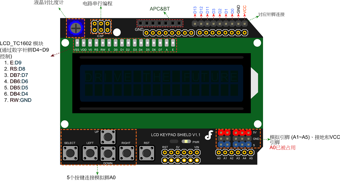
相比原来的LCD扩展板我们做了很多改进,使其融合LCD显示和IO端口扩展的功能。我们引出了更多有用的端口,包括A0到A5的3P模拟接口,Pin0到3,PIN11到13的数字接口。数字接口的边上,我们扩展了6pin无线通讯接口,提供了直插APC220或者Bluetooth V3模块的功能。电位器旁边,我们预留了ICSP的端口,用户可自己焊上排针。
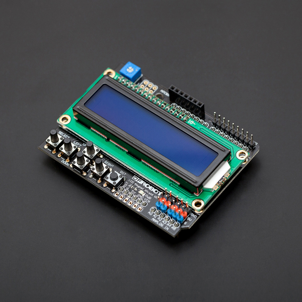
LCD Keypad Shield 是一款提供2行16字符液晶显示的Arduino扩展板。扩展了多个按键输入,可供用户作为LCD显示屏的菜单选择按键或者操控按键使用。一个扩展板就能让你与Arduino设备进行互动。我们还扩展Arduino Reset按键,方便用户进行软件调试。用户通过调节扩展板上的蓝色电位器,能够帮助您调节LCD屏的对比度。
对于Arduino初学者来说,不必为繁琐复杂液晶驱动电路连线而头疼了,这款LCD扩展板将电路简化,直接将此板插到Arduino Duemilanove 或 Uno控制器上即可使用,调用Arduino自带的LCD库,简单的几行代码便可以完成数据和字符的显示功能,有兴趣的朋友还能学习自定义显示内容。我们附送扩展板的按键功能库,LCD库(包含一个自制小游戏)。
注意:LCD Keypad shield v1.0选用的轻触开关是9.5mm长脚按键,便于用户自己使用LCD Keypad Shield搭建的Arduino数据监控平台或者小型操控平台封装在模具内。
产品参数
- 1602蓝色背景液晶(2行16字节)
- 具有LCD对比度调节功能
- 5个按键输入
- 扩展模拟信号传感器接口和数字口
- ICSP编程接口
- 具有APC220,蓝牙V3接口
- 尺寸:58x80mm
引脚说明
| 引脚 | 描述 |
|---|---|
| 模拟脚0 | 按钮 (选择, 上, 右, 下,左) |
| 数字脚4 | DB4 |
| 数字脚5 | DB5 |
| 数字脚6 | DB6 |
| 数字脚7 | DB7 |
| 数字脚8 | RS (数据或信号显示选择) |
| 数字脚9 | 使能(开始数据的读/ 写) |
| 数字脚10 | 背光控制 |
注意:
DB4\~7:为四位高阶、双向三态数据总线引脚。用于主控板和 LCD 之间的数据传输和接收A0已被占用
使用教程
实例一
样例代码
    #include <LiquidCrystal.h>

    /*******************************************************

    这个程序用来测试LCD液晶显示模块和5个按键。

    ********************************************************/

    // 选择LCD上使用到的引脚
    LiquidCrystal lcd(8, 9, 4, 5, 6, 7);

    // 定义各按键
    int lcd_key     = 0;
    int adc_key_in  = 0;

    #define btnRIGHT  0
    #define btnUP     1
    #define btnDOWN   2
    #define btnLEFT   3
    #define btnSELECT 4
    #define btnNONE   5

    //读取按键值
    int read_LCD_buttons()
    {
     adc_key_in = analogRead(0);          // 从模拟口0读值
     // 直接读到的5个按键值在以下值附近:0,144,329,504,741
     // 通过设定不同的阀值,就可以对应读到相应的按键
     if (adc_key_in > 1000) return btnNONE;
     if (adc_key_in < 50)   return btnRIGHT;
     if (adc_key_in < 250)  return btnUP;
     if (adc_key_in < 450)  return btnDOWN;
     if (adc_key_in < 650)  return btnLEFT;
     if (adc_key_in < 850)  return btnSELECT;

     // V1.0的版本使用以下的阀值:
    /*
     if (adc_key_in < 50)   return btnRIGHT;
     if (adc_key_in < 195)  return btnUP;
     if (adc_key_in < 380)  return btnDOWN;
     if (adc_key_in < 555)  return btnLEFT;
     if (adc_key_in < 790)  return btnSELECT;
    */

     return btnNONE;
    }

    void setup()
    {
     lcd.begin(16, 2);              // 开始
     lcd.setCursor(0,0);
     lcd.print("Push the buttons"); // 输出“Push the buttons”
    }

    void loop()
    {
     lcd.setCursor(9,1);            // 光标定在第二行,空开9格
     lcd.print(millis()/1000);      // 输出等待时间


     lcd.setCursor(0,1);            // 光标移动到第二行开头
     lcd_key = read_LCD_buttons();  // 读取按键

     switch (lcd_key)               // 选择按键
     {
       case btnRIGHT:
         {
         lcd.print("RIGHT ");
         break;
         }
       case btnLEFT:
         {
         lcd.print("LEFT   ");
         break;
         }
       case btnUP:
         {
         lcd.print("UP    ");
         break;
         }
       case btnDOWN:
         {
         lcd.print("DOWN  ");
         break;
         }
       case btnSELECT:
         {
         lcd.print("SELECT");
         break;
         }
         case btnNONE:
         {
         lcd.print("NONE  ");
         break;
         }
     }
    }
实例二
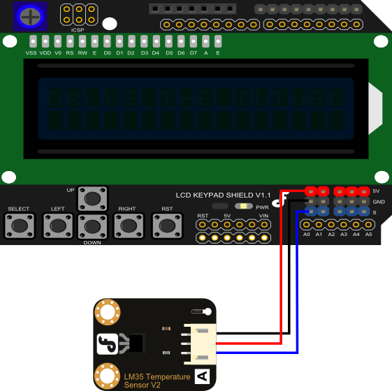
这个实例是从引脚1中读取一个模拟输入,然后显示在LCD屏幕上。这个实例中应用到了温度传感器LM35。
连接图
样例代码
/*******************************************************
Description:
Reads an analog input on pin 1, prints the result to the LCD.
This program takes the temperture sensor LM35 for example.
Connection:
Plug the LCD Keypad to the UNO(or other controllers)
Temperture sensor:
S(blue) -- A1()
Note: A0 has been occupied.
VCC(red) -- VCC
GND(black) -- GND
********************************************************/
#include <LiquidCrystal.h>
LiquidCrystal lcd(8, 9, 4, 5, 6, 7); // select the pins used on the LCD panel
unsigned long tepTimer ;
void setup(){
lcd.begin(16, 2); // start the library
}
void loop(){
lcd.setCursor(0, 0); // set the LCD cursor position
int val; // variable to store the value coming from the analog pin
double data; // variable to store the temperature value coming from the conversion formula
val=analogRead(1); // read the analog in value:
data = (double) val * (5/10.24); // temperature conversion formula
if(millis() - tepTimer > 500){ // output a temperature value per 500ms
tepTimer = millis();
// print the results to the lcd
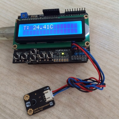
lcd.print("T: ");
lcd.print(data);
lcd.print("C");
}
}
显示结果
疑难解答
Q 1. WIKI 实例一的程序上传到 Edison 板子中,LCD 不正常工作,什么都不显示,怎么破? |
A: 解决方案见回复。关键点:IDE版本问题。解决方法:添加 pinMode(#, OUTPUT); 到setup() 函数中。
- 更多问题及有趣的应用,请访问论坛
更多

category: Product_Manual category: DFR_Series category: LCDs category:source category:Diagram