概 述
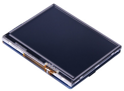
此液晶显示模块基于SPI通讯接口,提供3.5” TFT液晶显示, 电阻触摸屏,内置Flash闪存和SD卡外部扩展存储。
性能描述
- 产品型号: DM-TFT35-107
- 屏幕尺寸: 3.5"
- 工作电压: 3.3V和 5V
- 屏幕分辨率: 320x240
- 通信接口: SPI
- 闪存: 4MB
- 工作温度: -10~70℃
- 支持micro-SD卡
- 尺寸: 65.14*78.10 (W*H)mm
- 可视域:52.56*70.08(W*H)mm
- 重量:56.4g
- 支持 Arduino 和 mbed
引脚以及结构
1.引脚布局:该显示器采用TFT触摸,SPI接口,SD卡和外部FLASH存储器
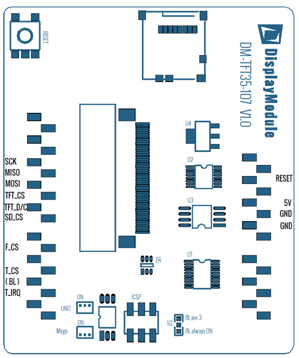
2.引脚功能:该TFT面板直接连接在一个Arduino引脚兼容的设备

3.电气特性

4.绝对最大额定值

基本应用
库文件实例应用下载
下面是下载库样例代码步骤。
1.首先下载库文件 dmtftlibrary
2.内容解压缩到你的Arduino库文件夹中。在Windows里找到这里通常位于Documents\Arduino\libraries。如果你想知道更多关于如何用Libraries,请关注Arduino的官方指南
3.开始打开Arduino的IDE,你可以找到现成的运行实例中的菜单。File--> Examples-> DmTftLibraries,选择相对应模块使用。
4.打开范例和上传到你的Arduino电路板。

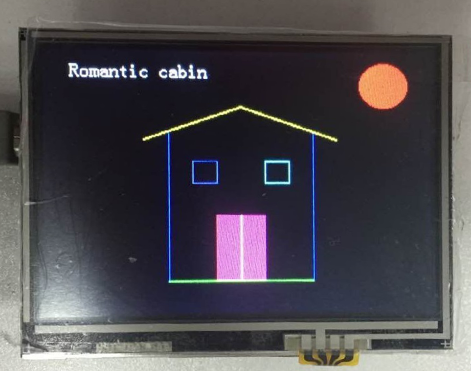
基本显示应用
基本显示应用既是显示字符、线条、图形等基本操作。先从库中找到libraries\DmTftLibrary\DmTftBase.h文件,调用基本函数。
	#include <SPI.h>
	#include <DmTftSsd2119.h>
	DmTftSsd2119 tft = DmTftSsd2119(10, 9);//定义函数体
	void setup ()
	{
  		tft.init();//Initialization screen
 		tft.drawString(5, 10,"  Romantic cabin");//显示字符串
	 	int x=160,y=50;
 		tft.drawLine (x, y, x-80, y+30, YELLOW );//画线
 		delay(1000);
 		tft.drawLine (x, y, x+80, y+30, YELLOW );
 		delay(1000);
 		tft.drawLine (x-60, y+25, x-60, y+160, BLUE  );
 		delay(1000);
 		tft.drawLine (x+60, y+25, x+60, y+160, BLUE  );
 		delay(1000);
 		tft.drawLine (x-60, y+160, x+60, y+160,0x07e0  );
 		delay(1000);
  		tft.drawRectangle(x-40, y+50,x-20, y+70, 0x8418); //显示方形
  		delay(1000);
  		tft.drawRectangle(x+40, y+50,x+20, y+70, 0x07ff);
  		delay(1000);
  		tft.fillRectangle(x-20, y+100, x+20, y+160, BRIGHT_RED);//显示充满的方形
  		delay(1000);
  		tft.drawLine (x, y+100, x, y+160, WHITE  );
  		delay(1000);

  		tft.fillCircle(x+120, y-20, 20, RED );//显示圆形
  		delay(1000);
	}
	void loop() { }
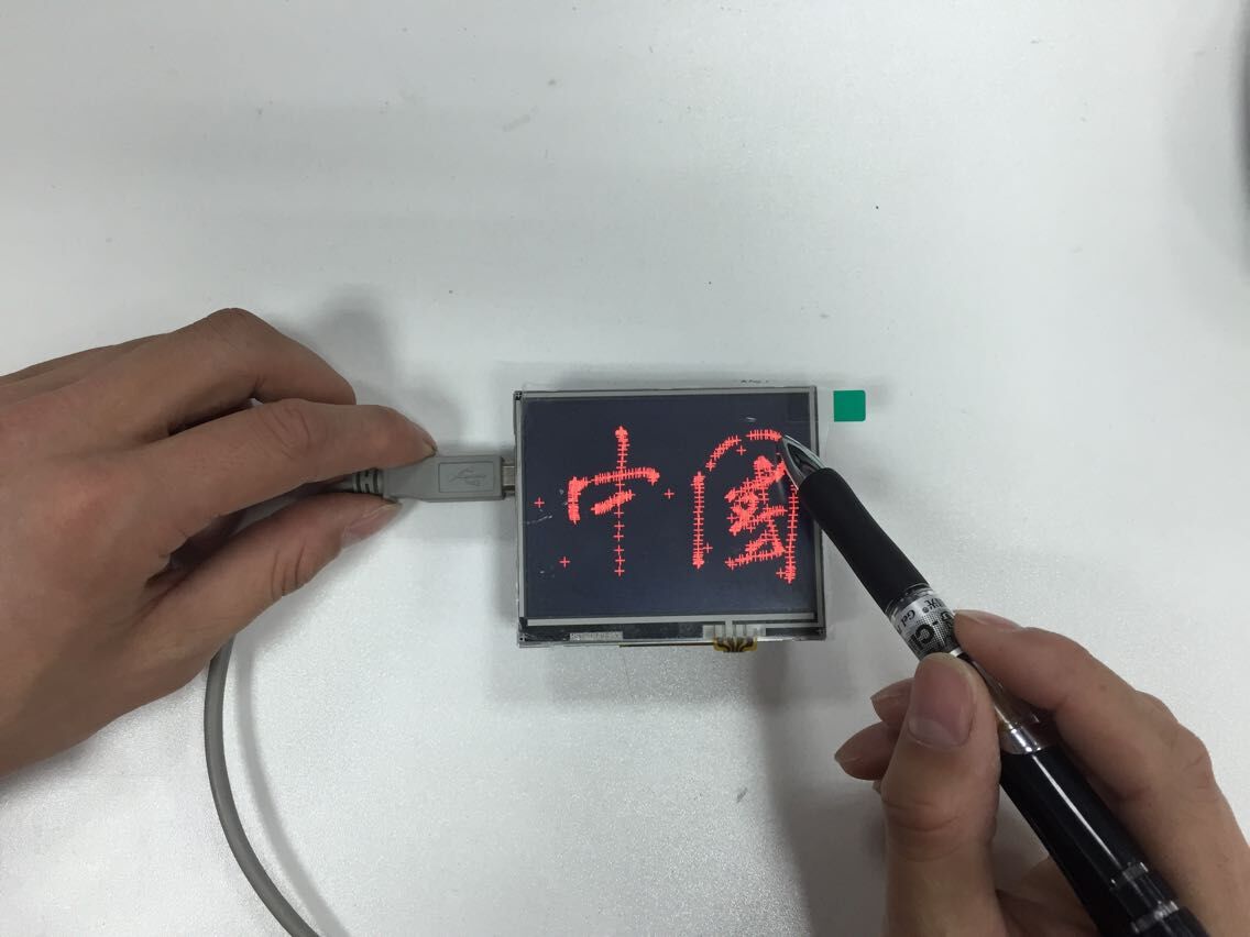
触屏应用
触屏应用既是能够获取到触点的位置
	#include <SPI.h>
	#include <DmTftSsd2119.h>
	#include <DmTouch.h>
	#include <utility/DmTouchCalibration.h>
	DmTftSsd2119 tft = DmTftSsd2119();
	DmTouch dmTouch = DmTouch(DmTouch::DM_TFT35_107);
	DmTouchCalibration calibration = DmTouchCalibration(&tft, &dmTouch);
	bool calibrated = false;
	void setup() {
 		dmTouch.setCalibrationMatrix(calibration.getDefaultCalibrationData((int)DmTouch::DM_TFT35_107));
	 	tft.init();
	 	dmTouch.init();
	}
	void loop()
	{
		 uint16_t x, y ;
		 bool touched = true;
		 if (dmTouch.isTouched()) {
		   dmTouch.readTouchData(x,y,touched);//读取触点的x、y坐标
		   calibration.drawCalibPoint(x, y);//在触点出显示显示
		 }
	}
从SD卡显示图片应用
1.在arduino上请使用这个转换软件把原bmp图片(小于屏幕分辨率:320x240)转换成16bit 565格式bmp图片才能正常显示,再把图片放到SD卡中,也可以直接用库里的图片(arduino-1.0.6\libraries\DmTftLibrary\examples\DM-TFT35-107)

2.把SD卡装到TFT屏上[注意有的SD卡读不了(不显示或只能读取一部分),换一个知名厂家出的SD卡]
3.再按照1-4基本步骤(库文件实例应用下载)把SD卡相应的程序下载到控制器中,或者下载下面的程序(注意要改相应的图片名称)。
#include <SPI.h>
#include <SPIFlash.h>
#include <SD.h>
#include <DmTftSsd2119.h>
#include <DmDrawBmpFromSdCard.h>
#define TFT_CS  10
#define SD_CS   8
#define F_CS    6
#define T_CS    4
DmTftSsd2119 tft = DmTftSsd2119(10, 9);
DmDrawBmpFromSdCard drawImage = DmDrawBmpFromSdCard();
void setup()
{
pinMode(TFT_CS, OUTPUT); // Set CS SPI pin HIGH for all SPI units, so they don't interfere
digitalWrite(TFT_CS, HIGH);
pinMode(T_CS, OUTPUT);
digitalWrite(T_CS, HIGH);
pinMode(SD_CS, OUTPUT);
digitalWrite(SD_CS, HIGH);
pinMode(F_CS, OUTPUT);
digitalWrite(F_CS, HIGH);
Serial.begin(9600);
tft.init();
SD.begin(SD_CS);
drawImage.drawImage("logol565.bmp", tft, 0, 0);//显示图片
delay(6000);
drawImage.drawImage("logo1888.bmp", tft, 0, 0);
delay(6000);
}
void loop() {}
相关产品的应用
常见问题
问:触摸屏使用时候会断触,然后便不能继续写,如何解决?
答:保证供电电源输出稳定。
 购买
购买