概 述
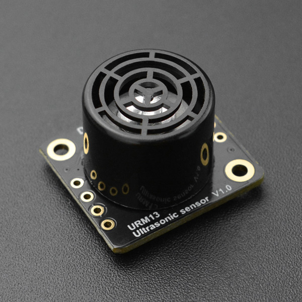
URM13是一款开放式单探头超声波测距传感器,支持TRIG脉冲触发测距(兼容SR04)、UART和I2C,传感器可以在三种接口模式间无缝切换。该传感器尺寸紧凑、并且兼容如Arduino、树莓派等各种3.3V或5V主控板,非常方便用户集成和应用,UART模式使用标准Modbus-RTU协议并集成了收发控制输出,可简单通过外接RS485收发器扩展RS485接口。该传感器在保持同类传感器尺寸及重量优势的同时还具有非常出色的测距灵敏度,使得他对于一些低声波反射率的探测目标同样具备超越同类传感器的探测性能。URM13传感器会在每次测距时自动检测环境及电源噪声并以此来动态调节测量参数,确保它能在各种复杂应用场景之下依旧能够稳定工作。
为了满足不同的用户需求,URM13内置两段测距量程:
1、小量程15-150cm:可以实现高达50HZ的高频率探测,适用于室内机器人避障等场景。
2、大量程40-900cm:具有卓越的测量灵敏度,测量频率为常规10HZ,适用于空旷场景或需要高灵敏度、高量程距离探测的场景。
实际使用时,可通过重复触发2段量程的测距,以实现整个量程的检测。
技术参数
- 工作电压:3.3~5.5V DC
- 最大瞬时电流:350mA
- 有效量程:15cm ~ 900cm
- 距离分辨率:1cm
- 距离误差:±1%
- 温度分辨率:0.1℃
- 温度误差:±1℃
- 测量频率:10HZ
- 工作温度:-10℃~+70℃
- 工作湿度范围:RH<75%
- 传感器声学频率:40±1KHz
- 传感器方向角:60°(-6dB)
- 通信接口:I2C&TRIG/UART(Modbus-RTU)
接口及尺寸
- 尺寸示意图:
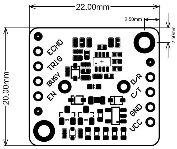
- 接口描述:
URM13可以在IIC、UART两种通信接口间任意切换,用户可以根据实际需求进行切换,并且传感器会保存已设置好的通信接口类型,下次使用时,不用再次设置。
接口引脚说明如下:
| 引脚 | 默认功能(UART) | 复用功能 (I2C) | 说明 |
|---|---|---|---|
| VCC | 电源正 | 电源正 | 3.3~5.5V |
| GND | 电源地 | 电源地 | GND |
| C/T | UART-TX | I2C-SCL | 传感器出厂默认为UART接口,若需要用I2C接口,参考模式切换。(端口模式为开漏,内部上拉6.2K电阻到VCC) |
| D/R | UART-RX | I2C-SDA | 传感器出厂默认为UART接口,若需要用I2C接口,参考模式切换。(端口模式为开漏,内部上拉6.2K电阻到VCC) |
| EN | 电源使能 | 电源使能 | 该引脚作为电源的使能脚,内部上拉,将EN拉低可以关断传感器电源,若不用此功能该引脚可以悬空不接。 |
| BUSY | RS485收发控制口 | BUSY(开漏输出) | 在UART模式下,该引脚可作为RS485收发控制口,外接一个RS485的驱动IC即可扩展得到RS485接口。 在I2C模式下,测距过程中BUSY端口将拉低,BUSY脚输出高表示空闲或上一次测距已经完成。该引脚可接到主机的中断口,在BUSY端口输出电平上升沿时可以及时的读取到传感器数据。 |
| TRIG | NC | TRIG | - UART接口下未使用 I2C接口下作为外部端口测距触发引脚,上升沿触发。 |
| ECHO | NC | ECHO | - UART接口下未使用 I2C接口下,当传感器测距功能被触发后,该脚引输出一个高脉宽,此脉宽代表超声波传播时间(单位:us)。 |
板载LED灯状态指示
- 在传感器上电后,LED灯闪烁1次,表示当前传感器为UART模式,此模式下每收到一次正确的主机命令时LED会闪烁1次。
- 在传感器上电后,LED灯闪烁2次,表示当前传感器为I2C模式,此模式下测距时LED闪烁1次。
TRIG脉冲触发示例
准备
- 说明
使用此模式的驱动方式与SR04相同,在TRIG端口输入一个脉冲电平将触发传感器测距,测距完成后ECHO端口将输出一段脉冲电平,输出脉冲电平的宽度等于超声波的测量往返飞行时间。
需要特别说明一下:
1、TRIG模式下无法做量程切换,需要使用I2C接口配置或切换。
2、TRIG模式下输出的脉冲宽度未做温度补偿。
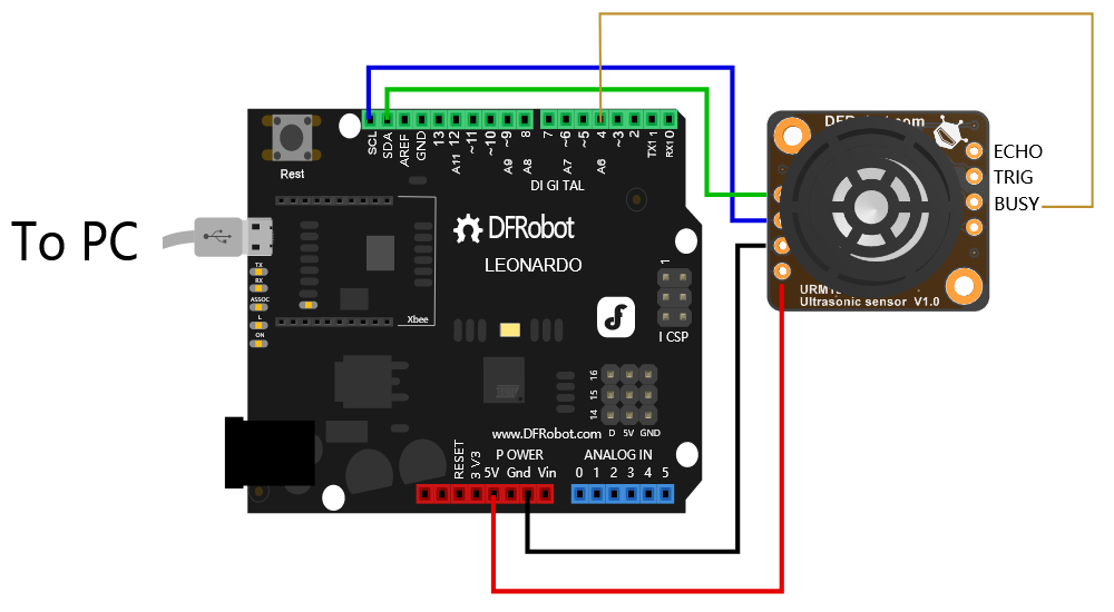
- 使用该模式前,请确认传感器为I2C模式,且为被动测距模式(I2C配置寄存器Bit2 = 1)
- 硬件
- 1 x Arduino Leonardo控制板
- 1 x USB数据线(USB数据线一端连接Arduino板USB口,另一端连接至电脑USB口)
- 软件
- Arduino IDE, 点击下载Arduino IDE
- 在IDE中打开Library Manager(Ctrl+Shift+I),搜索并安装DFRobot_URM13库
- 硬件接线示意图

-
时序图

-
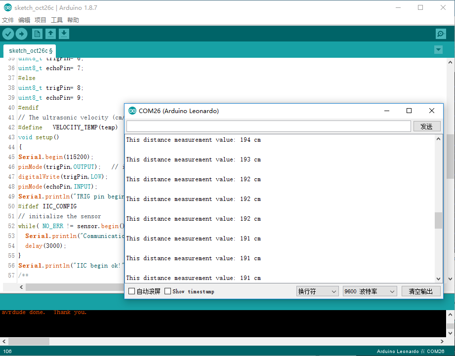
基于库示例代码
/*!
 * @file  URM13WorkInTRIG.ino
 * @brief  This demo shows how URM13 works in TRIG interface mode.
 * @n      can obtain the sensor current distance value and change its parameters through IIC
 * @copyright  Copyright (c) 2010 DFRobot Co.Ltd (http://www.dfrobot.com)
 * @license  The MIT License (MIT)
 * @author  [qsjhyy](yihuan.huang@dfrobot.com)
 * @version  V1.0.0
 * @date  2021-09-18
 * @url  https://github.com/DFRobot/DFRobot_URM13
 */
#include <DFRobot_URM13.h>
/*!
 * UART(Modbus-RTU) and I2C/TRIG mode switch
 * URM13sensor default setting is in UART mode. the sensor can switch between I2C and UART modes simply by short-circuiting different pins before power-on:

 * I2C/TRIG: Short-circuit TRIG and ECHO pins before the sensor is powered on. After the sensor is powered on, that the LED flashes twice indicates the sensor has switched to I2C mode.
 * UART(Modbus-RTU): Short-circuit TRIG and BUSY pins before the sensor is powered on. After the sensor is powered on, that the LED flashes once indicates the sensor has switched to UART(Modbus-RTU) mode.
 * After the mode switch succeeds, users can disconnect the corresponding pin short-circuiting, and the switched mode will be recorded by the sensor and take effect permanently.
 */
/* if you want to use IIC to change sensor parameters and mode, open the macro and configure the following api */
// #define IIC_CONFIG
#ifdef IIC_CONFIG
  /* instantiate an object with IIC communication to drive the sensor */
  DFRobot_URM13_IIC sensor(/*iicAddr = */0x12, /*iicBus = */&Wire);
#endif
/*
 * trigPin   in I2C interface mode, to measure distance and trigger pin as external port, rising edge trigger
 * echoPin   in I2C interface mode, when the sensor ranging function is triggered, the pin outputs a high pulse-width, which represents the ultrasonic transmission time (unit:us)
 */
#if defined(ESP32) || defined(ESP8266)
  uint8_t trigPin = D2;
  uint8_t echoPin = D3;
#elif defined(ARDUINO_SAM_ZERO)
  uint8_t trigPin= 6;
  uint8_t echoPin= 7;
#else
  uint8_t trigPin= 8;
  uint8_t echoPin= 9;
#endif
// The ultrasonic velocity (cm/us) compensated by temperature
#define   VELOCITY_TEMP(temp)   ( ( 331.5 + 0.6 * (float)( temp ) ) * 100 / 1000000.0 )
void setup()
{
  Serial.begin(115200);
  pinMode(trigPin,OUTPUT);   // initialize trigPin and two IO interfaces of echoPin
  digitalWrite(trigPin,LOW);
  pinMode(echoPin,INPUT);
  Serial.println("TRIG pin begin ok!");
#ifdef IIC_CONFIG
  // initialize the sensor
  while( NO_ERR != sensor.begin() ){
    Serial.println("Communication with device failed, please check connection");
    delay(3000);
  }
  Serial.println("IIC begin ok!");
  /**
   * set measure mode
   * mode measure mode to be set, the following patterns constitute mode mode:
   *   eInternalTemp: use internal temperature compensation function, eExternalTemp: use external temperature compensation function (users need to write external temperature)
   *   eTempCompModeEn: enable temperature compensation function, eTempCompModeDis: disable temperature compensation function
   *   eAutoMeasureModeEn: automatic ranging, eAutoMeasureModeDis: passive ranging
   *   eMeasureRangeModeLong: large range measurement(40 - 900cm), eMeasureRangeModeShort: small range measurement(15-150cm)
   */
  sensor.setMeasureMode(sensor.eInternalTemp | \
                        sensor.eTempCompModeEn | \
                        sensor.eAutoMeasureModeDis | \
                        sensor.eMeasureRangeModeLong);

  /**
   * note: the api makes external temperature compensation function meaningful only when setting measure mode
   * write ambient temperature data for external temperature compensation, the setting is invalid when out of range
   * temp written ambient temperature data, unit is ℃, resolution is 0.1℃, signed number, range:-10℃~+70℃
   */
  sensor.setExternalTempretureC(30.0);
  /**
   * ranging sensitivity setting, 0x00-0x0A:sensitivity level 0-10
   * mode to set the sensor ranging sensitivity in large range (40-900cm), the smaller the value, and the higher the sensitivity, power off to save the settings, and it takes effect at once
   */
  sensor.setMeasureSensitivity(0x00);
#endif
  delay(1000);
}
void loop()
{
  uint16_t  pulseWidthUs, distanceCm;
  digitalWrite(trigPin,HIGH);   // Set the tirgPin High
  delayMicroseconds(50);         // Delay of 50 microseconds
  digitalWrite(trigPin,LOW);    // Set the tirgPin Low

  /**
   * Measure echo high level time, the output high level time represents the ultrasonic flight time (unit: us)
   * The distance can be calculated according to the flight time of ultrasonic wave,
   * and the ultrasonic sound speed can be compensated according to the actual ambient temperature
   */
  pulseWidthUs = pulseIn(echoPin,HIGH);
  delayMicroseconds(50);   // Delay of 50 microseconds
  distanceCm = (uint16_t)(pulseWidthUs * VELOCITY_TEMP(30.0) / 2.0);

  Serial.print("This distance measurement value: ");
  Serial.print(distanceCm);
  Serial.println(" cm");

  Serial.println();
  delay(1000);
}
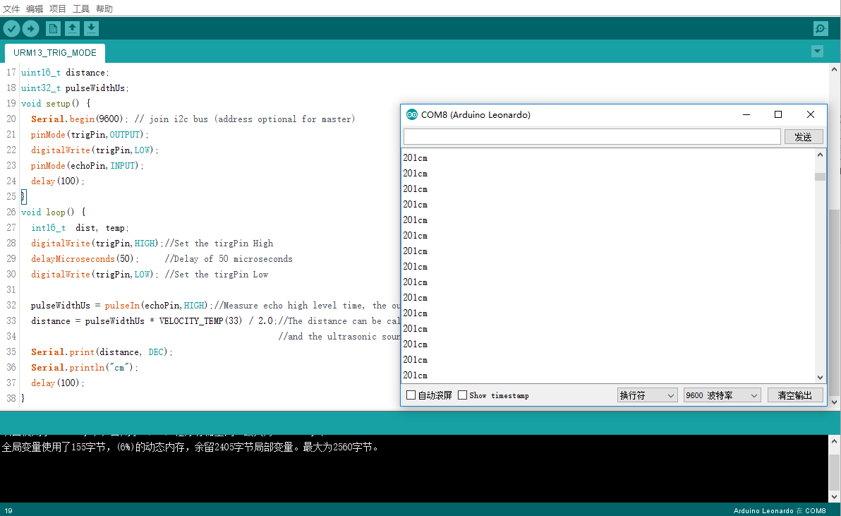
- 示例代码(未使用库)
#define    VELOCITY_TEMP(temp)       ( ( 331.5 + 0.6 * (float)( temp ) ) * 100 / 1000000.0 ) // The ultrasonic velocity (cm/us) compensated by temperature
int16_t trigPin = 5;
int16_t echoPin = 6;
uint16_t distance;
uint32_t pulseWidthUs;
void setup() {
  Serial.begin(9600);
  pinMode(trigPin,OUTPUT);
  digitalWrite(trigPin,LOW);
  pinMode(echoPin,INPUT);
  delay(100);
}
void loop() {
  int16_t  dist, temp;
  digitalWrite(trigPin,HIGH);//Set the tirgPin High
  delayMicroseconds(50);     //Delay of 50 microseconds
  digitalWrite(trigPin,LOW); //Set the tirgPin Low

  pulseWidthUs = pulseIn(echoPin,HIGH);//Measure echo high level time, the output high level time represents the ultrasonic flight time (unit: us)
  distance = pulseWidthUs * VELOCITY_TEMP(33) / 2.0;//The distance can be calculated according to the flight time of ultrasonic wave,/
                                                    //and the ultrasonic sound speed can be compensated according to the actual ambient temperature
  Serial.print(distance, DEC);
  Serial.println("cm");
  delay(100);
}
UART与I2C模式切换
URM13传感器默认出厂设置为UART模式。
传感器可以在I2C、UART两种模式间通过上电前短接不同的引脚实现简单的模式切换:
- 在传感器上电前,将TRIG与ECHO引脚短接,上电后LED闪烁2次,表示传感器已切换为I2C模式。
- 在传感器上电前,将TRIG与BUSY引脚短接,上电后LED闪烁1次,表示传感器已切换为UART模式。
在模式切换成功后,用户即可断开对应引脚的短接,切换后的模式将被传感器记录保存,永久生效。
UART寄存器说明
UART接口下,传感器为Modbus从机,主机需要通过Modbus协议与传感器进行通信。
| 地址 | 数量 | 名称 | 读写 | 数据范围 | 默认值 | 数据说明 |
|---|---|---|---|---|---|---|
| 0x00 | 1 | 模块PID寄存器 | R | 0x0000-0xFFFF | 0x0003 | 该位用于产品校验[可实现模块类型的检测] |
| 0x01 | 1 | 模块VID寄存器 | R | 0x0000-0xFFFF | 0x0010 | 该位用于版本校验[0x0010表示V0.0.1.0] |
| 0x02 | 1 | 模块地址寄存器 | R/W | 0x0001-0x00F7 | 0x000D | [传感器地址未知时,可通过广播地址0x00做写入寄存器操作,此时传感器不会有数据输出] 断电保存,重启后生效 |
| 0x03 | 1 | 串口参数控制寄存器1 | R/W | 0x0000-0xFFFF | 0x0005 | 模块波特率 0x0001---2400 0x0003---9600 0x0004---14400 0x0005---19200 0x0006---38400 0x0007---57600 0x0008---115200 Other----115200 断电保存,重启后生效 |
| 0x04 | 1 | 串口参数控制寄存器2 | R/W | 0x0000-0xFFFF | 0x0001 | 模块校验位H 停止位L 0x00--无 0x00--0.5Byte 0x01--Even 0x01--1Byte 0x02--Odd 0x02--1.5Byte Other--无 0x03--2Byte Other--1Byte 断电保存,重启后生效 |
| 0x05 | 1 | 距离寄存器 | R | 0x0000-0xFFFF | 0xFFFF | 模块测得的距离值LSB代表1cm |
| 0x06 | 1 | 板载温度数据寄存器 | R | 0x0000-0xFFFF | 0x0000 | 板载温度传感器测得的温度数据LSB代表0.1摄氏度(有符号数) |
| 0x07 | 1 | 外部温度补偿数据寄存器 | R/W | 0x0000-0xFFFF | 0x0000 | 写入环境温度数据到该寄存器用于外部温度补偿LSB代表0.1摄氏度(有符号数) |
| 0x08 | 1 | 控制寄存器 | R/W | 0x0000-0xFFFF | 0x0004 | bit0 0-使用板载温度补偿功能 1-使用外部温度补偿功能(需用户写入温度数据至外部温度补偿数据寄存器) bit1 0-开启温度补偿功能 1-关闭温度补偿功能 bit2 0-自动测距 1-被动测距 bit3 被动模式下,向该位写入1,传感器将完成一次测距,测距完成后(约100ms)可从距离寄存器读出距离值,自动测距模式下该位保留。该位置1后将自动清0 bit4 0-大量程测距(40-900cm) 1-小量程测距(15-150cm) 断电保存,立即生效 |
| 0x09 | 1 | 电源噪声等级寄存器 | R | 0x0000-0x0A | 0x0000 | 0x0000-0x000A对应噪声等级0-10 该参数能够反映供电电源以及环境对传感器的影响程度。噪声等级越小,传感器得到的距离值将更精准。 |
| 0x0A | 1 | 测距灵敏度设置寄存器 | R/W | 0x0000-0x0A | 0x0000 | 0x0000-0x000A:灵敏度等级0-10 设置传感器大量程段(40-900cm)的测距灵敏度,该值越小,灵敏度越高 断电保存,立即生效 |
UART模式Arduino示例
准备
- 硬件
- 1 x Arduino Leonardo控制板
- 1 x USB数据线(USB数据线一端连接Arduino板USB口,另一端连接至电脑USB口)
- 软件
- Arduino IDE, 点击下载Arduino IDE
- 在IDE中打开Library Manager(Ctrl+Shift+I),搜索并安装DFRobot_URM13和DFRobot_RTU两个库
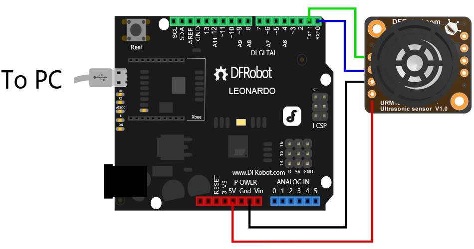
- 硬件接线示意图
基于库示例代码
/*!
* @file URM13WorkInModbus.ino
* @brief This demo shows how URM13 works in Modbus-RTU interface mode.
* @n can obtain and change the sensor basic information, configure parameters and get the current distance value and current temperature value
* @n Note: because the called DFRobot_RTU library does't support microbit, this demo does't support microbit either
* @copyright Copyright (c) 2010 DFRobot Co.Ltd (http://www.dfrobot.com)
* @license The MIT License (MIT)
* @author [qsjhyy](yihuan.huang@dfrobot.com)
* @version V1.0.0
* @date 2021-09-18
* @url https://github.com/DFRobot/DFRobot_URM13
*/
#include <DFRobot_URM13.h>
#if defined(ARDUINO_AVR_UNO)||defined(ESP8266)
#include <SoftwareSerial.h>
#endif
/*!
* UART(Modbus-RTU) and I2C/TRIG mode switch
* URM13sensor default setting is in UART mode. the sensor can switch between I2C and UART modes simply by short-circuiting different pins before power-on:
* I2C/TRIG: Short-circuit TRIG and ECHO pins before the sensor is powered on. After the sensor is powered on, that the LED flashes twice indicates the sensor has switched to I2C mode.
* UART(Modbus-RTU): Short-circuit TRIG and BUSY pins before the sensor is powered on. After the sensor is powered on, that the LED flashes once indicates the sensor has switched to UART(Modbus-RTU) mode.
* After the mode switch succeeds, users can disconnect the corresponding pin short-circuiting, and the switched mode will be recorded by the sensor and take effect permanently.
*/
#define DEFAULT_DEVICE_ADDRESS 0x000D
/**
* @brief DFRobot_URM13_RTU constructor
* @param addr: modbus slave address(range1~247)or broadcast address(0x00),if it's set to a broadcast address, send a broadcast packet, and all slaves on bus will process it but not respond
* @param s : a serial port pointer to Stream
*/
#if defined(ARDUINO_AVR_UNO)||defined(ESP8266)
SoftwareSerial mySerial(/*rx =*/4, /*tx =*/5);
DFRobot_URM13_RTU sensor(/*s =*/&mySerial, /*addr =*/DEFAULT_DEVICE_ADDRESS);
#else
DFRobot_URM13_RTU sensor(/*s =*/&Serial1, /*addr =*/DEFAULT_DEVICE_ADDRESS);
#endif
void setup()
{
Serial.begin(115200);
#if defined(ARDUINO_AVR_UNO)||defined(ESP8266)
mySerial.begin(19200); // excessive baud rate of UNO soft serial port will makes communication unstable. 9600 is recommended.
#elif defined(ESP32)
Serial1.begin(19200, SERIAL_8N1, /*rx =*/D3, /*tx =*/D2);
#else
Serial1.begin(19200);
#endif
// initialize the sensor
while( NO_ERR != sensor.begin() ){
Serial.println("Communication with device failed, please check connection");
delay(3000);
}
Serial.println("Begin ok!");
/**
* retrieve basic information from the sensor and buffer it into basicInfoRTU, the structure that stores information
*/
sensor.refreshBasicInfo();
/* module PID, default value is 0x03 the bit is used for product check[can detect the sensor type] */
Serial.print("PID: 0x0");
Serial.println(sensor.basicInfoRTU.PID, HEX);
/* module VID, firmware revision number:0x10 represents V1.0 */
Serial.print("VID: 0x");
Serial.println(sensor.basicInfoRTU.VID, HEX);
/* module Modbus-RTU slave address, default value is 0x0D, module device address(1~247) */
Serial.print("mailing address: 0x0");
Serial.println(sensor.basicInfoRTU.addr, HEX);
/* module baud rate,default value is 0x0005:
* 0x0001---2400 0x0002---4800 0x0003---9600 0x0004---14400 0x0005---19200
* 0x0006---38400 0x0007---57600 0x0008---115200 */
Serial.print("baudrate: 0x0");
Serial.println(sensor.basicInfoRTU.baudrate, HEX);
/* check bit and stop bit of the module,default value is 0x0001
* check bit: 0 represents none; 1 represents even; 2 represents odd
* stop bit: 0.5bit; 1bit; 1.5bit; 2bit */
Serial.print("check bit: ");
Serial.println(sensor.basicInfoRTU.checkbit);
Serial.print("stop bit: ");
Serial.println((sensor.basicInfoRTU.stopbit + 1.0) / 2.0, 1);
/**
* set the module communication address, power off to save the settings, and restart for the settings to take effect
* addr device address to be set, Modbus-RTU address range(1~247 is 0x01~0xF7)
*/
sensor.setADDR(0x0D);
/**
* UART interface mode, set module baud rate, the setting takes effect after power fail and restart, the default is 19200
* addr the baud rate to be set:
* eBaudrate2400---2400, eBaudrate4800---4800, eBaudrate9600---9600,
* eBaudrate14400---14400, eBaudrate19200---19200, eBaudrate38400---38400,
* eBaudrate57600---57600, eBaudrate115200---115200
*/
sensor.setBaudrateMode(sensor.eBaudrate19200);
/**
* UART interface mode, set check bit and stop bit of the module
* mode the mode to be set, the following patterns constitute mode:
* check bit:
* eCheckBitNone
* eCheckBitEven
* eCheckBitOdd
* stop bit:
* eStopBit0P5
* eStopBit1
* eStopBit1P5
* eStopBit2
*/
sensor.setCheckbitStopbit(sensor.eCheckBitNone | sensor.eStopBit1);
/**
* set measure mode
* mode measure mode to be set, the following patterns constitute mode:
* eInternalTemp: use internal temperature compensation function, eExternalTemp: use external temperature compensation function (users need to write external temperature)
* eTempCompModeEn: enable temperature compensation function, eTempCompModeDis: disable temperature compensation function
* eAutoMeasureModeEn: automatic ranging, eAutoMeasureModeDis: passive ranging
* eMeasureRangeModeLong: large range measurement(40 - 900cm), eMeasureRangeModeShort: small range measurement(15-150cm)
*/
sensor.setMeasureMode(sensor.eInternalTemp | \
sensor.eTempCompModeEn | \
sensor.eAutoMeasureModeDis | \
sensor.eMeasureRangeModeLong);
/**
* note: the api makes external temperature compensation function meaningful only when setting measure mode
* write ambient temperature data for external temperature compensation, the setting is invalid when out of range
* temp written ambient temperature data, unit is ℃, resolution is 0.1℃, signed number, range:-10℃~+70℃
*/
sensor.setExternalTempretureC(30.0);
/**
* ranging sensitivity setting, 0x00-0x0A:sensitivity level 0-10
* mode to set the sensor ranging sensitivity in large range (40-900cm), the smaller the value, and the higher the sensitivity, power off to save the settings, and it takes effect at once
*/
sensor.setMeasureSensitivity(0x00);
Serial.println();
delay(1000);
}
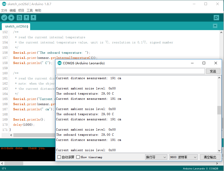
void loop()
{
/**
* the function to trigger measuring in passive measurement mode
* in passive measurement mode, the function is called once, the ranging command is sent once, and the module measures the distance once and saves the measured value into the distance register
*/
sensor.passiveMeasurementTRIG();
/**
* get noise level of power supply, the smaller the noise level, the more accurate the distance value obtained by the sensor
* the parameter indicates the influence of power supply and environment on the sensor. 0x00-0x0A matches noise level of 0-10.
*/
Serial.print("Current ambient noise level: 0x0");
Serial.println(sensor.getNoiseLevel(), HEX);
/**
* read the current internal temperature
* the current internal temperature value, unit is ℃, resolution is 0.1℃, signed number
*/
Serial.print("The onboard temperature: ");
Serial.print(sensor.getInternalTempretureC());
Serial.println(" C");
/**
* read the current distance value, the value of zero indicates it's not measured within the range
* note: when the object is not in the sensor ranging range, the read measured data will be meaningless
* the current distance value, unit is cm, large range(40 - 900cm)small range(15-150cm)
*/
Serial.print("Current distance measurement: ");
Serial.print(sensor.getDistanceCm());
Serial.println(" cm");
Serial.println();
delay(1000);
}
基于Arduino串口发送命令示例代码
/**************************************************************************************************************
This code tests the range finder function of the URM13 ultrasonic sensor
@ author : roker.wang@dfrobot.com
@ data : 21.08.2020
@ version: 1.0
**************************************************************************************************************/
#define SLAVE_ADDR ((uint16_t)0x0D)
#define TEMP_CPT_SEL_BIT ((uint16_t)0x01 << 0)
#define TEMP_CPT_ENABLE_BIT ((uint16_t)0x01 << 1)
#define MEASURE_MODE_BIT ((uint16_t)0x01 << 2)
#define MEASURE_TRIG_BIT ((uint16_t)0x01 << 3)
#define MEASURE_RANGE_BIT ((uint16_t)0x01 << 4)
#define MB_OP_WRITE_SINGLE_HOLDING_REG ((uint8_t)0x06)
#define MB_OP_READ_HOLDING_REGS ((uint8_t)0x03)
typedef enum {
ePid,
eVid,
eAddr,
eComBaudrate,
eComParityStop,
eDistance,
eInternalTempreture,
eExternTempreture,
eControl,
eNoise,
eSensitivity
} eRegIndex_t; //Sensor register index
static const uint8_t aucCRCHi[] = {
0x00, 0xC1, 0x81, 0x40, 0x01, 0xC0, 0x80, 0x41, 0x01, 0xC0, 0x80, 0x41,
0x00, 0xC1, 0x81, 0x40, 0x01, 0xC0, 0x80, 0x41, 0x00, 0xC1, 0x81, 0x40,
0x00, 0xC1, 0x81, 0x40, 0x01, 0xC0, 0x80, 0x41, 0x01, 0xC0, 0x80, 0x41,
0x00, 0xC1, 0x81, 0x40, 0x00, 0xC1, 0x81, 0x40, 0x01, 0xC0, 0x80, 0x41,
0x00, 0xC1, 0x81, 0x40, 0x01, 0xC0, 0x80, 0x41, 0x01, 0xC0, 0x80, 0x41,
0x00, 0xC1, 0x81, 0x40, 0x01, 0xC0, 0x80, 0x41, 0x00, 0xC1, 0x81, 0x40,
0x00, 0xC1, 0x81, 0x40, 0x01, 0xC0, 0x80, 0x41, 0x00, 0xC1, 0x81, 0x40,
0x01, 0xC0, 0x80, 0x41, 0x01, 0xC0, 0x80, 0x41, 0x00, 0xC1, 0x81, 0x40,
0x00, 0xC1, 0x81, 0x40, 0x01, 0xC0, 0x80, 0x41, 0x01, 0xC0, 0x80, 0x41,
0x00, 0xC1, 0x81, 0x40, 0x01, 0xC0, 0x80, 0x41, 0x00, 0xC1, 0x81, 0x40,
0x00, 0xC1, 0x81, 0x40, 0x01, 0xC0, 0x80, 0x41, 0x01, 0xC0, 0x80, 0x41,
0x00, 0xC1, 0x81, 0x40, 0x00, 0xC1, 0x81, 0x40, 0x01, 0xC0, 0x80, 0x41,
0x00, 0xC1, 0x81, 0x40, 0x01, 0xC0, 0x80, 0x41, 0x01, 0xC0, 0x80, 0x41,
0x00, 0xC1, 0x81, 0x40, 0x00, 0xC1, 0x81, 0x40, 0x01, 0xC0, 0x80, 0x41,
0x01, 0xC0, 0x80, 0x41, 0x00, 0xC1, 0x81, 0x40, 0x01, 0xC0, 0x80, 0x41,
0x00, 0xC1, 0x81, 0x40, 0x00, 0xC1, 0x81, 0x40, 0x01, 0xC0, 0x80, 0x41,
0x00, 0xC1, 0x81, 0x40, 0x01, 0xC0, 0x80, 0x41, 0x01, 0xC0, 0x80, 0x41,
0x00, 0xC1, 0x81, 0x40, 0x01, 0xC0, 0x80, 0x41, 0x00, 0xC1, 0x81, 0x40,
0x00, 0xC1, 0x81, 0x40, 0x01, 0xC0, 0x80, 0x41, 0x01, 0xC0, 0x80, 0x41,
0x00, 0xC1, 0x81, 0x40, 0x00, 0xC1, 0x81, 0x40, 0x01, 0xC0, 0x80, 0x41,
0x00, 0xC1, 0x81, 0x40, 0x01, 0xC0, 0x80, 0x41, 0x01, 0xC0, 0x80, 0x41,
0x00, 0xC1, 0x81, 0x40
};
static const uint8_t aucCRCLo[] = {
0x00, 0xC0, 0xC1, 0x01, 0xC3, 0x03, 0x02, 0xC2, 0xC6, 0x06, 0x07, 0xC7,
0x05, 0xC5, 0xC4, 0x04, 0xCC, 0x0C, 0x0D, 0xCD, 0x0F, 0xCF, 0xCE, 0x0E,
0x0A, 0xCA, 0xCB, 0x0B, 0xC9, 0x09, 0x08, 0xC8, 0xD8, 0x18, 0x19, 0xD9,
0x1B, 0xDB, 0xDA, 0x1A, 0x1E, 0xDE, 0xDF, 0x1F, 0xDD, 0x1D, 0x1C, 0xDC,
0x14, 0xD4, 0xD5, 0x15, 0xD7, 0x17, 0x16, 0xD6, 0xD2, 0x12, 0x13, 0xD3,
0x11, 0xD1, 0xD0, 0x10, 0xF0, 0x30, 0x31, 0xF1, 0x33, 0xF3, 0xF2, 0x32,
0x36, 0xF6, 0xF7, 0x37, 0xF5, 0x35, 0x34, 0xF4, 0x3C, 0xFC, 0xFD, 0x3D,
0xFF, 0x3F, 0x3E, 0xFE, 0xFA, 0x3A, 0x3B, 0xFB, 0x39, 0xF9, 0xF8, 0x38,
0x28, 0xE8, 0xE9, 0x29, 0xEB, 0x2B, 0x2A, 0xEA, 0xEE, 0x2E, 0x2F, 0xEF,
0x2D, 0xED, 0xEC, 0x2C, 0xE4, 0x24, 0x25, 0xE5, 0x27, 0xE7, 0xE6, 0x26,
0x22, 0xE2, 0xE3, 0x23, 0xE1, 0x21, 0x20, 0xE0, 0xA0, 0x60, 0x61, 0xA1,
0x63, 0xA3, 0xA2, 0x62, 0x66, 0xA6, 0xA7, 0x67, 0xA5, 0x65, 0x64, 0xA4,
0x6C, 0xAC, 0xAD, 0x6D, 0xAF, 0x6F, 0x6E, 0xAE, 0xAA, 0x6A, 0x6B, 0xAB,
0x69, 0xA9, 0xA8, 0x68, 0x78, 0xB8, 0xB9, 0x79, 0xBB, 0x7B, 0x7A, 0xBA,
0xBE, 0x7E, 0x7F, 0xBF, 0x7D, 0xBD, 0xBC, 0x7C, 0xB4, 0x74, 0x75, 0xB5,
0x77, 0xB7, 0xB6, 0x76, 0x72, 0xB2, 0xB3, 0x73, 0xB1, 0x71, 0x70, 0xB0,
0x50, 0x90, 0x91, 0x51, 0x93, 0x53, 0x52, 0x92, 0x96, 0x56, 0x57, 0x97,
0x55, 0x95, 0x94, 0x54, 0x9C, 0x5C, 0x5D, 0x9D, 0x5F, 0x9F, 0x9E, 0x5E,
0x5A, 0x9A, 0x9B, 0x5B, 0x99, 0x59, 0x58, 0x98, 0x88, 0x48, 0x49, 0x89,
0x4B, 0x8B, 0x8A, 0x4A, 0x4E, 0x8E, 0x8F, 0x4F, 0x8D, 0x4D, 0x4C, 0x8C,
0x44, 0x84, 0x85, 0x45, 0x87, 0x47, 0x46, 0x86, 0x82, 0x42, 0x43, 0x83,
0x41, 0x81, 0x80, 0x40
};
static uint16_t mbCrcCalculated(uint8_t * pCmd, uint8_t usLen )
{
uint8_t ucCRCHi = 0xFF;
uint8_t ucCRCLo = 0xFF;
int16_t iIndex;
while ( usLen-- )
{
iIndex = ucCRCLo ^ *( pCmd++ );
ucCRCLo = ( uint8_t )( ucCRCHi ^ aucCRCHi[iIndex] );
ucCRCHi = aucCRCLo[iIndex];
}
return ( uint16_t )( (uint16_t)ucCRCHi << 8 | ucCRCLo );
}
/*
@brief Read data from holding register of client
@param addr : Address of Client
@param reg: Reg index
@param regNum: The number of registers to read,The register is 16 bits wide
@param pBuf:Points to the receive data buffer
*/
void readHoldingRegisters(uint16_t addr, eRegIndex_t regIndex, uint16_t regNum, uint8_t *pBuf)
{
uint8_t pCmdBuf[8], i;
uint16_t crc;
pCmdBuf[0] = addr;
pCmdBuf[1] = MB_OP_READ_HOLDING_REGS;
pCmdBuf[2] = regIndex >> 8;
pCmdBuf[3] = (uint8_t)regIndex;
pCmdBuf[4] = regNum >> 8;
pCmdBuf[5] = (uint8_t)regNum;
crc = mbCrcCalculated(pCmdBuf, 6);
pCmdBuf[6] = (uint8_t)crc;
pCmdBuf[7] = crc >> 8;
for (i = 0; i < 8; i++) {
Serial1.write( pCmdBuf[i]);
}
delay(150);
i = 0;
while (Serial1.available()) {
pBuf[i++] = (Serial1.read());
}
}
/*
@brief Write data to holding register of client
@param addr : Address of Client
@param reg: Reg index
@param data: The data to be sent
@param pBuf:Points to the receive data buffer
*/
void writeSigleHoldingRegister(uint16_t addr, eRegIndex_t regIndex, uint16_t data, uint8_t *pBuf)
{
uint8_t pCmdBuf[8], i;
uint16_t crc;
pCmdBuf[0] = addr;
pCmdBuf[1] = MB_OP_WRITE_SINGLE_HOLDING_REG;
pCmdBuf[2] = regIndex >> 8;
pCmdBuf[3] = (uint8_t)regIndex;
pCmdBuf[4] = data >> 8;
pCmdBuf[5] = (uint8_t)data;
crc = mbCrcCalculated(pCmdBuf, 6);
pCmdBuf[6] = (uint8_t)crc;
pCmdBuf[7] = crc >> 8;
for (i = 0; i < 8; i++) {
Serial1.write( pCmdBuf[i]);
}
delay(150);
i = 0;
while (Serial1.available()) {
pBuf[i++] = (Serial1.read());
}
}
uint8_t rxBuf[100];
int16_t dist; float temp;
volatile uint16_t cr = 0;
void setup() {
Serial1.begin(19200);
Serial.begin(9600);
cr &= ~TEMP_CPT_SEL_BIT;//clear bit0, select internal temperature compensation
//cr |= TEMP_CPT_SEL_BIT;//set bit0,select external temperature compensation
cr &= ~TEMP_CPT_ENABLE_BIT;//clear bit1,enable temperature compensation
//cr |= TEMP_CPT_ENABLE_BIT; //set bit1,disable temperature compensation
cr |= MEASURE_MODE_BIT;//set bit2 , set to trigger mode
//cr &= ~MEASURE_MODE_BIT;//clear bit2 , set to Automatic ranging mode
cr &= ~MEASURE_RANGE_BIT;//clear bit4,long-range ranging mode
//cr |= MEASURE_RANGE_BIT; //set bit4,short-range ranging mode
writeSigleHoldingRegister(SLAVE_ADDR, eControl, cr, rxBuf); //Writes the setting value to the control register
delay(100);
}
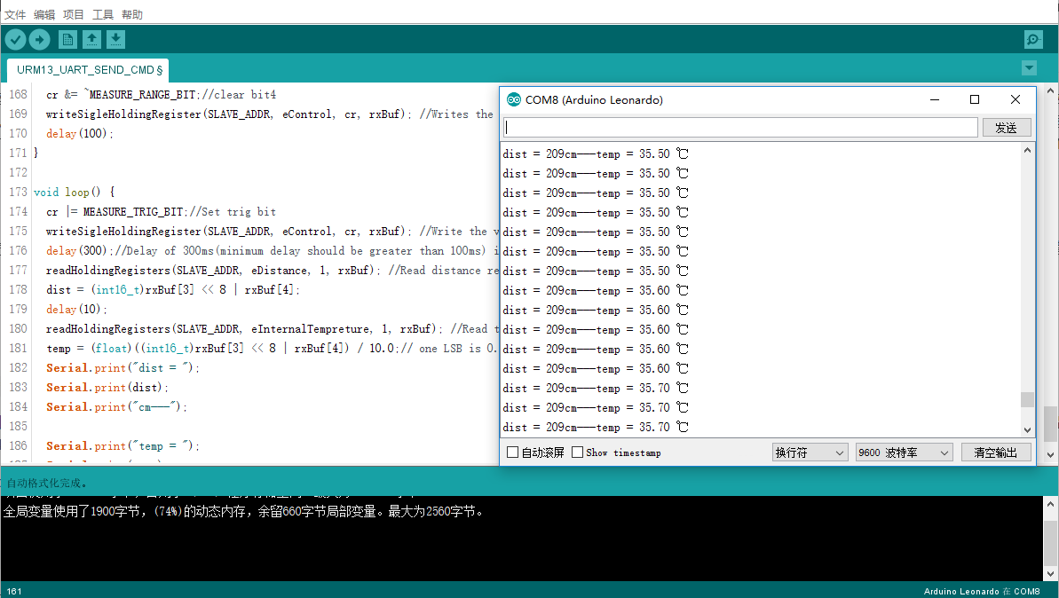
void loop() {
cr |= MEASURE_TRIG_BIT;//Set trig bit
writeSigleHoldingRegister(SLAVE_ADDR, eControl, cr, rxBuf); //Write the value to the control register and trigger a ranging
delay(300);//Delay of 300ms(minimum delay should be greater than 100ms) is to wait for the completion of ranging
readHoldingRegisters(SLAVE_ADDR, eDistance, 1, rxBuf); //Read distance register, one LSB is 1cm
dist = (int16_t)rxBuf[3] << 8 | rxBuf[4];
delay(10);
readHoldingRegisters(SLAVE_ADDR, eInternalTempreture, 1, rxBuf); //Read tempreture register
temp = (float)((int16_t)rxBuf[3] << 8 | rxBuf[4]) / 10.0;// one LSB is 0.1 ℃
Serial.print("dist = ");
Serial.print(dist);
Serial.print("cm---");
Serial.print("temp = ");
Serial.print(temp);
Serial.println(" ℃");
}
I2C寄存器说明
| 地址 | 名称 | 读写 | 数据范围 | 默认值 | 数据说明 |
|---|---|---|---|---|---|
| 0x00 | 传感器地址寄存器 | R | 0x01-0xF7 | 0x12 | I2C从机地址 断电保存,重启后生效 |
| 0x01 | 传感器PID寄存器 | R | 0x00-0xFF | 0x02 | 该位用于产品校验[可实现传感器类型的检测] |
| 0x02 | 传感器VID寄存器 | R | 0x00-0xFF | 0x10 | 固件版本号:0x10代表V1.0 |
| 0x03 0x04 |
距离值寄存器高位 距离值寄存器低位 |
R R |
0x00-0xFF 0x00-0xFF |
0xFF 0xFF |
LSB为1cm,例:0x0064 = 100cm |
| 0x05 0x06 |
板载温度值寄存器高位 板载温度值寄存器低位 |
R R |
0x00-0xFF 0x00-0xFF |
0xFF 0xFF |
LSB代表0.1摄氏度,有符号数,例:读出的高位值 TEMP_H = 0x00,低位值TEMP_L = 0xfe,则实际测得的温度值为0x00fe / 10 = 25.4℃ |
| 0x07 0x08 |
外部温度补偿数据寄存器高位 外部温度补偿数据寄存器低位 |
R/W R/W |
0x00-0xFF 0x00-0xFF |
0x00 0x00 |
写入环境温度数据到该寄存器用于外部温度补偿,LSB代表0.1摄氏度(有符号数) |
| 0x09 | 配置寄存器 | R/W | 0x00-0xFF | 0x04 | bit5-bit7:保留 bit4(最大测量距离设置位): 0:大量程测距(40 - 900cm) 1:小量程测距(15-150cm) bit3:保留 bit2: 0:自动测量模式,模块一直在进行距离测量,并不断更新距离寄存器 1:被动测量,发送一次测距命令,模块测量一次距离并将测量的距离值存入距离寄存器 bit1: 0:温度补偿开启 1:关闭温度补偿 bit0: 0:使用板载温度补偿 1:使用外部温度补偿 断电保存,立即生效 |
| 0x0A | 命令寄存器 | R/W | 0x00-0xFF | 0x00 | bit7-bit6:保留 bit0: 向该位写1,触发一次测距,向该位写0被忽略 |
| 0x0B | 电源噪声等级寄存器 | R | 0x00-0x0A | 0x00 | 0x00-0x0A对应噪声等级0-10 该参数能够反映供电电源以及环境对传感器的影响程度。噪声等级越小,传感器得到的距离值将更精准。 |
| 0x0C | 测距灵敏度设置寄存器 | R/W | 0x00-0x0A | 0x00 | 0x00-0x0A:灵敏度等级0-10 用于设置传感器大量程段(40-900cm)的测距灵敏度,该值越小,灵敏度越高 断电保存,立即生效 |
I2C模式Arduino示例
###准备
- 硬件
- 1 x Arduino Leonardo控制板
- 1 x USB数据线(USB数据线一端连接Arduino板USB口,另一端连接至电脑USB口)
- 软件
- Arduino IDE, 点击下载Arduino IDE
- 在IDE中打开Library Manager(Ctrl+Shift+I),搜索并安装DFRobot_URM13库
- 硬件接线示意图
基于库示例代码
/*!
* @file URM13WorkInIIC.ino
* @brief This demo shows how URM13 works in IIC interface mode.
* @n can obtain and change the sensor basic information, configure parameters and get the current distance value and current temperature value
* @copyright Copyright (c) 2010 DFRobot Co.Ltd (http://www.dfrobot.com)
* @license The MIT License (MIT)
* @author [qsjhyy](yihuan.huang@dfrobot.com)
* @version V1.0.0
* @date 2021-09-18
* @url https://github.com/DFRobot/DFRobot_URM13
*/
#include <DFRobot_URM13.h>
/*!
* UART(Modbus-RTU) and I2C/TRIG mode switch
* URM13 sensor default setting is in UART mode. the sensor can switch between I2C and UART modes simply by short-circuiting different pins before power-on:
* I2C/TRIG: Short-circuit TRIG and ECHO pins before the sensor is powered on. After the sensor is powered on, that the LED flashes twice indicates the sensor has switched to I2C mode.
* UART(Modbus-RTU): Short-circuit TRIG and BUSY pins before the sensor is powered on. After the sensor is powered on, that the LED flashes once indicates the sensor has switched to UART(Modbus-RTU) mode.
* After the mode switch succeeds, users can disconnect the corresponding pin short-circuiting, and the switched mode will be recorded by the sensor and take effect permanently.
*/
/*
* instantiate an object to drive the sensor;
* need to set the sensor IIC address and the IIC bus used by it, keep the default value if it’s not changed.
*/
DFRobot_URM13_IIC sensor(/*iicAddr = */0x12, /*iicBus = */&Wire);
// open the macro if you want to use data measuring completion signal from busyPin as a measure, note: use pin numbers based on the main controller settings using
// #define BUSYPIN_SIGNAL
#ifdef BUSYPIN_SIGNAL
int16_t busyPin = 4; // "Data Measuring Ready Signal" pin, you can set the pins can be used as required (depending on the controller differences)
#define isSensorBusy() (digitalRead(busyPin))
#endif
void setup()
{
Serial.begin(115200);
#ifdef BUSYPIN_SIGNAL
pinMode(busyPin, INPUT); // initialize "Data Measuring Ready Signal" pin to input
#endif
// initialize the sensor
while( NO_ERR != sensor.begin() ){
Serial.println("Communication with device failed, please check connection");
delay(3000);
}
Serial.println("Begin ok!");
/**
* retrieve basic information from the sensor and buffer it into basicInfoIIC, the structure that stores information
*/
sensor.refreshBasicInfo();
/* I2C slave address of the module, default value is 0x12, module device address(1~127) */
Serial.print("mailing address: 0x");
Serial.println(sensor.basicInfoIIC.addr, HEX);
/* module PID, default value is 0x02 the bit is used for product check[can detect the sensor type] */
Serial.print("PID: 0x0");
Serial.println(sensor.basicInfoIIC.PID, HEX);
/* module VID, firmware revision number:0x10 represents V1.0 */
Serial.print("VID: 0x");
Serial.println(sensor.basicInfoIIC.VID, HEX);
/**
* set the module communication address, power off to save the settings, and restart for the settings to take effect
* addr device address to be set, IIC address range(1~127 is 0x01~0x7F)
*/
sensor.setADDR(0x12);
/**
* set measure mode
* mode measure mode to be set, the following patterns constitute mode:
* eInternalTemp: use internal temperature compensation function, eExternalTemp: use external temperature compensation function (users need to write external temperature)
* eTempCompModeEn: enable temperature compensation function, eTempCompModeDis: disable temperature compensation function
* eAutoMeasureModeEn: automatic ranging, eAutoMeasureModeDis: passive ranging
* eMeasureRangeModeLong: large range measurement(40 - 900cm), eMeasureRangeModeShort: small range measurement(15-150cm)
*/
sensor.setMeasureMode(sensor.eInternalTemp | \
sensor.eTempCompModeEn | \
sensor.eAutoMeasureModeDis | \
sensor.eMeasureRangeModeLong);
/**
* note: the api makes external temperature compensation function meaningful only when setting measure mode
* write ambient temperature data for external temperature compensation, the setting is invalid when out of range
* temp written ambient temperature data, unit is ℃, resolution is 0.1℃, signed number, range:-10℃~+70℃
*/
sensor.setExternalTempretureC(30.0);
/**
* ranging sensitivity setting, 0x00-0x0A:sensitivity level 0-10
* mode to set the sensor ranging sensitivity in large range (40-900cm), the smaller the value, and the higher the sensitivity, power off to save the settings, and it takes effect at once
*/
sensor.setMeasureSensitivity(0x00);
Serial.println();
delay(1000);
}
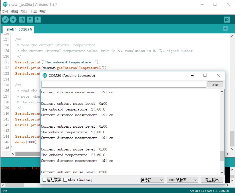
void loop()
{
/**
* the function to trigger measuring in passive measurement mode
* in passive measurement mode, the function is called once, the ranging command is sent once, and the module measures the distance once and saves the measured value into the distance register
*/
sensor.passiveMeasurementTRIG();
#ifdef BUSYPIN_SIGNAL
// You can replace the delay with these two lines of code
while(isSensorBusy()== HIGH); // Wait for the sensor to start ranging
while(isSensorBusy()== LOW); // Wait for sensor ranging to complete
#else
delay(100); // delay 100ms
#endif
/**
* get noise level of power supply, the smaller the noise level, the more accurate the distance value obtained by the sensor
* the parameter indicates the influence of power supply and environment on the sensor. 0x00-0x0A matches noise level of 0-10。
*/
Serial.print("Current ambient noise level: 0x0");
Serial.println(sensor.getNoiseLevel(), HEX);
/**
* read the current internal temperature
* the current internal temperature value, unit is ℃, resolution is 0.1℃, signed number
*/
Serial.print("The onboard temperature: ");
Serial.print(sensor.getInternalTempretureC());
Serial.println(" C");
/**
* read the current distance value, the value of zero indicates it’s not measured within the range
* note: when the object is not in the sensor ranging range, the read measured data will be meaningless
* the current distance value, unit is cm, large range(40 - 900cm)small range(15-150cm)
*/
Serial.print("Current distance measurement: ");
Serial.print(sensor.getDistanceCm());
Serial.println(" cm");
Serial.println();
delay(1000);
}
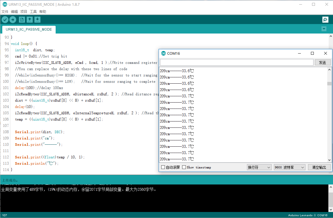
基于I2C接口读写寄存器示例代码
/*!
       Download this demo to test config to URM13, connect sensor through IIC interface
       Data will print on your serial monitor

       This example is the ultrasonic passive measurement distance and the temperature of the module.

       Copyright   [DFRobot](http://www.dfrobot.com), 2018
       Copyright   GNU Lesser General Public License

       version  V1.0
       date  21/08/2020
*/
#include <Wire.h>
typedef enum {
  eAddr = 0,
  ePid,
  eVid,
  eDistanceH ,
  eDistanceL,
  eInternalTempretureH,
  eInternalTempretureL,
  eExternalTempretureH,
  eExternalTempretureL,
  eConfig,
  eCmd,
  eNoise,
  eSensitivity,
  eRegNum
} regindexTypedef;

#define    MEASURE_RANGE_BIT        ((uint8_t)0x01 << 4)
#define    MEASURE_MODE_BIT         ((uint8_t)0x01 << 2)
#define    TEMP_CPT_ENABLE_BIT      ((uint8_t)0x01 << 1)
#define    TEMP_CPT_SEL_BIT         ((uint8_t)0x01 << 0)

#define    IIC_SLAVE_ADDR           ((uint8_t)0x12)
#define    isSensorBusy()           (digitalRead(busyPin))

int16_t    busyPin = 4;
/*
  @brief Write data to register of client

  @param addr : Address of Client
  @param regIndex: Reg index
  @param pDataBuf: point to data buffer
  @param dataLen: data length
*/
void i2cWriteBytes(uint8_t addr, regindexTypedef regIndex , uint8_t *pDataBuf, uint8_t dataLen )
{
  Wire.beginTransmission(addr); // transmit to device
  Wire.write(regIndex);              // sends one byte
  for (uint8_t i = 0; i < dataLen; i++) {
    Wire.write(*pDataBuf);
    pDataBuf++;
  }
  Wire.endTransmission();    // stop transmitting
}
/*
  @brief Read data from register of client

  @param addr : Address of Client
  @param regIndex: Reg index
  @param pDataBuf: point to data buffer
  @param dataLen: data length
*/
void i2cReadBytes(uint8_t addr, regindexTypedef regIndex , uint8_t *pDataBuf, uint8_t dataLen )
{
  unsigned char i = 0;
  Wire.beginTransmission(addr); // transmit to device #8
  Wire.write(regIndex);              // sends one byte
  Wire.endTransmission();    // stop transmitting
  Wire.requestFrom(addr, dataLen);
  while (Wire.available()) {  // slave may send less than requested
    pDataBuf[i] = Wire.read();
    i++;
  }
}

uint8_t cfg = 0, cmd = 0;
uint8_t rxBuf[100] = {0};
void setup() {
  Wire.begin(); // join i2c bus (address optional for master)
  Serial.begin(9600); // join i2c bus (address optional for master)
  pinMode(busyPin, INPUT);
  cfg &= ~MEASURE_RANGE_BIT;//clear bit4,long-range ranging mode
  //cfg |= MEASURE_RANGE_BIT;//set bit4,short-range ranging mode
  cfg |=  MEASURE_MODE_BIT;//Set bit2,i2c passive mode
  //cfg &= ~MEASURE_MODE_BIT;//clear bit2 , set to Automatic ranging mode
  cfg &= ~TEMP_CPT_ENABLE_BIT;//clear bit1,enable temperature compensation
  //cfg |= TEMP_CPT_ENABLE_BIT;//set bit1,disable temperature compensation
  cfg &= ~TEMP_CPT_SEL_BIT;//clear bit0,select internal temperature compensation
  //cfg |= TEMP_CPT_SEL_BIT;//set bit0,select external temperature compensation
  i2cWriteBytes(IIC_SLAVE_ADDR, eConfig , &cfg, 1 );
  delay(100);
}
void loop() {
  int16_t  dist, temp;
  cmd |= 0x01;//Set trig bit
  i2cWriteBytes(IIC_SLAVE_ADDR, eCmd , &cmd, 1 );//Write command register
  //You can replace the delay with these two lines of code
  //while(isSensorBusy()== HIGH);  //Wait for the sensor to start ranging
  //while(isSensorBusy()== LOW);   //Wait for sensor ranging to complete
  delay(100);//delay 100ms
  i2cReadBytes(IIC_SLAVE_ADDR, eDistanceH, rxBuf, 2 ); //Read distance register
  dist = ((uint16_t)rxBuf[0] << 8) + rxBuf[1];
  delay(10);
  i2cReadBytes(IIC_SLAVE_ADDR, eInternalTempretureH, rxBuf, 2 ); //Read the onboard temperature register
  temp = ((uint16_t)rxBuf[0] << 8) + rxBuf[1];

  Serial.print(dist, DEC);
  Serial.print("cm");
  Serial.print("------");

  Serial.print((float)temp / 10, 1);
  Serial.println("℃");
}
树莓派驱动库使用方法
镜像烧入
1.点击烧录系统详细操作步骤 。
远程连接(若不需要远程连接,有相关外围设备(屏幕键盘等)直接操作树莓派,则跳过此步骤。)
1.烧录系统详细操作步骤中:树莓派远程连接教程。如果有树莓派屏幕,那么应该可以轻松配置wifi连接并查看IP。没有屏幕也可通过我们官方wiki的图文流程学会如何连接wifi并查看IP。最后通过树莓派IP和完成远程连接,进入树莓派后台。
安装驱动
1.配置启动树莓派的I2C、UART接口。如已开启,可跳过该步骤。
- 打开终端(Terminal),键入如下指令,并回车:
pi@raspberrypi:~ $ sudo raspi-config
然后用上下键选择3 Interfacing Options, 按回车进入,选择P5 I2C, 按回车确认YES即设置I2C使能。 - 再次用上下键选择
3 Interfacing Options, 按回车进入,选择P6 Serial Port, 按回车确认YES即设置Serial Port使能。 - 最后重启树莓派主控板,使前面的使能配置生效:
pi@raspberrypi:~ $ sudo reboot
modbus使用的UART还需要额外配置一下,不然很可能通信不成功,可以作如下配置:
-
查看串口
pi@raspberrypi:~ $ ls -l /dev
在没有配置过正常情况下看到的应该是:
没有serial0,只有 serial1 -> ttyAMA0,启动串口(这一步我们前面通过raspi-config已经配置了)。pi@raspberrypi:~ $ sudo vi /boot/config.txt在打开的文件后面添加:
#ENABLE UART
enable_uart=1
然后需要重启pi@raspberrypi:~ $ sudo reboot
在设置中启用串口后,会发现 /dev目录下变成了两个:
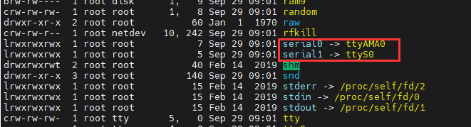
-
禁用蓝牙(硬件串口与mini串口默认映射对换)
pi@raspberrypi:~ $ sudo vi /boot/config.txt在打开的文件后面添加:
dtoverlay=pi3-disable-bt修改后需要重启:pi@raspberrypi:~ $ sudo reboot(因为蓝牙也使用硬件串口,所以我们在 /boot/config.txt里面加上 dtoverlay=pi3-disable-bt ,ttyAMA0 得以释放,这时候树莓派也自动交换了ttyAMA0和ttyS0,把serial0 分配给了 ttyAMA0 。)
-
禁用串口的控制台功能,前面的步骤已经交换了硬件串口与mini串口的映射关系,但现在想使用树莓派外接串口模块进行通信还不行,因为树莓派IO引出的串口默认是用来做控制台使用的,它的初衷是为了在没有网络接口时,通过串口对树莓派进行相关的配置。因此需要禁用这个默认功能,使得串口为我们自由使用。在树莓派命令窗口中分别通过如下两个命令停止和禁用串口的控制台功能。由于我们前面已经交换了串口的映射关系,因此这里注意是ttyAMA0。
pi@raspberrypi:~ $ sudo systemctl stop serial-getty@ttyAMA0.service
pi@raspberrypi:~ $ sudo systemctl disable serial-getty@ttyAMA0.service
最后还需要删除一个东西:
pi@raspberrypi:~ $ sudo vi /boot/cmdline.txt
在打开的文件中删去 :console=serial0,115200
2.安装Python依赖库与git,树莓派需要联网。如已安装,可跳过该步骤。 -
在终端中,依次键入如下指令(更新所有东西;安装 build-essential、python-dev、python-smbus、git),并回车:
pi@raspberrypi:~ $ sudo apt-get update
pi@raspberrypi:~ $ sudo apt-get install build-essential python-dev python-smbus git
3.下载URM13驱动库及其依赖库。 -
在终端中,依次键入如下指令(安装modbus_tk库;切换文件目录到桌面;用git克隆下载驱动库到树莓派上),并回车:
使用python2则这样安装:pi@raspberrypi:~ $ pip install modbus_tk
使用python3则这样安装:pi@raspberrypi:~ $ pip3 install modbus_tk
pi@raspberrypi:~ $ cd Desktop/
pi@raspberrypi:~/Desktop $ git clone https://github.com/cdjq/DFRobot_URM13
运行示例代码
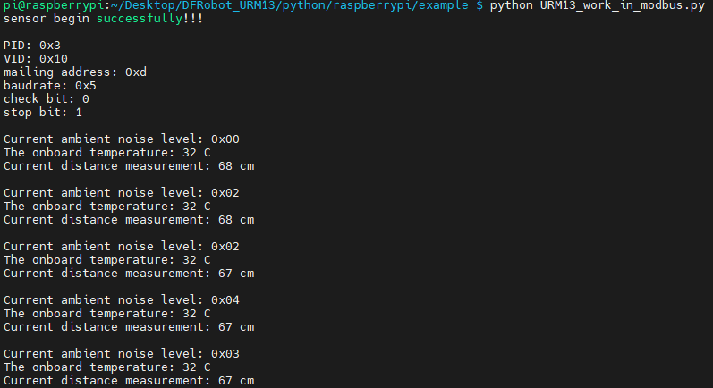
1.modbus接口测距示例(URM13_work_in_modbus.py)
- 在终端中,键入如下指令并回车,运行样例代码:
pi@raspberrypi:~/Desktop $ cd DFRobot_URM13/python/raspberrypi/example
pi@raspberrypi:~/Desktop/DFRobot_URM13/python/raspberrypi/example $ python URM13_work_in_modbus.py - 运行结果
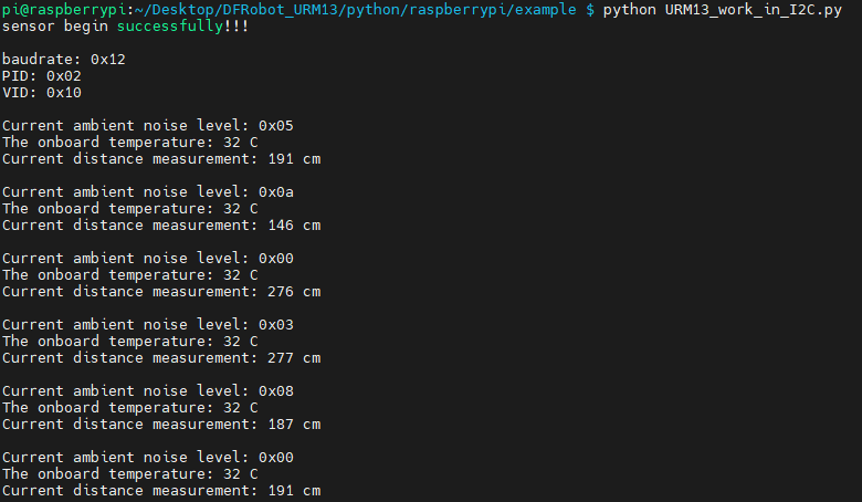
2.I2C接口测距示例(URM13_work_in_I2C.py) - 在终端中,键入如下指令并回车,运行样例代码:
pi@raspberrypi:~/Desktop $ cd DFRobot_URM13/python/raspberrypi/example
pi@raspberrypi:~/Desktop/DFRobot_URM13/python/raspberrypi/example $ python URM13_work_in_I2C.py - 运行结果
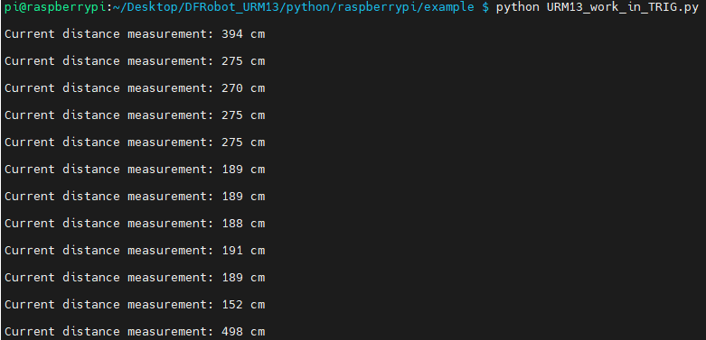
3.TRIG接口测距示例(URM13_work_in_TRIG.py) - 在终端中,键入如下指令并回车,运行样例代码:
pi@raspberrypi:~/Desktop $ cd DFRobot_URM13/python/raspberrypi/example
pi@raspberrypi:~/Desktop/DFRobot_URM13/python/raspberrypi/example $ python URM13_work_in_TRIG.py - 运行结果
探测角度及灵敏度说明
超声波传感器的物理特性决定了其实际具有不规则的探测区域,因此超声波测距传感器的探测角度难以被准确的定义。我们分别使用了2种参考目标障碍物对多样本产品进行了测试,对应目标的参照检测区域如下图示:
常见问题
1、如有疑问,欢迎通过qq或者论坛联系我们!
更多问题及有趣的应用,可以 访问论坛 进行查阅或发帖。
