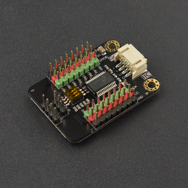
简介
这是一款16位数字IO口扩展板,通过I2C接口与主控通信,可以读取并设置引脚的电平值。支持8个I2C地址,一块主控上最多并联8个模块,一次最多扩展128个IO口。该款I2C转16位数字IO扩展板有2组IO引脚, 分别为GPIOA组和GPIOB组,每组有8位独立IO口,共16位,且每个IO口都可独立被设置为输入、输出、上拉输入(内部接100KΩ上拉电阻)、或中断等IO模式。此外,该模块还有2个中断信号引脚IA和IB, 其中IA用于检测GPIOA组的IO口是否发生中断、IB用于检测GPIOB组的IO口是否发生中断,当GPIOA或GPIOB中某个引脚发生中断,则相应的IA或IB会产生一个高电平信号。
应用场景
- 机器人
- 互动媒体
- 光立方
技术规格
- 接口供电电压:3.3V-5.5V
- I2C地址:0x20~0x27
- Digital I/O 数字输入/输出端: PA0~PA7,PB0~PB7
- IO口驱动电流: 20mA
- 中断信号引脚:IA、IB
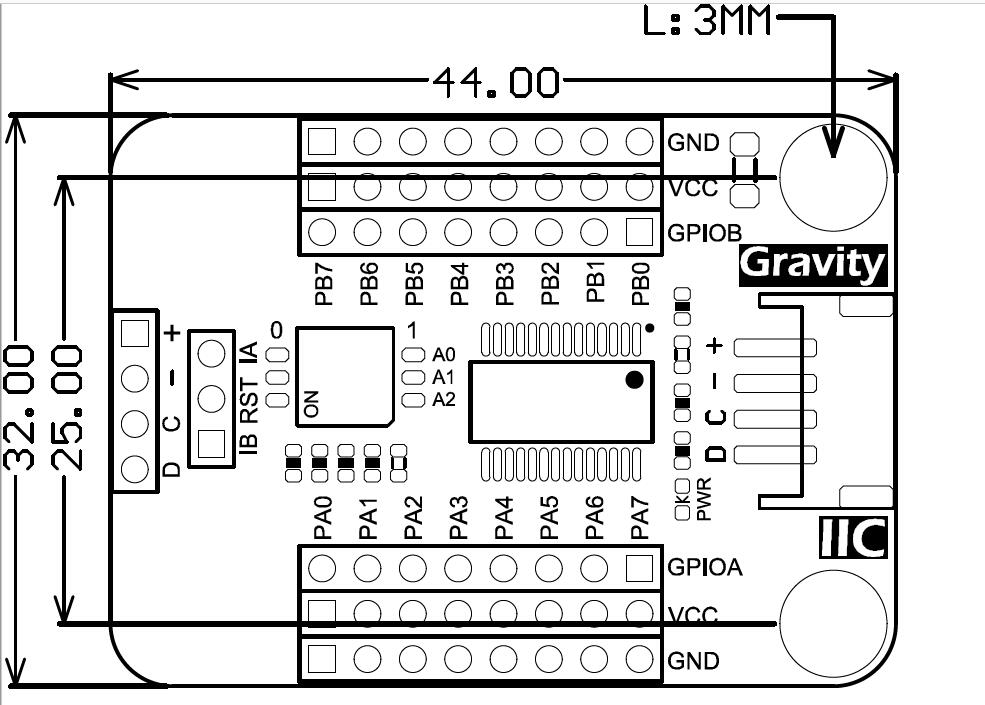
- 产品尺寸:44*32mm
引脚说明
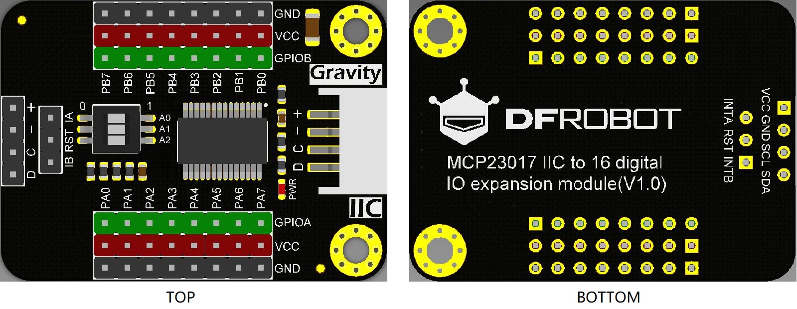
引脚说明
| 标号 | 名称 | 功能描述 |
|---|---|---|
| 1 | +/VCC | 电源正极 |
| 2 | -/GND | 电源负极 |
| 3 | C | I2C时钟线 |
| 4 | D | I2C数据线 |
| 5 | RST | 复位引脚 |
| 6 | IA | GPIOA中断检测引脚 |
| 5 | IB | GPIOB中断检测引脚 |
| 6 | PWR | 电源指示灯 |
| 7 | A0/A1/A2 | I2C地址切换开关 |
数字IO口简介表
| GPIOA | 0 | 1 | 2 | 3 | 4 | 5 | 6 | 7 |
|---|---|---|---|---|---|---|---|---|
| PA0 | PA1 | PA2 | PA3 | PA4 | PA5 | PA6 | PA7 | |
| GPIOB | 8 | 9 | 10 | 11 | 12 | 13 | 14 | 15 |
| PB0 | PB1 | PB2 | PB3 | PB4 | PB5 | PB6 | PB7 |
上表中的每个数字引脚,都可被设置为输入、输出、上拉输入、中断等引脚模式。
使用教程
准备
- 硬件
- 1 x Arduino UNO控制板
- 1 x MCP23017 I2C to 16 digital IO expansion module
- 若干 按钮
- 若干 LED灯
- 软件
- Arduino IDE, 点击下载Arduino IDE
- 点击下载库文件和示例程序
关于如何安装库文件,点击链接
- 主要API接口函数列表
  /**
   *@功能 枚举IO口分组
   */
  typedef enum{
      eGPIOA = 1,  /**< GPIO Group A*/
      eGPIOB = 2,  /**< GPIO Group B*/
      eGPIOALL = 3 /**< GPIO Group A+B*/
  }eGPIOGrout_t;

  /**
   *@功能 枚举所有引脚
   */
  typedef enum{
      eGPA0 = 0,  /**< PortA, digital pin GPA0*/
      eGPA1,  /**< PortA, digital pin GPA1*/
      eGPA2,  /**< PortA, digital pin GPA2*/
      eGPA3,  /**< PortA, digital pin GPA3*/
      eGPA4,  /**< PortA, digital pin GPA4*/
      eGPA5,  /**< PortA, digital pin GPA5*/
      eGPA6,  /**< PortA, digital pin GPA6*/
      eGPA7,  /**< PortA, digital pin GPA7*/
      eGPB0,  /**< PortB, digital pin GPB0*/
      eGPB1,  /**< PortB, digital pin GPB1*/
      eGPB2,  /**< PortB, digital pin GPB2*/
      eGPB3,  /**< PortB, digital pin GPB3*/
      eGPB4,  /**< PortB, digital pin GPB4*/
      eGPB5,  /**< PortB, digital pin GPB5*/
      eGPB6,  /**< PortB, digital pin GPB6*/
      eGPB7,  /**< PortB, digital pin GPB7*/
      eGPIOTotal
  }ePin_t;

  /**
   *@功能 枚举中断触发模式
   */
  typedef enum{
      eLowLevel = 0,   /*低电平中断 */
      eHighLevel,      /*高电平中断*/
      eRising,         /*上升沿中断*/
      eFalling,        /*下降沿中断*/
      eChangeLevel     /*双边沿中断*/
  }eInterruptMode_t;

  /**
   * @功能 构造函数
   * @参数 pWire I2C总线指针对象。在调用函数时,可以将参数传递给它。
   * @参数 8位I2C地址,范围为0x20~0x27。通过DIP开关改变A2A1A0,修改I2C地址。在调用函数时,设置I2C地址。(默认值:0x27)
   * 0  0  1  0  | 0  A2 A1 A0
     0  0  1  0  | 0  1  1  1    0x27
     0  0  1  0  | 0  1  1  0    0x26
     0  0  1  0  | 0  1  0  1    0x25
     0  0  1  0  | 0  1  0  0    0x24
     0  0  1  0  | 0  0  1  1    0x23
     0  0  1  0  | 0  0  1  0    0x22
     0  0  1  0  | 0  0  0  1    0x21
     0  0  1  0  | 0  0  0  0    0x20
   */
  DFRobot_MCP23017(TwoWire &wire = Wire, uint8_t addr = 0x27);
  ~DFRobot_MCP23017();

  /**
   * @功能 设置引脚模式,可设置为输入、输出或上拉输入100 kΩ(内部上拉电阻)
   * @参数 引脚号,可以是ePin_t中包含的所有枚举值(eGPA0-eGPB7/ 0-15)。
   * @参数 模式, 可以是 INPUT, OUTPUT, INPUT_PULLUP
   * @返回 如果设置成功,则返回0,否则返回非0。
   */
  int pinMode(ePin_t pin, uint8_t mode);

  /**
   * @功能 写数字引脚。写之前需要将引脚设置为输出模式。
   * @参数 引脚号,可以是ePin_t中包含的所有枚举值(eGPA0-eGPB7/ 0-15)。
   * @参数 高低电平 1(HIGH)或0(LOW)
   * @返回 如果写入成功,则返回0,否则返回非0。
   */
  int digitalWrite(ePin_t pin, uint8_t level);

  /**
   * @功能 读引脚。读取之前需要将pin设置为输入模式。
   * @参数 引脚号,可以是ePin_t中包含的所有枚举值(eGPA0-eGPB7/ 0-15)。
   * @返回 返回高低电平
   */
  int digitalRead(ePin_t pin);

  /**
   * @功能 设置一个引脚为中断模式
   * @参数 引脚号,可以是ePin_t中包含的所有枚举值(eGPA0-eGPB7/ 0-15)。
   * @参数 中断模式:eInterruptMode_t中包含的所有枚举值。
   * @参数 中断服务函数,需要用户定义和传递参数。函数原型: void func(int)
   */
  void pinModeInterrupt(ePin_t pin, eInterruptMode_t mode,  MCP23017_INT_CB cb);

  /**
   * @功能 轮询某组端口是否发生中断
   * @参数 group 端口组,可填eGPIOGrout_t包含的所有枚举值GPIO A组(eGPIOA)、GPIO B组(eGPIOB)A+B组(eGPIOALL)
   * @n 填eGPIOA,则轮询A组端口是否发生中断
   * @n 填eGPIOB,则轮询B组端口是否发生中断
   * @n 填eGPIOALL,则轮询A组和B组端口是否发生中断
   * @n 不填,默认轮询A组和B组所有端口是否发生中断
   */
  void pollInterrupts(eGPIOGrout_t group=eGPIOALL);

  /**
   * @功能 将引脚转为字符串描述
   * @参数 引脚号,可以是ePin_t中包含的所有枚举值(eGPA0-eGPB7/ 0-15)。
   * @返回 返回引脚描述字符串
   * @n 如"GPIOA0" "GPIOA1" "GPIOA2" "GPIOA3" "GPIOA4" "GPIOA5" "GPIOA6" "GPIOA7"
   * @n   "GPIOB0" "GPIOB1" "GPIOB2" "GPIOB3" "GPIOB4" "GPIOB5" "GPIOB6" "GPIOB7"
   */
  String pinDescription(ePin_t pin);

  /**
   * @功能 将引脚转为字符串描述
   * @参数 引脚号,范围0-15
   * @返回 返回引脚描述字符串
   * @n 如"GPIOA0" "GPIOA1" "GPIOA2" "GPIOA3" "GPIOA4" "GPIOA5" "GPIOA6" "GPIOA7"
   * @n   "GPIOB0" "GPIOB1" "GPIOB2" "GPIOB3" "GPIOB4" "GPIOB5" "GPIOB6" "GPIOB7"
   */
   String pinDescription(int pin);
拨码开关与I2C地址关系
拨码开关配置与I2IC地址的对应关系
| A2 | A1 | A0 | addr |
|---|---|---|---|
| 0 | 0 | 0 | 0x20 |
| 0 | 0 | 1 | 0x21 |
| 0 | 1 | 0 | 0x22 |
| 0 | 1 | 1 | 0x23 |
| 1 | 0 | 0 | 0x24 |
| 1 | 0 | 1 | 0x25 |
| 1 | 1 | 0 | 0x26 |
| 1 | 1 | 1 | 0x27(默认) |
接线图

样例代码1 - 按钮输入
将IO扩展板的PA0引脚设置为输入模式,并接上按钮,当按钮被按下时,串口打印字符串"Button press!";
/*!
 * @file buttonInput.ino
 * @brief Connect a button to the IO expansion board, set a pin of the board(eg: eGPA0) to input mode to detect the button status.
 * @n Experiment phenomenon: connect a button on a pin of the IO board(eg:eGPA0), detect the level of the pin and print out
 * @n the button status on serial port.
 *
 * @copyright   Copyright (c) 2010 DFRobot Co.Ltd (https://www.dfrobot.com)
 * @licence     The MIT License (MIT)
 * @author [Arya](xue.peng@dfrobot.com)
 * @version  V1.0
 * @date  2019-07-18
 * @get from https://www.dfrobot.com
 * @url https://github.com/DFRobot/DFRobot_MCP23017
 */
#include <DFRobot_MCP23017.h>
/*DFRobot_MCP23017 constructor
 *Parameter&wire Wire
 *Parameter addr  I2C address can be select from 0x20~0x27; the relationship of DIP switch(A2, A1, A0) and I2C address(0x27) is
 *shown below:
  * 0  0  1  0  | 0  A2 A1 A0
    0  0  1  0  | 0  1  1  1    0x27
    0  0  1  0  | 0  1  1  0    0x26
    0  0  1  0  | 0  1  0  1    0x25
    0  0  1  0  | 0  1  0  0    0x24
    0  0  1  0  | 0  0  1  1    0x23
    0  0  1  0  | 0  0  1  0    0x22
    0  0  1  0  | 0  0  0  1    0x21
    0  0  1  0  | 0  0  0  0    0x20
 */
DFRobot_MCP23017 mcp(Wire, /*addr =*/0x27);//constructor, change the Level of A2, A1, A0 via DIP switch to revise the I2C address within 0x20~0x27.
//DFRobot_MCP23017 mcp;//use default parameter, Wire  0x27(default I2C address)

//Prepare: connect a button to a digital pin of the IO expansion board(eg: eGPA0)
void setup() {
  Serial.begin(115200);
  /*wait for the chip to be initialized completely, and then exit*/
  while(mcp.begin() != 0){
    Serial.println("Initialization of the chip failed, please confirm that the chip connection is correct!");
    delay(1000);
  }
  /*pinMode function is used to set the pin mode of module
  Parameter pin, the available parameter is shown below:
  eGPA0  eGPA1  eGPA2  eGPA3  eGPA4  eGPA5  eGPA6  eGPA7  eGPA
   0       1      2      3      4      5      6      7
  eGPB0  eGPB1  eGPB2  eGPB3  eGPB4  eGPB5  eGPB6  eGPB7  eGPB
   8       9      10     11     12     13     14     15
  Parameter mode, can be set to: INPUT, OUTPUT, INPUT_PULLUP(internal 100KΩ pull-up resistor)
  */
  mcp.pinMode(/*pin = */mcp.eGPA0, /*mode = */INPUT);
  /*Set all Group GPIOA pins to input*/
  //mcp.pinMode(/*pin = */mcp.eGPA, /*mode = */INPUT);
}

void loop() {
  /*digitalRead function is used to read the Level of a digital pin. The pin needs to be set to input mode before using this function.
  Parameter pin, the available parameter is shown below:
  eGPA0  eGPA1  eGPA2  eGPA3  eGPA4  eGPA5  eGPA6  eGPA7  eGPA
   0       1      2      3      4      5      6      7
  eGPB0  eGPB1  eGPB2  eGPB3  eGPB4  eGPB5  eGPB6  eGPB7  eGPB
   8       9      10     11     12     13     14     15
  */
  uint8_t value = mcp.digitalRead(/*pin = */mcp.eGPA0);
  /*Read  level of Group GPIOA pins*/
  //value = mcp.digitalRead(/*pin = */mcp.eGPA);
  if(value){
      Serial.println("Button press!");
      delay(200);
  }else{
      //Serial.println("Button release!");
  }
}
结果
当按下PA0引脚上接的按钮时,串口打印"Button press!",如下图所示:

样例代码2 - 引脚输出
将扩展板的PA7设置为输出模式,并接上LED灯,实现1s内LED灯状态切换.
/*!
 * @file ledOutput.ino
 * @brief Set a pin of IO expansion board(eg:eGPA7) to output mode, and output High/Low.
 * @n Experiment phenomenon: the LED connected to the pin of IO board(eg:eGPA7) repeatedly lights up for 1s and turns off 1s.
 *
 * @copyright   Copyright (c) 2010 DFRobot Co.Ltd (https://www.dfrobot.com)
 * @licence     The MIT License (MIT)
 * @author [Arya](xue.peng@dfrobot.com)
 * @version  V1.0
 * @eGPAte  2019-07-18
 * @get from https://www.dfrobot.com
 * @url https://github.com/DFRobot/DFRobot_MCP23017
 */

#include <DFRobot_MCP23017.h>
/*DFRobot_MCP23017 Constructor
 *Parameter &wire  Wire
 *Parameter addr  I2C address can be selected from 0x20~0x27, the relationship of DIP switch (A2,A1,A0) and I2C address (0x27)is shown below:
  * 0  0  1  0  | 0  A2 A1 A0
    0  0  1  0  | 0  1  1  1    0x27
    0  0  1  0  | 0  1  1  0    0x26
    0  0  1  0  | 0  1  0  1    0x25
    0  0  1  0  | 0  1  0  0    0x24
    0  0  1  0  | 0  0  1  1    0x23
    0  0  1  0  | 0  0  1  0    0x22
    0  0  1  0  | 0  0  0  1    0x21
    0  0  1  0  | 0  0  0  0    0x20
 */
DFRobot_MCP23017 mcp(Wire, /*addr =*/0x27);//constructor, change the Level of A2, A1, A0 via DIP switch to revise I2C address within 0x20~0x27
//DFRobot_MCP23017 mcp;//use default parameter, Wire  0x27(default I2C address)

//Prepare: connect the LED to a digital pin of IO expansion board(eg:eGPA7)
void setup(void)
{
  Serial.begin(115200);
  /*wait for the chip to be initialized completely, and then exit*/
  while(mcp.begin() != 0){
    Serial.println("Initialization of the chip failed, please confirm that the chip connection is correct!");
    delay(1000);
  }
  /*pinMode function is used to set the pin mode of the module
  Parameter pin, the available parameter is shown below:
  eGPA0  eGPA1  eGPA2  eGPA3  eGPA4  eGPA5  eGPA6  eGPA7  eGPA
   0       1      2      3      4      5      6      7
  eGPB0  eGPB1  eGPB2  eGPB3  eGPB4  eGPB5  eGPB6  eGPB7  eGPB
   8       9      10     11     12     13     14     15
  Parameter mode, can be set to: INPUT, OUTPUT, INPUT_PULLUP mode (internal 100KΩ pull-up resistor)
  */
  mcp.pinMode(/*pin = */mcp.eGPA7, /*mode = */OUTPUT);
  /*Set all Group GPIOA pins to output*/
  //mcp.pinMode(/*pin = */mcp.eGPA, /*mode = */OUTPUT);
}

void loop(void)
{
  Serial.println("Pin output high level!");
  /*digitalWrite function is used to make the pin output HIGH or LOW. The pin needs to be set to output mode before using this function.
  Designate a pin on the IO expansion board; parameter pin, the available parameter is shown below:
  eGPA0  eGPA1  eGPA2  eGPA3  eGPA4  eGPA5  eGPA6  eGPA7  eGPA
   0       1      2      3      4      5      6      7
  eGPB0  eGPB1  eGPB2  eGPB3  eGPB4  eGPB5  eGPB6  eGPB7  eGPB
   8       9      10     11     12     13     14     15
  */
  mcp.digitalWrite(/*pin = */mcp.eGPA7, /*level = */HIGH);
  /*Set GPIOIA0-GPIOIA3 to low and GPIOIA4-GPIOIA7 to high*/
  //mcp.digitalWrite(/*pin = */mcp.eGPA, /*Port Value = */0xF0);
  delay(1000);
  Serial.println("Pin output low level!");
  mcp.digitalWrite(/*pin = */mcp.eGPA7, /*level = */LOW);
  /*Set GPIOIA0-GPIOIA3 to high and GPIOIA4-GPIOIA7 to low*/
  //mcp.digitalWrite(/*pin = */mcp.eGPA, /*Port Value = */0x0F);
  delay(1000);
}
结果
连接到PA7上的LED灯,1s亮1s灭以此循环,并串口打印IO口PA7输出电平的状态,如下图所示:

样例代码3 - 查询中断
将数字IO口的引脚设置为中断模式,如双边沿跳变中断(eChangeLevel),下降沿中断( eFalling )、上升沿中断(eRising)、高电平中断(eHighLevel)、低电平中断(eLowLevel)等模式。 将PA0、PA1、PB6、PB7分别设置为双边沿跳变中断,下降沿中断,上升沿中断、高电平中断,并接上按钮,轮询并串口打印发生中断的引脚。
/*!
 * @file pollInterrupt.ino
 * @brief Set a pin of IO expansion board to interrupt mode, poll if there is an interrupt occurring on the pins of the port.
 * @n Experiment phenomenon: poll if there is an interrupt occurring on the port group(A, B, A+B), if there is, serial print the pin
 * @n which is interrupted.
 *
 * @copyright   Copyright (c) 2010 DFRobot Co.Ltd (https://www.dfrobot.com)
 * @licence     The MIT License (MIT)
 * @author [Arya](xue.peng@dfrobot.com)
 * @version  V1.0
 * @date  2019-07-18
 * @get from https://www.dfrobot.com
 * @url https://github.com/DFRobot/DFRobot_MCP23017
 */
#include <DFRobot_MCP23017.h>
/*DFRobot_MCP23017 Constructor
 *Parameter &wire  Wire
 *Parameter addr  I2C address can be selected from 0x20~0x27, the relationship of DIP switch (A2,A1,A0) and I2C address (0x27)
 *is shown below:
  * 0  0  1  0  | 0  A2 A1 A0
    0  0  1  0  | 0  1  1  1    0x27
    0  0  1  0  | 0  1  1  0    0x26
    0  0  1  0  | 0  1  0  1    0x25
    0  0  1  0  | 0  1  0  0    0x24
    0  0  1  0  | 0  0  1  1    0x23
    0  0  1  0  | 0  0  1  0    0x22
    0  0  1  0  | 0  0  0  1    0x21
    0  0  1  0  | 0  0  0  0    0x20
 */
DFRobot_MCP23017 mcp(Wire, 0x27);//constructor, change the Level of A2, A1, A0 via DIP switch to revise I2C address within 0x20~0x27.
//DFRobot_MCP23017 mcp;//use default parameter, Wire  0x27(default I2C address)

/*Interrupt service function, prototype void func(int index), index: the number of the pin that is interrupted*/
void func(int index){
  /*pinDescription function is used to convert a pin into string description
  Parameter pin, the available parameter is shown below:
  eGPA0  eGPA1  eGPA2  eGPA3  eGPA4  eGPA5  eGPA6  eGPA7  eGPA
   0       1      2      3      4      5      6      7
  eGPB0  eGPB1  eGPB2  eGPB3  eGPB4  eGPB5  eGPB6  eGPB7  eGPB
   8       9      10     11     12     13     14     15
  */
  String description = mcp.pinDescription(/*pin = */index);
  Serial.print(description);
  Serial.println(" Interruption occurs!");
}

void setup() {
  Serial.begin(115200);

  /*wait for the chip to be initialized completely, and then exit*/
  while(mcp.begin() != 0){
    Serial.println("Initialization of the chip failed, please confirm that the chip connection is correct!");
    delay(1000);
  }

  /*pinModeInterrupt function is used to set a pin to interrupt mode. The pin will be automatically set to input mode by the function.
  Parameter pin, the available parameter is shown below:
  eGPA0  eGPA1  eGPA2  eGPA3  eGPA4  eGPA5  eGPA6  eGPA7  eGPA
   0       1      2      3      4      5      6      7
  eGPB0  eGPB1  eGPB2  eGPB3  eGPB4  eGPB5  eGPB6  eGPB7  eGPB
   8       9      10     11     12     13     14     15
  Parameter mode, the available is shown below:
  eLowLevel             eHighLevel             eRising                  eFalling                 eChangeLevel
  Low-level interrupt   High-level interrupt   Rising-edge interrupt    Falling-edge interrupt   Double-edge interrupts
  Parameter cb Interrupt service function(with parameter)
  Prototype void func(int)
  */
  mcp.pinModeInterrupt(/*p = */mcp.eGPA0, /*mode = */mcp.eChangeLevel, /*cb = */func);//digital pin0(eGPA0), double edge interrupt, generate an interrupt when the status of pin0 changes, INTA output High level.
  mcp.pinModeInterrupt(/*p = */mcp.eGPA1, /*mode = */mcp.eFalling, /*cb = */func);//digital pin1(eGPA1), falling edge interrupt, generate an interrupt when the status of pin 1 changes from High to Low, INTA output High level.
  mcp.pinModeInterrupt(/*p = */mcp.eGPB7, /*mode = */mcp.eRising, /*cb = */func);//digital pin15(eGPB7), rising edge interrupt, generate an interrupt when the status of pin15 changes from Low to High, INTB output High level.
  mcp.pinModeInterrupt(/*p = */mcp.eGPB6, /*mode = */mcp.eHighLevel, /*cb = */func);//digital pin14(eGPB6), high level interrupt, generate an interrupt when the pin 14 is in high level, INTB output High level.
}

void loop() {
  /*pollInterrupts function is used to poll if an interrupt occurs on a port group
  Parameter group, the available parameter is shown below: (default: eGPIOALL)
   eGPIOA         eGPIOB             eGPIOALL
   Port Group A   Port Group B       Port Group A+B
  */
  mcp.pollInterrupts();
 // delay(1000);
}
结果
按下PA0、PA1、PB6、PB7引脚上的按钮,串触发相应的中断事件,并串口打印发生中断的引脚,如下图所示:

样例代码4 - IO中断
利用数字IO扩展板的INTA和INTB中断信号引脚结合UNO的外部中断,实现中断。再下例程序上传之前,先将扩展板的IA和IB分别连接到UNO的数字2(外部中断0)和3(外部中断1)引脚上,将引脚PA0设置为高电平中断,PB7设置为双边沿跳变中断,并接上按钮,UNO外部中断设置为上升沿中断,当中断发生时执行相应的中断服务程序。
如果你用的是其他主控,可在程序中查表,填写对应的中断引脚。
/*!
 * @file ioInterrupt.ino
 * @brief IO interrupt, set a pin of a port group(A or B) IO to interrupt mode. When an interrupt occurs on the related port group,
 * @n pin INTA(group A) or INTB(group B) will output a High level.
 * @n INTA and INTB are used to detect if an interrupt occurs on the pin of port eGPA and eGPB respectively; connect pin INTA and INTB
 * @n to main-controller's external interrupt 0 and 1 respectively.
 * @n Experiment phenomenon: when the signal change of pin INTA or INTB is detected by main-board, the related interrupt service
 * @n function will be executed to print out which pin was interrupted on serial port.
 *
 * @copyright   Copyright (c) 2010 DFRobot Co.Ltd (https://www.dfrobot.com)
 * @licence     The MIT License (MIT)
 * @author [Arya](xue.peng@dfrobot.com)
 * @version  V1.0
 * @eGPAte  2019-07-18
 * @get from https://www.dfrobot.com
 * @url https://github.com/DFRobot/DFRobot_MCP23017
 */

#include <DFRobot_MCP23017.h>
/*DFRobot_MCP23017 constructor
 *Parameter &wire Wire
 *Parameter addr  I2C address can be selected from 0x20~0x27; the relationship of the DIP switch(A2, A1, A0) and I2C address(0x27)
 *is shown below:
  * 0  0  1  0  | 0  A2 A1 A0
    0  0  1  0  | 0  1  1  1    0x27
    0  0  1  0  | 0  1  1  0    0x26
    0  0  1  0  | 0  1  0  1    0x25
    0  0  1  0  | 0  1  0  0    0x24
    0  0  1  0  | 0  0  1  1    0x23
    0  0  1  0  | 0  0  1  0    0x22
    0  0  1  0  | 0  0  0  1    0x21
    0  0  1  0  | 0  0  0  0    0x20
 */
DFRobot_MCP23017 mcp(Wire, /*addr =*/0x27);//constructor, change the Level of A2, A1, A0 via DIP switch to revise I2C address within 0x20~0x27.
//DFRobot_MCP23017 mcp;//use default parameter, Wire  0x27(default I2C address)

//Connect 2 buttons to IO expansion board, one to a pin of port eGPA(eg: eGPA0), the other to a pin of port eGPB(eg: eGPB0)
//Connect INTA to the external interrupt pin0 of UNO, INTB to external interrupt pin1 of UNO.

bool intFlagA = false;//INTA interrupt sign
bool intFlagB = false;//INTB interrupt sign

/*Interrupt service function, prototype void func(int index), index represents the pin which is interrupted*/
void gpa0CB(int index){
  /*pinDescription function is used to convert a pin into string description
  Parameter pin, the available parameter is shown below:
  eGPA0  eGPA1  eGPA2  eGPA3  eGPA4  eGPA5  eGPA6  eGPA7  eGPA
   0       1      2      3      4      5      6      7
  eGPB0  eGPB1  eGPB2  eGPB3  eGPB4  eGPB5  eGPB6  eGPB7  eGPB
   8       9      10     11     12     13     14     15
  */
  String description = mcp.pinDescription(index);
  Serial.print(description);Serial.println(" Interruption occurs!");
}

void gpb7CB(int index){
  String description = mcp.pinDescription(index);
  Serial.print(description);Serial.println(" Interruption occurs!");
}

void setup() {
  Serial.begin(115200);
  #ifdef ARDUINO_ARCH_MPYTHON
  pinMode(P0, INPUT);//use mPython external interrupt, connect INTA to pin 0 of mPython.
  pinMode(P1, INPUT);//use mPython external interrupt, connect INTB to pin 1 of mPython.
  #else
  pinMode(2, INPUT);//use UNO external interrupt 0
  pinMode(3, INPUT);//use UNO external interrupt 1
  #endif

  /*wait for the chip to be initialized completely, and then exit*/
  while(mcp.begin() != 0){
    Serial.println("Initialization of the chip failed, please confirm that the chip connection is correct!");
    delay(1000);
  }
  /*pinModeInterrupt function is used to set pin to interrupt mode, and the pin will be automatically set to input mode.
  Parameter pin, the available parameter is showm below:
  eGPA0  eGPA1  eGPA2  eGPA3  eGPA4  eGPA5  eGPA6  eGPA7  eGPA
   0       1      2      3      4      5      6      7
  eGPB0  eGPB1  eGPB2  eGPB3  eGPB4  eGPB5  eGPB6  eGPB7  eGPB
   8       9      10     11     12     13     14     15
  Parameter mode, the available parameter is shown below:
  eLowLevel              eHighLevel              eRising                eFalling                  eChangeLevel
  Low-level interrupt    High-level interrupt    Rising edge interrupt  Falling edge interrupt    Double edge interrupts
  Parameter cb interrupt service function(with parameter)
  Prototype void func(int)
  */
  mcp.pinModeInterrupt(/*pin = */mcp.eGPA0, /*mode = */mcp.eHighLevel, /*cb = */gpa0CB);//digital pin 0(eGPA0), interrupt in High level. Generate an interrupt when pin 0 is in High level state.INTA output High level.
  mcp.pinModeInterrupt(/*pin = */mcp.eGPB7, /*mode = */mcp.eChangeLevel, /*cb = */gpb7CB);//digital pin 15(eGPB7), double edge interrupts. Generate an interrupt when the status of Pin 15 changes. INTB output High level.

  #ifdef ARDUINO_ARCH_MPYTHON //
  /* mPython Interrupt Pin vs Interrupt NO
   * -------------------------------------------------------------------------------------
   * |                    |  DigitalPin  |        P0~P20 can be used as external interrupt|
   * |    mPython           |--------------------------------------------------------------|
   * |                    | Interrupt No |  use digitalPinToInterrupt(Pn) to query interrupt number     |
   * |-----------------------------------------------------------------------------------|
   */
  attachInterrupt(digitalPinToInterrupt(P0)/*query Interrupt NO of P0*/,notifyA,RISING);//Enable the external interrupt of mPython P0; rising edge trigger; connect INTA to P0
  attachInterrupt(digitalPinToInterrupt(P1)/*query Interrupt NO of P1*/,notifyB,RISING);//Enable the external interrupt of mPython P1; rising edge trigger; connect INTB to P1
  #else
  /* Main-board of AVR series    Interrupt Pin vs Interrupt NO
   * ---------------------------------------------------------------------------------------
   * |                                        |  DigitalPin  | 2  | 3  |                   |
   * |    Uno, Nano, Mini, other 328-based    |--------------------------------------------|
   * |                                        | Interrupt No | 0  | 1  |                   |
   * |-------------------------------------------------------------------------------------|
   * |                                        |    Pin       | 2  | 3  | 21 | 20 | 19 | 18 |
   * |               Mega2560                 |--------------------------------------------|
   * |                                        | Interrupt No | 0  | 1  | 2  | 3  | 4  | 5  |
   * |-------------------------------------------------------------------------------------|
   * |                                        |    Pin       | 3  | 2  | 0  | 1  | 7  |    |
   * |    Leonardo, other 32u4-based          |--------------------------------------------|
   * |                                        | Interrupt No | 0  | 1  | 2  | 3  | 4  |    |
   * |--------------------------------------------------------------------------------------
   */
  /* microbit  Interrupt Pin vs Interrupt NO
   * ---------------------------------------------------------------------------------------------------------------
   * |                                                   |  DigitalPin  |    P0~P20 can be used as external interrupt           |
   * |                  microbit                         |---------------------------------------------------------|
   * |(when used as external interrupt, do not need to set it to input mode via pinMode)  | Interrupt No | Interrupt NO is pin value, for instance, the Interrupt NO of P0 is 0, P1 is 1. |
   * |-------------------------------------------------------------------------------------------------------------|
   */
  attachInterrupt(/*Interrupt NO*/0,notifyA,RISING);//Enable external interrupt 0, connect INTA to the main-controller's digital pin: UNO(2),Mega2560(2),Leonardo(3),microbit(P0)
  attachInterrupt(/*Interrupt NO*/1,notifyB,RISING);//Enable external interrupt 1, connect INTB to the main-controller's digital pin: UNO(3),Mega2560(3),Leonardo(2),microbit(P1)
  #endif
}
/*Interrupt service function*/
void notifyA(){
  intFlagA = true;
}
void notifyB(){
  intFlagB = true;
}

void loop() {
  if(intFlagA){
    intFlagA = false;
    /*pollInterrupts function is used to poll if an interrupt occurs on a port group
    parameter group, the available parameter is shown below: (default value: eGPIOALL):
     eGPIOA        eGPIOB         eGPIOALL
     Port groupA  Port groupB   Port groupA+B
    */
    mcp.pollInterrupts(/*group = */mcp.eGPIOA);
  }
  if(intFlagB){
    intFlagB = false;
    mcp.pollInterrupts(/*group = */mcp.eGPIOB);
  }
}
结果
按下PA0或PB7上的按钮时,串口打印结果如下所示:

级联方式
- 级联方式一
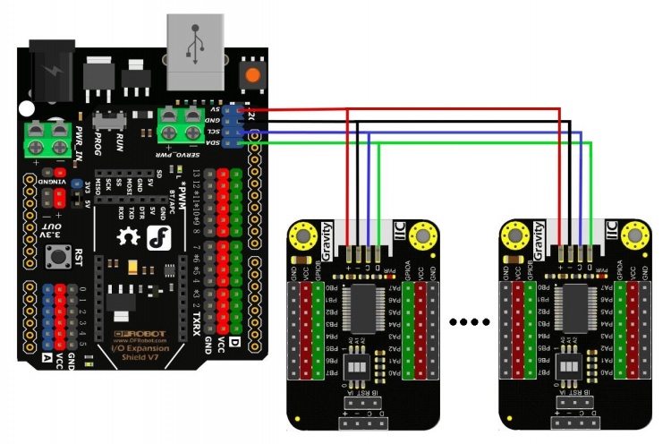
- 级联方式二

常见问题
还没有客户对此产品有任何问题,欢迎通过qq或者论坛联系我们!
更多问题及有趣的应用,可以 访问论坛 进行查阅或发帖。
